EP0764759A2 - Canal de tête pour stores à rouleau - Google Patents
Canal de tête pour stores à rouleau Download PDFInfo
- Publication number
- EP0764759A2 EP0764759A2 EP96114527A EP96114527A EP0764759A2 EP 0764759 A2 EP0764759 A2 EP 0764759A2 EP 96114527 A EP96114527 A EP 96114527A EP 96114527 A EP96114527 A EP 96114527A EP 0764759 A2 EP0764759 A2 EP 0764759A2
- Authority
- EP
- European Patent Office
- Prior art keywords
- flange
- headrail
- edge
- stem
- protruding
- Prior art date
- Legal status (The legal status is an assumption and is not a legal conclusion. Google has not performed a legal analysis and makes no representation as to the accuracy of the status listed.)
- Granted
Links
Images


Classifications
-
- E—FIXED CONSTRUCTIONS
- E06—DOORS, WINDOWS, SHUTTERS, OR ROLLER BLINDS IN GENERAL; LADDERS
- E06B—FIXED OR MOVABLE CLOSURES FOR OPENINGS IN BUILDINGS, VEHICLES, FENCES OR LIKE ENCLOSURES IN GENERAL, e.g. DOORS, WINDOWS, BLINDS, GATES
- E06B9/00—Screening or protective devices for wall or similar openings, with or without operating or securing mechanisms; Closures of similar construction
- E06B9/02—Shutters, movable grilles, or other safety closing devices, e.g. against burglary
- E06B9/08—Roll-type closures
- E06B9/11—Roller shutters
- E06B9/17—Parts or details of roller shutters, e.g. suspension devices, shutter boxes, wicket doors, ventilation openings
- E06B9/17007—Shutter boxes; Details or component parts thereof
-
- E—FIXED CONSTRUCTIONS
- E06—DOORS, WINDOWS, SHUTTERS, OR ROLLER BLINDS IN GENERAL; LADDERS
- E06B—FIXED OR MOVABLE CLOSURES FOR OPENINGS IN BUILDINGS, VEHICLES, FENCES OR LIKE ENCLOSURES IN GENERAL, e.g. DOORS, WINDOWS, BLINDS, GATES
- E06B9/00—Screening or protective devices for wall or similar openings, with or without operating or securing mechanisms; Closures of similar construction
- E06B9/24—Screens or other constructions affording protection against light, especially against sunshine; Similar screens for privacy or appearance; Slat blinds
- E06B9/40—Roller blinds
- E06B9/42—Parts or details of roller blinds, e.g. suspension devices, blind boxes
- E06B9/50—Bearings specially adapted therefor
Definitions
- This invention refers to a headrail for roller blinds.
- this invention refers to a headrail for roller blinds applied to windows or french windows, moved by hand or automatically.
- a traditional system for screening from the outside the windows of buildings is formed by blinds which unwrap from a roller located in a headrail and which slides, at the opposite ends, along guide profiles flush with the shoulders of the opening.
- the headrail located inside or outside the room in correspondence of the higher front of the opening, incorporates said roller as well as the manoeuvre devices of the same which allow the wrapping and unwrapping of the roller.
- Said manoeuvre devices are constituted in general by a pulley connected to a small belt, or by a winch or an electric motor.
- Said manoeuvre devices are housed near a side of the headrail, in a space circumscribed by the internal wall of said side and a flange connected to the same.
- the flange is provided in the middle with a through-seat for housing the roller, whose protruding pin engages with one of the aforementioned manoeuvre devices.
- connection of the flange with the side of the headrail, to create the housing seat for the manoeuvre device is generally realized by means of a plurality of screws, generally at least three, located near the peripheral portion of said flange suitably holed: the stem of the screws fits into corresponding holes obtained on the body of the headrail side.
- the screws located along the peripheral upper portion of the flange create discomfort during the installation of the headrail and cause a relevant increase in the overall assembly times.
- Object of this invention is to obviate the above drawbacks.
- object of this invention is to provide a headrail for roller blinds suitable to allow the quick and easy installation or removal of the flange which circumscribes, together with a side of the headrail, the housing space for the manoeuvre devices.
- a further object of the invention is to provide users with a headrail for roller blinds which, besides ensuring a high level of resistance and reliability in the time, can be realized easily and economically.
- a headrail for roller blinds comprising a container, having preferably a substantially parallelepipedal form, closed at each of the opposite ends by a side constituted by a plate having a forn complementary to that of the same headrail and provided with a lower internal edge, and at least a flange having a configuration complementary relatively to the profile of said edge, connected to the same to circumscribe a housing space for the manoeuvre devices of the roller blinds, wherein at least one of said sides, on its surface looking towards the inside of the container-body in correspondence of at least one of the vertices, has a connecting means partly protruding and the flange is correspondingly provided, on one or more vertices, with an arched profile chamfer.
- Said connecting means may be the stem of a screw, the stem of a pin having a head of a diameter greater than the diameter of the stem, obtained integrally with said side, or a protruding sector with a reverse-L profile.
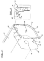
- the headreail for roller blinds of this invention comprises a container (10), from plastic material, wood or other suitable materials, constituted by a body of a substantially parallelepipedal form, closed at the opposite ends by a side (12) preferably from the same material as the container.
- the schematic views of Figs. 1, 3 and 5 show by way of example one only portion of the headrail and one only of the sides which close its ends. In particular, they show the side near which there is located and connected a flange (14) which circumscribes, with the internal wall of said side, the housing space for the manoeuvre devices of the roller blinds.
- Said flange (14) is formed by a plate, preferably from metal, having a limited thickness and a configuration complementary to that of the lower edge (16) obtained on side (12).
- Flange (14) is provided in the middle with a through hole (18) suitable to house an end of a roller (not represented) on which the roller blinds wrap.
- Side (12) furtherly comprises a cylindrical extension (20), obtained in the middle of its internal wall (12') and integral with said internal wall (12').
- the cylindrical extension (20) constitutes the anchoring means of the manoeuvre device, for instance a pulley, a winch or an electric motor, through which the roller blinds are moved and caused to wrap or unwrap from the roller.
- Side (12) is provided, on the internal wall (12') looking towards container (10), with a lower edge (16).
- Said edge (16) forms a perimetral frame of limited height, developed orthogonally, suitable to pressure-fit into the head of said container.
- the internal volume of container (10) is such as to house roller blinds for windows or french windows fully wrapped on the roller.
- roller blinds formed by a plurality of strips?from wood, plastic material, iron, aluminium or other materials, articulatable connected to one another with known means, is fitted, on the assembly into a tang (12), fitted, in its turn, into conventional slide guides or vertical sections?obtained along the shoulders of the opening, independently on whether the latter is a window or a french window.
- side (12) in correspondence of at least a vertix of edge (16), side (12) is provided, in correspondence of its surface looking towards the inside of the container, with a housing for a screw (24).
- the depth of said housing is advantageously smaller than the length of the stem of said screw, so that a part (26) of the stem and the head of both ends remain exposed after the full tightening, as represented, by way of example, in Fig. 1, and with more details in Fig. 2.
- FIG. 1 there are showns, according to a preferred non limitative embodiment, two aligned seats for as many screws (24), obtained along the internal upper horizontal portion of edge (16), in correspondence of the respective apices.
- the upper vertices of flange (14) have a chamfer (28), preferably with an arched profile to correspond to the configuration of a part of the stem of screw (24).
- the length of the exposed portion (26) of said stem, after the full tightening of screw (24) in the relevant seat, is equal to or slightly greater than the thickness of flange (14).
- the lower part of said flange (14), opposed to the one provided with seats for screws (24), in the position indicated by way of non limitative example in Fig. 1, has a through hole (30) for the insertion of a conventional screw (32), for instance of the self-theading type.
- the stem of said conventional screw (32) fits into a hole (34) obtained in correspondence of edge (16) of side (12).
- the depth of hole (34) is such as to house completely the stem of screw (12) which with its head counters flange (14).
- container (10) is positioned in the part above the opening and the opposing ends of the container are closed by a couple of identical sides (12).
- Flange (14) is easily and quickly located in the seat and stably connected to one of sides (12) according to a procedure specified hereunder.
- Flange (14) in positioned in such a way that the couple of aligned chamfers (28) are under the head of screws (24), already screwed up to the end of stroke in the respective seats obtained along edge (16) of side (12), with a hand action orientated upwards, as shown schematically in Figs. 1 and 2 by arrows "A".
- flange (14) is easily kept in a position substantially parallel to said side (12), in particular to its internal wall (12').
- the protruding portion of stem (26) of screws (24) has a length equal to or slightly greater than the thickness of flange (14) which, following such positioning, counters with chamfers (28) said stems.
- Figs. 3, 4 and 5, 6 for which the same reference numbers are used as in the preceding figures with regard to the common parts, represent as many alternative embodiments of the connecting system of the flange to the headrail side of this invention.
- FIGs. 3 and 4 show a headrail formed by a container (10) having a side (12) provided with a lower peripheral edge (16) and a flange (14) having a central hole (18) which is connected to the same side to circumscribe the housing of the manoeuvre device of the roller blinds.
- each of the upper vertices of edge (16) is provided on its surface looking towards the inside of container (10) with a prtruding pin (36), obtained integrally with side (12).
- the free end of pin (36) is provided with a cylindrical core or head (38) whose diameter is greater that the diameter of pin (36).
- Flange (14), identical to the one described above, is provided on the upper front with chamfers (28) obtained in correspondence of the vertices for the fitting under head (38) of pins (36).
- the protruding part of pin (36) comprised between edge (16) and head (38) has a length equal to or slightly greater than the thickness of flange (14).
- the stable connection of said flange (14) with side (12), after the approachement of chamfers (28) to the protruding part of each pin (36), is obtained with the same means as the preceding embodiment, i.e. with one only conventional screw (32) which, fitted in a hole obtained in a comfortable position in the lower part of flange (14), counters with its stem a hole (34) obtained along edge (16) of side (12).
- Figs. 5 and 6 show a further alternative embodiment of the connection system of the flange to the side of the heardrail of this invention.
- a protruding sector (40) having a reverse-L section.
- Said sector (40) forms an extension of said upper front of edge (16) from which it flush-develops and with respect to which it exdends longitudinally, preferably for a slightly lower height.
- the depth of the protruding sector (40) corresponds substantially to the thickness of flange (14).
- Flange (14) fits under the protruding sector (40), with its portion of the upper edge, as indicated by arrows "A" of Fig. 6.
- Said flange which in this case needs no chamfers in correspondence of the upper vertices, is afterwards locked against side (16), with the same means described in relation with the preceding embodiments, i.e. through one only screw (32).
- the connection of the flange with the side of the headrail to circumscribe the space housing the manoeuvre devices of the headrail is obtained, in all the embodiments, in a very quick and easy way. Also in a very quick and easy way it is possible to carry out the temporary removal of the flange in case of need of interventions for the repair or the replacement of the manoeuvre devices or their components.
- the screws or pins provided on the side of the headrail can be obtained in a number other that what has been described by way of example, or they can be located in other positions, with the related corresponding modification of the chamfers on the flange.
- the protruding sector with the reverse-L section can be developed along several portions of the side edge, not necessarily aligned to one another or on a same front.
Landscapes
- Engineering & Computer Science (AREA)
- Structural Engineering (AREA)
- Architecture (AREA)
- Civil Engineering (AREA)
- Blinds (AREA)
- Operating, Guiding And Securing Of Roll- Type Closing Members (AREA)
Applications Claiming Priority (2)
| Application Number | Priority Date | Filing Date | Title |
|---|---|---|---|
| IT95MI001971A IT1279906B1 (it) | 1995-09-25 | 1995-09-25 | Cassonetto perfezionato per avvolgibili |
| ITMI951971 | 1995-09-25 |
Publications (3)
| Publication Number | Publication Date |
|---|---|
| EP0764759A2 true EP0764759A2 (fr) | 1997-03-26 |
| EP0764759A3 EP0764759A3 (fr) | 1998-09-02 |
| EP0764759B1 EP0764759B1 (fr) | 2003-05-28 |
Family
ID=11372276
Family Applications (1)
| Application Number | Title | Priority Date | Filing Date |
|---|---|---|---|
| EP96114527A Expired - Lifetime EP0764759B1 (fr) | 1995-09-25 | 1996-09-11 | Canal de tête pour stores à rouleau |
Country Status (3)
| Country | Link |
|---|---|
| EP (1) | EP0764759B1 (fr) |
| DE (1) | DE69628385D1 (fr) |
| IT (1) | IT1279906B1 (fr) |
Cited By (5)
| Publication number | Priority date | Publication date | Assignee | Title |
|---|---|---|---|---|
| EP0939192A1 (fr) * | 1998-02-27 | 1999-09-01 | IMBAC S.p.A. | Rail supérieur pour volet roulant |
| FR2801631A1 (fr) | 1999-11-30 | 2001-06-01 | Simbac S P A | Dispositif de fixation d'un organe d'entrainement et mecanisme de manoeuvre d'une installation de fermeture ou de protection solaire comprenant un tel dispositif |
| FR2801632A1 (fr) | 1999-11-30 | 2001-06-01 | Simbac S P A | Dispositif de fixation d'un organe d'entrainement et mecanisme de manoeuvre d'une installation de fermeture ou de protection solaire comprenant un tel dispositif |
| ES2332754A1 (es) * | 2007-04-16 | 2010-02-11 | Antonio Carballo Vilarchao | Testero para cajas de persiana. |
| FR3080404A1 (fr) * | 2018-04-18 | 2019-10-25 | Profialis | Embout pour coffre de volet roulant et coffre associe |
Citations (3)
| Publication number | Priority date | Publication date | Assignee | Title |
|---|---|---|---|---|
| FR2403445A1 (fr) * | 1977-09-16 | 1979-04-13 | Crouzier | Caisson pour volet-roulant |
| DE9301459U1 (de) * | 1993-02-03 | 1993-03-25 | SKS Stakusit-Kunststoff GmbH & Co KG, 6108 Weiterstadt | Rolladenkasten |
| DE9302394U1 (de) * | 1993-02-19 | 1993-05-06 | Alulux Beckhoff KG, 4837 Verl | Rolladen |
-
1995
- 1995-09-25 IT IT95MI001971A patent/IT1279906B1/it active IP Right Grant
-
1996
- 1996-09-11 EP EP96114527A patent/EP0764759B1/fr not_active Expired - Lifetime
- 1996-09-11 DE DE69628385T patent/DE69628385D1/de not_active Expired - Lifetime
Patent Citations (3)
| Publication number | Priority date | Publication date | Assignee | Title |
|---|---|---|---|---|
| FR2403445A1 (fr) * | 1977-09-16 | 1979-04-13 | Crouzier | Caisson pour volet-roulant |
| DE9301459U1 (de) * | 1993-02-03 | 1993-03-25 | SKS Stakusit-Kunststoff GmbH & Co KG, 6108 Weiterstadt | Rolladenkasten |
| DE9302394U1 (de) * | 1993-02-19 | 1993-05-06 | Alulux Beckhoff KG, 4837 Verl | Rolladen |
Cited By (7)
| Publication number | Priority date | Publication date | Assignee | Title |
|---|---|---|---|---|
| EP0939192A1 (fr) * | 1998-02-27 | 1999-09-01 | IMBAC S.p.A. | Rail supérieur pour volet roulant |
| FR2801631A1 (fr) | 1999-11-30 | 2001-06-01 | Simbac S P A | Dispositif de fixation d'un organe d'entrainement et mecanisme de manoeuvre d'une installation de fermeture ou de protection solaire comprenant un tel dispositif |
| FR2801632A1 (fr) | 1999-11-30 | 2001-06-01 | Simbac S P A | Dispositif de fixation d'un organe d'entrainement et mecanisme de manoeuvre d'une installation de fermeture ou de protection solaire comprenant un tel dispositif |
| EP1106773A1 (fr) * | 1999-11-30 | 2001-06-13 | Simbac S.p.A | Dispositif de fixation d'un organe d'entraínement et mécanisme de manoeuvre d'une installation de fermeture ou de protection solaire comprenant un tel dispositif |
| EP1106774B1 (fr) * | 1999-11-30 | 2005-01-26 | Gaviota Simbac, S.L. | Dispositif de fixation d'un organe d'entraínement et mécanisme de manoeuvre d'une installation de fermeture ou de protection solaire comprenant un tel dispositif |
| ES2332754A1 (es) * | 2007-04-16 | 2010-02-11 | Antonio Carballo Vilarchao | Testero para cajas de persiana. |
| FR3080404A1 (fr) * | 2018-04-18 | 2019-10-25 | Profialis | Embout pour coffre de volet roulant et coffre associe |
Also Published As
| Publication number | Publication date |
|---|---|
| EP0764759B1 (fr) | 2003-05-28 |
| DE69628385D1 (de) | 2003-07-03 |
| EP0764759A3 (fr) | 1998-09-02 |
| ITMI951971A0 (fr) | 1995-09-25 |
| IT1279906B1 (it) | 1997-12-18 |
| ITMI951971A1 (it) | 1997-03-25 |
Similar Documents
| Publication | Publication Date | Title |
|---|---|---|
| AU2012202652B2 (en) | Shutter with field serviceable louvers | |
| EP1632635B1 (fr) | Dormant de porte | |
| EP2878757A2 (fr) | Assemblage sans cadre pour une grille de protection contre les insectes ou tissu en treillis similaire | |
| DE69206201T2 (de) | Badewannentür mit aufblasbarer Dichtung. | |
| EP0764759A2 (fr) | Canal de tête pour stores à rouleau | |
| JPH0343589A (ja) | コード釣合装置 | |
| DE102005001624A1 (de) | Kombinierbare Steckzarge | |
| DE102005001622A1 (de) | Zargenvorrichtung für Öffnungen in Wänden | |
| DE4314101A1 (de) | Armatur mit Bajonettverschluß | |
| EP1529179B1 (fr) | Plafonnier comprenant un boitier allonge | |
| EP1587194A2 (fr) | Elément d'installation pour loger lignes d'alimentation | |
| DE3643075A1 (de) | Vorhangbeleuchtung | |
| DE102008040610A1 (de) | Deckel zum Abdecken eines Lagerzapfens eines Lagerwinkels sowie damit ausgerüstetes Haushaltsgerät | |
| DE69402823T2 (de) | Tragevorrichtung für Rolladenantrieb | |
| KR101103307B1 (ko) | 양문형 출입문용 고정장치 | |
| DE4321466C2 (de) | Zarge für ein Fenster | |
| JP4198250B2 (ja) | 配線器具用化粧プレート | |
| DE3037703C2 (de) | Lemellenjalousie mit einem raffbaren Lamellenbehang mit verschwenkbaren Lamellen | |
| DE29716263U1 (de) | Bausatz für Türzargen mit integrierter Leuchte | |
| DE202017105448U1 (de) | Wandhalter und Befestigungsset | |
| DE4128355C1 (en) | Electronic equipment housing e.g. TV, radio cabinet, allowing access for servicing - has frame for walls using plug flaps fitting grooves and held in place by spring-loaded fasteners releasable by operating elements | |
| KR100472428B1 (ko) | 엘리베이터 고장에 의한 수동으로 문 열리는 비치(비상)용 래크 탈출기 | |
| DE29701381U1 (de) | Installationsgeräte-Einbaueinheit für eine Aufflurelektroinstallation | |
| DE8712539U1 (de) | Sockel für Fahrtreppen und Fahrsteige | |
| JPH0738637Y2 (ja) | 通風建具における嵌込みユニットの固定装置 |
Legal Events
| Date | Code | Title | Description |
|---|---|---|---|
| PUAI | Public reference made under article 153(3) epc to a published international application that has entered the european phase |
Free format text: ORIGINAL CODE: 0009012 |
|
| AK | Designated contracting states |
Kind code of ref document: A2 Designated state(s): DE ES FR |
|
| PUAL | Search report despatched |
Free format text: ORIGINAL CODE: 0009013 |
|
| RHK1 | Main classification (correction) |
Ipc: E06B 9/17 |
|
| AK | Designated contracting states |
Kind code of ref document: A3 Designated state(s): DE ES FR |
|
| 17P | Request for examination filed |
Effective date: 19981012 |
|
| 17Q | First examination report despatched |
Effective date: 20020326 |
|
| GRAH | Despatch of communication of intention to grant a patent |
Free format text: ORIGINAL CODE: EPIDOS IGRA |
|
| GRAH | Despatch of communication of intention to grant a patent |
Free format text: ORIGINAL CODE: EPIDOS IGRA |
|
| GRAA | (expected) grant |
Free format text: ORIGINAL CODE: 0009210 |
|
| AK | Designated contracting states |
Designated state(s): DE ES FR |
|
| PG25 | Lapsed in a contracting state [announced via postgrant information from national office to epo] |
Ref country code: FR Free format text: LAPSE BECAUSE OF FAILURE TO SUBMIT A TRANSLATION OF THE DESCRIPTION OR TO PAY THE FEE WITHIN THE PRESCRIBED TIME-LIMIT Effective date: 20030528 |
|
| REF | Corresponds to: |
Ref document number: 69628385 Country of ref document: DE Date of ref document: 20030703 Kind code of ref document: P |
|
| PG25 | Lapsed in a contracting state [announced via postgrant information from national office to epo] |
Ref country code: DE Free format text: LAPSE BECAUSE OF FAILURE TO SUBMIT A TRANSLATION OF THE DESCRIPTION OR TO PAY THE FEE WITHIN THE PRESCRIBED TIME-LIMIT Effective date: 20030829 |
|
| PG25 | Lapsed in a contracting state [announced via postgrant information from national office to epo] |
Ref country code: ES Free format text: LAPSE BECAUSE OF FAILURE TO SUBMIT A TRANSLATION OF THE DESCRIPTION OR TO PAY THE FEE WITHIN THE PRESCRIBED TIME-LIMIT Effective date: 20030908 |
|
| PLBE | No opposition filed within time limit |
Free format text: ORIGINAL CODE: 0009261 |
|
| STAA | Information on the status of an ep patent application or granted ep patent |
Free format text: STATUS: NO OPPOSITION FILED WITHIN TIME LIMIT |
|
| 26N | No opposition filed |
Effective date: 20040302 |
|
| EN | Fr: translation not filed |