EP0764584A2 - Dispositif d'emballage - Google Patents
Dispositif d'emballage Download PDFInfo
- Publication number
- EP0764584A2 EP0764584A2 EP96109481A EP96109481A EP0764584A2 EP 0764584 A2 EP0764584 A2 EP 0764584A2 EP 96109481 A EP96109481 A EP 96109481A EP 96109481 A EP96109481 A EP 96109481A EP 0764584 A2 EP0764584 A2 EP 0764584A2
- Authority
- EP
- European Patent Office
- Prior art keywords
- linear drive
- product
- movable part
- stamp
- conveyor belt
- Prior art date
- Legal status (The legal status is an assumption and is not a legal conclusion. Google has not performed a legal analysis and makes no representation as to the accuracy of the status listed.)
- Ceased
Links
Images


Classifications
-
- B—PERFORMING OPERATIONS; TRANSPORTING
- B65—CONVEYING; PACKING; STORING; HANDLING THIN OR FILAMENTARY MATERIAL
- B65B—MACHINES, APPARATUS OR DEVICES FOR, OR METHODS OF, PACKAGING ARTICLES OR MATERIALS; UNPACKING
- B65B65/00—Details peculiar to packaging machines and not otherwise provided for; Arrangements of such details
- B65B65/02—Driving gear
-
- B—PERFORMING OPERATIONS; TRANSPORTING
- B29—WORKING OF PLASTICS; WORKING OF SUBSTANCES IN A PLASTIC STATE IN GENERAL
- B29C—SHAPING OR JOINING OF PLASTICS; SHAPING OF MATERIAL IN A PLASTIC STATE, NOT OTHERWISE PROVIDED FOR; AFTER-TREATMENT OF THE SHAPED PRODUCTS, e.g. REPAIRING
- B29C66/00—General aspects of processes or apparatus for joining preformed parts
- B29C66/01—General aspects dealing with the joint area or with the area to be joined
- B29C66/05—Particular design of joint configurations
- B29C66/10—Particular design of joint configurations particular design of the joint cross-sections
- B29C66/11—Joint cross-sections comprising a single joint-segment, i.e. one of the parts to be joined comprising a single joint-segment in the joint cross-section
- B29C66/112—Single lapped joints
- B29C66/1122—Single lap to lap joints, i.e. overlap joints
-
- B—PERFORMING OPERATIONS; TRANSPORTING
- B29—WORKING OF PLASTICS; WORKING OF SUBSTANCES IN A PLASTIC STATE IN GENERAL
- B29C—SHAPING OR JOINING OF PLASTICS; SHAPING OF MATERIAL IN A PLASTIC STATE, NOT OTHERWISE PROVIDED FOR; AFTER-TREATMENT OF THE SHAPED PRODUCTS, e.g. REPAIRING
- B29C66/00—General aspects of processes or apparatus for joining preformed parts
- B29C66/40—General aspects of joining substantially flat articles, e.g. plates, sheets or web-like materials; Making flat seams in tubular or hollow articles; Joining single elements to substantially flat surfaces
- B29C66/41—Joining substantially flat articles ; Making flat seams in tubular or hollow articles
- B29C66/43—Joining a relatively small portion of the surface of said articles
- B29C66/431—Joining the articles to themselves
- B29C66/4312—Joining the articles to themselves for making flat seams in tubular or hollow articles, e.g. transversal seams
- B29C66/43121—Closing the ends of tubular or hollow single articles, e.g. closing the ends of bags
-
- B—PERFORMING OPERATIONS; TRANSPORTING
- B29—WORKING OF PLASTICS; WORKING OF SUBSTANCES IN A PLASTIC STATE IN GENERAL
- B29C—SHAPING OR JOINING OF PLASTICS; SHAPING OF MATERIAL IN A PLASTIC STATE, NOT OTHERWISE PROVIDED FOR; AFTER-TREATMENT OF THE SHAPED PRODUCTS, e.g. REPAIRING
- B29C66/00—General aspects of processes or apparatus for joining preformed parts
- B29C66/40—General aspects of joining substantially flat articles, e.g. plates, sheets or web-like materials; Making flat seams in tubular or hollow articles; Joining single elements to substantially flat surfaces
- B29C66/41—Joining substantially flat articles ; Making flat seams in tubular or hollow articles
- B29C66/43—Joining a relatively small portion of the surface of said articles
- B29C66/432—Joining a relatively small portion of the surface of said articles for making tubular articles or closed loops, e.g. by joining several sheets ; for making hollow articles or hollow preforms
- B29C66/4322—Joining a relatively small portion of the surface of said articles for making tubular articles or closed loops, e.g. by joining several sheets ; for making hollow articles or hollow preforms by joining a single sheet to itself
-
- B—PERFORMING OPERATIONS; TRANSPORTING
- B29—WORKING OF PLASTICS; WORKING OF SUBSTANCES IN A PLASTIC STATE IN GENERAL
- B29C—SHAPING OR JOINING OF PLASTICS; SHAPING OF MATERIAL IN A PLASTIC STATE, NOT OTHERWISE PROVIDED FOR; AFTER-TREATMENT OF THE SHAPED PRODUCTS, e.g. REPAIRING
- B29C66/00—General aspects of processes or apparatus for joining preformed parts
- B29C66/40—General aspects of joining substantially flat articles, e.g. plates, sheets or web-like materials; Making flat seams in tubular or hollow articles; Joining single elements to substantially flat surfaces
- B29C66/49—Internally supporting the, e.g. tubular, article during joining
-
- B—PERFORMING OPERATIONS; TRANSPORTING
- B29—WORKING OF PLASTICS; WORKING OF SUBSTANCES IN A PLASTIC STATE IN GENERAL
- B29C—SHAPING OR JOINING OF PLASTICS; SHAPING OF MATERIAL IN A PLASTIC STATE, NOT OTHERWISE PROVIDED FOR; AFTER-TREATMENT OF THE SHAPED PRODUCTS, e.g. REPAIRING
- B29C66/00—General aspects of processes or apparatus for joining preformed parts
- B29C66/80—General aspects of machine operations or constructions and parts thereof
- B29C66/84—Specific machine types or machines suitable for specific applications
- B29C66/849—Packaging machines
- B29C66/8491—Packaging machines welding through a filled container, e.g. tube or bag
-
- B—PERFORMING OPERATIONS; TRANSPORTING
- B29—WORKING OF PLASTICS; WORKING OF SUBSTANCES IN A PLASTIC STATE IN GENERAL
- B29C—SHAPING OR JOINING OF PLASTICS; SHAPING OF MATERIAL IN A PLASTIC STATE, NOT OTHERWISE PROVIDED FOR; AFTER-TREATMENT OF THE SHAPED PRODUCTS, e.g. REPAIRING
- B29C65/00—Joining or sealing of preformed parts, e.g. welding of plastics materials; Apparatus therefor
- B29C65/02—Joining or sealing of preformed parts, e.g. welding of plastics materials; Apparatus therefor by heating, with or without pressure
- B29C65/18—Joining or sealing of preformed parts, e.g. welding of plastics materials; Apparatus therefor by heating, with or without pressure using heated tools
-
- B—PERFORMING OPERATIONS; TRANSPORTING
- B29—WORKING OF PLASTICS; WORKING OF SUBSTANCES IN A PLASTIC STATE IN GENERAL
- B29C—SHAPING OR JOINING OF PLASTICS; SHAPING OF MATERIAL IN A PLASTIC STATE, NOT OTHERWISE PROVIDED FOR; AFTER-TREATMENT OF THE SHAPED PRODUCTS, e.g. REPAIRING
- B29C65/00—Joining or sealing of preformed parts, e.g. welding of plastics materials; Apparatus therefor
- B29C65/74—Joining or sealing of preformed parts, e.g. welding of plastics materials; Apparatus therefor by welding and severing, or by joining and severing, the severing being performed in the area to be joined, next to the area to be joined, in the joint area or next to the joint area
- B29C65/745—Joining or sealing of preformed parts, e.g. welding of plastics materials; Apparatus therefor by welding and severing, or by joining and severing, the severing being performed in the area to be joined, next to the area to be joined, in the joint area or next to the joint area using a single unit having both a severing tool and a welding tool
- B29C65/7451—Joining or sealing of preformed parts, e.g. welding of plastics materials; Apparatus therefor by welding and severing, or by joining and severing, the severing being performed in the area to be joined, next to the area to be joined, in the joint area or next to the joint area using a single unit having both a severing tool and a welding tool the severing tool and the welding tool being movable with respect to one-another
-
- B—PERFORMING OPERATIONS; TRANSPORTING
- B29—WORKING OF PLASTICS; WORKING OF SUBSTANCES IN A PLASTIC STATE IN GENERAL
- B29C—SHAPING OR JOINING OF PLASTICS; SHAPING OF MATERIAL IN A PLASTIC STATE, NOT OTHERWISE PROVIDED FOR; AFTER-TREATMENT OF THE SHAPED PRODUCTS, e.g. REPAIRING
- B29C65/00—Joining or sealing of preformed parts, e.g. welding of plastics materials; Apparatus therefor
- B29C65/78—Means for handling the parts to be joined, e.g. for making containers or hollow articles, e.g. means for handling sheets, plates, web-like materials, tubular articles, hollow articles or elements to be joined therewith; Means for discharging the joined articles from the joining apparatus
- B29C65/7897—Means for discharging the joined articles from the joining apparatus
-
- B—PERFORMING OPERATIONS; TRANSPORTING
- B29—WORKING OF PLASTICS; WORKING OF SUBSTANCES IN A PLASTIC STATE IN GENERAL
- B29C—SHAPING OR JOINING OF PLASTICS; SHAPING OF MATERIAL IN A PLASTIC STATE, NOT OTHERWISE PROVIDED FOR; AFTER-TREATMENT OF THE SHAPED PRODUCTS, e.g. REPAIRING
- B29C66/00—General aspects of processes or apparatus for joining preformed parts
- B29C66/80—General aspects of machine operations or constructions and parts thereof
- B29C66/81—General aspects of the pressing elements, i.e. the elements applying pressure on the parts to be joined in the area to be joined, e.g. the welding jaws or clamps
- B29C66/814—General aspects of the pressing elements, i.e. the elements applying pressure on the parts to be joined in the area to be joined, e.g. the welding jaws or clamps characterised by the design of the pressing elements, e.g. of the welding jaws or clamps
- B29C66/8141—General aspects of the pressing elements, i.e. the elements applying pressure on the parts to be joined in the area to be joined, e.g. the welding jaws or clamps characterised by the design of the pressing elements, e.g. of the welding jaws or clamps characterised by the surface geometry of the part of the pressing elements, e.g. welding jaws or clamps, coming into contact with the parts to be joined
- B29C66/81427—General aspects of the pressing elements, i.e. the elements applying pressure on the parts to be joined in the area to be joined, e.g. the welding jaws or clamps characterised by the design of the pressing elements, e.g. of the welding jaws or clamps characterised by the surface geometry of the part of the pressing elements, e.g. welding jaws or clamps, coming into contact with the parts to be joined comprising a single ridge, e.g. for making a weakening line; comprising a single tooth
-
- B—PERFORMING OPERATIONS; TRANSPORTING
- B29—WORKING OF PLASTICS; WORKING OF SUBSTANCES IN A PLASTIC STATE IN GENERAL
- B29C—SHAPING OR JOINING OF PLASTICS; SHAPING OF MATERIAL IN A PLASTIC STATE, NOT OTHERWISE PROVIDED FOR; AFTER-TREATMENT OF THE SHAPED PRODUCTS, e.g. REPAIRING
- B29C66/00—General aspects of processes or apparatus for joining preformed parts
- B29C66/80—General aspects of machine operations or constructions and parts thereof
- B29C66/81—General aspects of the pressing elements, i.e. the elements applying pressure on the parts to be joined in the area to be joined, e.g. the welding jaws or clamps
- B29C66/814—General aspects of the pressing elements, i.e. the elements applying pressure on the parts to be joined in the area to be joined, e.g. the welding jaws or clamps characterised by the design of the pressing elements, e.g. of the welding jaws or clamps
- B29C66/8141—General aspects of the pressing elements, i.e. the elements applying pressure on the parts to be joined in the area to be joined, e.g. the welding jaws or clamps characterised by the design of the pressing elements, e.g. of the welding jaws or clamps characterised by the surface geometry of the part of the pressing elements, e.g. welding jaws or clamps, coming into contact with the parts to be joined
- B29C66/81431—General aspects of the pressing elements, i.e. the elements applying pressure on the parts to be joined in the area to be joined, e.g. the welding jaws or clamps characterised by the design of the pressing elements, e.g. of the welding jaws or clamps characterised by the surface geometry of the part of the pressing elements, e.g. welding jaws or clamps, coming into contact with the parts to be joined comprising a single cavity, e.g. a groove
-
- B—PERFORMING OPERATIONS; TRANSPORTING
- B29—WORKING OF PLASTICS; WORKING OF SUBSTANCES IN A PLASTIC STATE IN GENERAL
- B29C—SHAPING OR JOINING OF PLASTICS; SHAPING OF MATERIAL IN A PLASTIC STATE, NOT OTHERWISE PROVIDED FOR; AFTER-TREATMENT OF THE SHAPED PRODUCTS, e.g. REPAIRING
- B29C66/00—General aspects of processes or apparatus for joining preformed parts
- B29C66/80—General aspects of machine operations or constructions and parts thereof
- B29C66/81—General aspects of the pressing elements, i.e. the elements applying pressure on the parts to be joined in the area to be joined, e.g. the welding jaws or clamps
- B29C66/814—General aspects of the pressing elements, i.e. the elements applying pressure on the parts to be joined in the area to be joined, e.g. the welding jaws or clamps characterised by the design of the pressing elements, e.g. of the welding jaws or clamps
- B29C66/8141—General aspects of the pressing elements, i.e. the elements applying pressure on the parts to be joined in the area to be joined, e.g. the welding jaws or clamps characterised by the design of the pressing elements, e.g. of the welding jaws or clamps characterised by the surface geometry of the part of the pressing elements, e.g. welding jaws or clamps, coming into contact with the parts to be joined
- B29C66/81433—General aspects of the pressing elements, i.e. the elements applying pressure on the parts to be joined in the area to be joined, e.g. the welding jaws or clamps characterised by the design of the pressing elements, e.g. of the welding jaws or clamps characterised by the surface geometry of the part of the pressing elements, e.g. welding jaws or clamps, coming into contact with the parts to be joined being toothed, i.e. comprising several teeth or pins, or being patterned
-
- B—PERFORMING OPERATIONS; TRANSPORTING
- B29—WORKING OF PLASTICS; WORKING OF SUBSTANCES IN A PLASTIC STATE IN GENERAL
- B29C—SHAPING OR JOINING OF PLASTICS; SHAPING OF MATERIAL IN A PLASTIC STATE, NOT OTHERWISE PROVIDED FOR; AFTER-TREATMENT OF THE SHAPED PRODUCTS, e.g. REPAIRING
- B29C66/00—General aspects of processes or apparatus for joining preformed parts
- B29C66/80—General aspects of machine operations or constructions and parts thereof
- B29C66/83—General aspects of machine operations or constructions and parts thereof characterised by the movement of the joining or pressing tools
- B29C66/834—General aspects of machine operations or constructions and parts thereof characterised by the movement of the joining or pressing tools moving with the parts to be joined
- B29C66/8351—Jaws mounted on rollers, cylinders, drums, bands, belts or chains; Flying jaws
- B29C66/83511—Jaws mounted on rollers, cylinders, drums, bands, belts or chains; Flying jaws jaws mounted on rollers, cylinders or drums
- B29C66/83513—Jaws mounted on rollers, cylinders, drums, bands, belts or chains; Flying jaws jaws mounted on rollers, cylinders or drums cooperating jaws mounted on rollers, cylinders or drums and moving in a closed path
-
- B—PERFORMING OPERATIONS; TRANSPORTING
- B29—WORKING OF PLASTICS; WORKING OF SUBSTANCES IN A PLASTIC STATE IN GENERAL
- B29C—SHAPING OR JOINING OF PLASTICS; SHAPING OF MATERIAL IN A PLASTIC STATE, NOT OTHERWISE PROVIDED FOR; AFTER-TREATMENT OF THE SHAPED PRODUCTS, e.g. REPAIRING
- B29C66/00—General aspects of processes or apparatus for joining preformed parts
- B29C66/80—General aspects of machine operations or constructions and parts thereof
- B29C66/83—General aspects of machine operations or constructions and parts thereof characterised by the movement of the joining or pressing tools
- B29C66/834—General aspects of machine operations or constructions and parts thereof characterised by the movement of the joining or pressing tools moving with the parts to be joined
- B29C66/8351—Jaws mounted on rollers, cylinders, drums, bands, belts or chains; Flying jaws
- B29C66/83541—Jaws mounted on rollers, cylinders, drums, bands, belts or chains; Flying jaws flying jaws, e.g. jaws mounted on crank mechanisms or following a hand over hand movement
- B29C66/83543—Jaws mounted on rollers, cylinders, drums, bands, belts or chains; Flying jaws flying jaws, e.g. jaws mounted on crank mechanisms or following a hand over hand movement cooperating flying jaws
-
- B—PERFORMING OPERATIONS; TRANSPORTING
- B65—CONVEYING; PACKING; STORING; HANDLING THIN OR FILAMENTARY MATERIAL
- B65B—MACHINES, APPARATUS OR DEVICES FOR, OR METHODS OF, PACKAGING ARTICLES OR MATERIALS; UNPACKING
- B65B9/00—Enclosing successive articles, or quantities of material, e.g. liquids or semiliquids, in flat, folded, or tubular webs of flexible sheet material; Subdividing filled flexible tubes to form packages
- B65B9/10—Enclosing successive articles, or quantities of material, in preformed tubular webs, or in webs formed into tubes around filling nozzles, e.g. extruded tubular webs
- B65B9/20—Enclosing successive articles, or quantities of material, in preformed tubular webs, or in webs formed into tubes around filling nozzles, e.g. extruded tubular webs the webs being formed into tubes in situ around the filling nozzles
Definitions
- the invention relates to a device for packaging with a device for acting against the product to be packaged, the packaging or a part of the packaging.
- Devices for packaging which act against the product to be packaged, on which a product to be packaged is cyclically accelerated by means of an electric motor-driven conveyor belt and is fed to a packaging machine in this way.
- vertical tubular bag machines are known as devices in which the product to be packaged is accelerated by being exposed to free fall in a filling tube.
- the conveyor belt itself or parts of the conveyor belt serve as a device for guiding the moving product and the filling tube is used in the vertical tubular bag machine.
- a flowable product e.g. Powder or granules are fed from a storage vessel to the volume metering and are generally dispensed in portions from the volume metering device on the bottom side.
- the delivery can e.g. into the filling tube of a vertical tubular bag machine. Then the product is packed in portions in tubular bags.
- Packaging devices which act against the packaging or a part thereof are also well known. On tubular bag machines, the bag seams are welded using sealing devices. For cartoners, the flaps of folding boxes are folded over and glued together. Electric motors are used to drive the closing mechanism of a closing device.
- Devices with separation devices for packaging material are also known. These are, for example, electromotively driven lancing knives or cutting devices for cutting through a flat film web, for separating a finished bag from a film web or for punching out a hanging hole from the wrapping material of a bag. Such devices are used on tubular bag machines.
- the device for taking away the packaging material is a film take-off, a carton blank, a cup belt, a suction gripper or a label dispenser. Electric motors are used as a device for moving the packaging material taken along.
- the known devices have the disadvantage that they are too slow for the acceleration of the product to be packaged, the packaging of part of the packaging, or for the treatment of packaging or product for use in high-performance packaging machines.
- many of the known mechanical connections would be unsuitable for the transmission of extremely large accelerations, since they have relatively large moments of inertia.
- high speeds resulting from large accelerations would not be sufficiently decelerable with the known electric motors.
- the invention is based on the object of designing a device of the type described in the introduction such that extremely high acceleration values on the one hand and correspondingly high deceleration values of the device can be achieved on the other hand.
- the mechanical connections are to be adapted to the transmission of the high acceleration and deceleration forces.
- an electromagnetic linear drive (linear motor) is provided with a movable part and a part driving the movable part, and the movable part is provided with the device for acting against the product to be packaged Packaging or part of the packaging connected.
- the device according to the invention has the advantage that acceleration and deceleration values up to twenty times the acceleration due to gravity can be achieved.
- This acceleration is experienced by the movable part on an electromagnetic linear drive compared to a driving part of the linear drive or a driven part relative to the linear drive.
- the moving part moves the device and this in turn acts on the product to be packaged or the packaging indirectly or through direct contact with the product.
- the device is accelerated by the linear drive and the device accelerates the product, the packaging or a tool which acts on the product or the packaging.
- the linear drive is positioned precisely for the purpose of acceleration and reset again. When the device comes into direct contact with the product, there is no longer any inert mechanical connection, and the movement is therefore carried out without a large moment of inertia.
- High-performance packaging machines can be realized with the device according to the invention.
- a stamp (claim 2)
- maximum product acceleration can be achieved since the mass to be accelerated is minimized.
- the stamp acts indirectly on the product via the device for guiding the moving product (claim 3)
- a set of products which are located on or on the device can experience the acceleration.
- a device can be a conveyor belt.
- the conveyor belt can e.g. Transport a series of open empty bags to a filling station and on to a bag closing station. The entire clocked transport process can take place by means of an electromagnetic linear drive.
- a combination of two accelerations running perpendicular to each other is achieved with a combination of two electromagnetic linear drives.
- the driving part of one linear drive is connected to the movable part of the other linear drive, and the movable parts of the linear drives are shifted in directions that are in a plane and perpendicular to each other.
- the other linear drive can completely shifted in parallel by this amount of deflection.
- the entirety of the two linear drives can thus be moved along a stamp along a path that is otherwise limited by the maximum displacement paths of the linear drives, for example along a parallelogram, a circular path or an elliptical path.
- the device for guiding the moving product is the filling tube of a vertical tubular bag machine, then the free fall in the filling tube, the filling portions or bag inserts can be further accelerated in their downward movement in addition to the acceleration due to gravity.
- Cardboard blanks which are inserted as an insert into bags in order to give the bags an improved stability or stability can be introduced through the filling tube of a tubular bag machine into the bags to be produced by means of a stamp if the stamp can be moved axially from above into the filling tube , and a placement station for individual cardboard blanks is provided directly above the filling tube.
- the cardboard blanks can be pre-folded and folded over by the resistance of the upper filling tube end.
- the stamp it is possible for the stamp to be provided on a device for free-fall dispensing, and for the stamp to act downward in the space through which the product falls.
- This facility can e.g. be a flap that releases a measured portion of the product downwards.
- the stamp then hurries e.g. the falling portion of the product and accelerate it further down a path.
- the stamp can, however, also act from above in a metering device and push the product portion provided in the metering device out of it and, with the metering device already open, bring the product portion further to the lower end of the filling tube. If the stamp cross section is precisely and tightly matched to the clear cross section of the filling tube, product swarms can also be completely captured by the stamp.
- the filling tube is not a filling tube of a conventional vertical tubular bag machine, since in such a filling tube the hose is guided on the filling tube.
- the filling tube into which the punch is radial can be introduced is a filling tube for filling prefabricated containers.
- One linear drive is aligned parallel to the fill tube, and the other linear drive is aligned radially to the fill tube.
- the fill tube has an axially extending slot. At the ends of the slot there is a tangential recess in the filling tube.
- the stamp is inserted through the upper recess into the filling tube, then accelerates the product downwards, a rod, with which the stamp is connected to the movable part of the linear drive, is moved downwards in the slot, and finally the stamp is moved through the lower recess removed from the filling pipe.
- a rod with which the stamp is connected to the movable part of the linear drive, is moved downwards in the slot, and finally the stamp is moved through the lower recess removed from the filling pipe.
- the stamp is provided in the horizontal direction transversely to the conveyor belt, and the stamp acts in the direction of a vertically oriented boundary of the conveyor belt, e.g.
- the conveyor belt is at a standstill, one loot can be pushed into a box if the boxes touch the boundary and the bags are each in front of an opening in a box.
- Such a bag can also be inserted with a continuously moving conveyor belt. Since the bag insert runs extremely quickly, a stationary driving part of the linear drive is possible.
- the linear drive inserting the bags can be attached to a second linear drive, the second linear drive always displacing and resetting the first linear drive parallel to the transport device and in the transport direction.
- a bag is always inserted during a displacement of the first linear drive in the transport direction. After a reset, the next bag is inserted.
- the stamp can also push defective products off a conveyor belt.
- the defective products are recognized by a sensor.
- the measured values of the sensor are then used to control the linear drive, which deflects the stamp.
- a stamp which can be displaced in the horizontal direction can be moved into a product drop distance, and if a sensor for detecting defective product is provided on the product drop distance, then defective products can be recognized in free fall and thrown out of the product stream.
- the stamp can also be used to insert brochures or other stable items in folding boxes.
- the stamp is designed as the head of a prospectus shooter and can be moved transversely to the conveyor belt and against a prospectus shelf.
- closing processes can be implemented extremely quickly.
- the closing mechanism is a cross jaw closing device with two mutually movable transverse jaws of a vertical tubular bag machine (claim 7), then an extremely fast jaw movement can be realized for the top and bottom seam production.
- the exact displacement distance is also advantageous because on the one hand the cross jaws can be placed precisely in a closed position, on the other hand the cross jaws can still perform other functions by means of devices attached to them.
- the two cross jaws can be moved against each other by means of a simple locking mechanism if one cross jaw is connected to the movable part and the other cross jaw is connected to the driving part of the electromagnetic linear drive.
- the locking mechanism consists only of the mechanical connections between the linear drive and the cross jaws.
- a transverse welding device can be implemented in such a way that the movable part of the electromagnetic linear drive is connected to a piston sliding in the pressure transmission device, that each transverse jaw is connected to a piston and that the pistons protrude into the pressure transmission device.
- the medium inside the pressure transmission device transmits the pressure exerted by the linear drive via the pistons to the cross jaws. If the pressure transmission device contains a liquid, so the pressure transfer is undamped, if it contains a gas, the pressure transfer is damped.
- the side gusset pliers can be driven by means of a common linear drive or by means of separate linear drives.
- the side gusset punches insert the side gussets into the bag material before cross-sealing.
- the movable part of the electromagnetic linear drive is configured as a bag flag winder and a cup belt is provided for feeding bags with an end-sided flag to the bag flag winder.
- the stability of the bags during the flag laying is ensured by the design of the conveyor belt as a cup belt.
- a bottom seam sealing on tubular bags is possible in an embodiment of a closing device according to claim 10.
- the movable part of the electromagnetic linear drive is connected to a stamp
- the stamp can be moved vertically in a filling tube of a vertical tubular bag machine, and transverse jaws are provided below the filling tube, which form a mechanical resistance against the stamp.
- the stamp presses the welded hose end against the cross jaws, so that the bottom seam is sealed. Due to the extremely high speed of feeding and removing the stamp through the filling tube, the filling process is hardly influenced.
- the flaps of open folding boxes can be bent and closed in the glued state and thus glued if the movable part of the electromagnetic linear drive is connected to a flap closer and a conveyor belt is provided for feeding open folding boxes to the flap closer (claim 11).
- a cover strap closer or a side strap closer is reached.
- Folded boxes lying flat are particularly suitable for a cover flap closer acting vertically against the conveyor belt and a side gusset closer acting parallel to the surface of the conveyor belt.
- blanks for covers of boxes, but also other packaging parts can be moved for the purpose of closing them if the movable part of an electromagnetic linear drive is connected to a gripper.
- the movement of a gripper, a cross sealing jaw or another component is freely determinable if, according to claim 12, the movable part of an electromagnetic linear drive is connected to the driving part of a further linear drive, and the movable parts of the linear drives are displaceable in directions that are in one plane and run perpendicular to each other.
- This combination of two linear drives allows accelerations or movements that run perpendicular to each other to be added together.
- the other linear drive is completely shifted in parallel by this deflection amount.
- the entirety of the two linear drives can thus be moved along a closing mechanism along a path which is limited by the maximum displacement paths of the linear drives and is otherwise arbitrary.
- a cross jaw e.g. a movement along a parallelogram, circular or elliptical path of interest.
- a closing device according to claim 13.
- at least one glue application nozzle is provided along a conveyor belt
- a capping station is provided downstream of the glue application nozzle in the transport direction
- at least one vertically movable flap turner driven by an electromagnetic linear drive, is provided on the capping station.
- This closing device closes open boxes at the top with a lid.
- the lid is formed from a blank on the box.
- the lid is glued to the box.
- a separator must be provided as a device (claim 14) that the separator can be accelerated up to twenty times the acceleration due to gravity. This acceleration is experienced by the movable part on an electromagnetic linear drive compared to a driving part of the linear drive or a driven part relative to the linear drive.
- the moving part moves the separator.
- the separating device and its mechanics can be simply designed. The separating device is moved precisely and in time. The packaging material is cut so quickly that it can also be done with moving packaging material. High-performance packaging machines can be realized with the separating device according to the invention.
- the separating device is a web cutter movable tangentially to a film web, and if the web cutter is guided along a straight guide (claim 15), then a film web can be cut in a straight line transverse to its transport device. Since the cutting takes place extremely quickly, it can also be done when the film web is moving. As a result of the high cutting speed, the section takes place virtually perpendicular to the transport device of the film web, even when the film web is moving. Rapid web separation and the attachment of a new film web to the separation point of the old film web is particularly important on the film feed of a tubular bag machine.
- a kink edge is provided parallel to the guide for kinking the film web, and if a blade of the web cutter can be moved along the kink edge, the film web is stretched somewhat at the kink edge, and the film web can thereby be cut more securely in a straight line.
- the separating device is a piercing knife and the piercing knife is displaceable in a recess in a transverse jaw of a tubular bag machine.
- the separating device can be designed as a punch (claim 17) in a cross jaw of a tubular bag machine.
- a head seam and a welding surface producing a bottom seam are provided on the cross jaw.
- the punch is perpendicular to the welding surface for the head seam and normal through this using a Leadership led.
- the guide can be a recess through which a punched part configured as a bolt is moved.
- the hole punch should also be arranged centrally with respect to the length of the cross jaw. This ensures that when the film tube runs centrally between the transverse jaws, the hole is arranged centrally along the top seam.
- a part of the electromagnetic linear drive is rigidly connected to a carrier of a cross jaw via a connection, and if the other part is movable and rigidly connected to the hole punch relative to the first part, the cross jaws can be moved towards or away from one another regardless of the operation of the linear drive will.
- the engagement of a separating device in the packaging material is more precise if a toothing is provided on the separating device and the toothing is aligned in the separating direction. A film is gripped by the teeth and held in place for the separation process.
- the packaging material can be moved very quickly.
- a combination of two accelerations running perpendicular to one another is achieved with a combination of two electromagnetic linear drives.
- the driving part of one linear drive is connected to the movable part of the other linear drive, and the movable parts of the linear drives are shifted in directions that are in a plane and perpendicular to each other.
- the other linear drive can be completely displaced in parallel by this deflection amount.
- the entirety of the two linear drives can thus be displaced by a device for taking the packaging material along an otherwise arbitrary path limited by the maximum displacement paths of the linear drives.
- a conveyor belt can be provided according to claim 20, with driver surfaces being provided on the conveyor belt, and wherein the movable part of the linear drive acts against a driver surface and in the direction of transport of the conveyor belt.
- the conveyor belt can e.g. B. be circumferential and transport a series of open empty bags to a filling station and further to a bag closing station.
- the entire clocked transport process can take place using a linear drive. If, in addition, the linear drive, which moves the conveyor belt forward step by step, is connected via an electrical line to a vibrating frequency generator (claim 21), the movable part of the linear drive can be moved stuttering forward. This has the advantage that e.g. transported bags with product that is compressible can be shaken in order to achieve a higher product density.
- the device for taking away the packaging material is a film take-off from a vertical tubular bag machine, which acts against the filling tube of the tubular bag machine, and the movable part of the linear drive can be moved parallel to the central axis of the filling tube (claim 22), then the film tube and with it the film web can be removed from the flow pack machine extremely quickly.
- the film is transported clocked.
- the take-away device grips the film tube, the linear drive then moves this device in the film transport direction, whereupon this device releases the film tube again, and the linear drive resets this device.
- the gripping can be done frictionally by pressing the device against the filling pipe and thus against the film tube on the filling pipe if the second linear drive acts radially against the filling pipe.
- the gripping and releasing of the film tube can be carried out in an advantageous manner if the device for taking the packaging material with it is a suction nozzle of a vacuum pump.
- the film is then gripped by means of negative pressure and can e.g. be released again by means of atmospheric pressure or even excess pressure.
- a flap is used for this purpose, which supplies air with atmospheric pressure or overpressure or optionally air with underpressure to the suction nozzle.
- Cardboard blanks can be separated in an embodiment of the device according to the invention. Thereafter, the tip of a blank separator is provided as a device for taking away the packaging material, the tip being mechanically rigidly connected to the movable part, and the tip being movable against a stack of flat cardboard blanks.
- the stack is eg in held in a magazine.
- the movable part of the electromagnetic linear drive moves forward, the tip pushes a cardboard blank out of the magazine.
- a movable machine component e.g. a rod can be moved relative to the linear drive.
- the entire linear drive can also be moved relative to a guide.
- a guide e.g. serve a stationary pole.
- a large number of moving and driving parts i.e. A large number of linear drives, moved along a fixed guide, create an extremely fast transport device with the function of a cup belt.
- the driving parts or linear drives each have the same distance from one another, each time a linear drive is fed to a next processing station with precise location.
- a platform for receiving the packaging material to be transported can be provided on the movable and driving part or on the displaceable linear drive. Supports are provided on the platform transversely to the direction of movement and perpendicular to the platform in order to prevent packaging materials from falling off the platforms during the extremely rapid braking and acceleration.
- a stamp connected to the movable part with a suction nozzle is provided as a device for taking away the packaging material, the stamp being movable against a molded shaft and into the molded shaft, then a box can be formed extremely quickly from a flat blank by the stamp cutting the blank through the molded shaft. If the blank is already provided with glue, a glued box is achieved in this way.
- the suction nozzle on the stamp serves, in the manner already described above, to grip a blank, to hold it on the stamp and to release it again after the box has been formed.
- the stamp, together with the linear drive can be moved between the mold shaft and a magazine for blanks by means of a second linear drive for the purpose of bringing blanks to the mold shaft.
- Labels can be taken if a label driver is provided as a device for taking the packaging material. If the label driver is configured linearly on the label side, labels of the line shape can be gripped individually and removed from a magazine. Is the label driver, on the other hand, flat on the label side and designed with a contact surface for labels, the labels can be gripped with the contact surface and moved in parallel. Through a suction nozzle of a vacuum pump in the label driver, the suction nozzle opening into the contact surface, a label can be held on the contact surface by means of negative pressure, for example in order to be moved past a glue application nozzle and finally to be pressed against an object to be packaged.
- a horizontally displaceable plate is provided as a device for taking away the packaging material, a product delivery point being provided above the plate, products donated from above can be dispensed into a collecting container located on the plate.
- the linear drive moves the plate by one product width for each stationary product, so that a number of products are generated in the collection container. If the plate together with the linear drive can be moved horizontally and perpendicularly to the row generated by means of a further linear drive, several rows can be generated in parallel in the collecting container.
- flat products e.g. Tubular bags can be deposited in a scaled manner in the collecting container if the collecting container is shifted by less than one product width per product when producing a number of products. The same applies to the creation of a shingled product line on a conveyor belt.
- a device is provided as a device for guiding the product to be packaged (claim 25), the product can be fed to the packaging process extremely quickly.
- the product can be moved along the device for guiding without the need for complex components for this movement.
- a simple rigid connection between the stamp and the movable part is sufficient.
- the device for guiding the moving product is a conveyor belt (claim 27)
- the product can be fed to a packaging station and the product can be guided through the conveyor belt by means of this device.
- a redirection of moving product in a direction changed by 90 degrees is achieved by means of a transport device. Thereafter, two conveyor belts arranged at right angles to one another are provided, the one conveyor belt conveying to the other conveyor belt, and a stamp being movable transversely to the conveyor belt to be conveyed and towards the conveyor belt being conveyed away. Product arriving on the conveying conveyor belt is pushed from the stamp onto the conveying conveyor belt. As a result of the extremely rapid displacement, this can be done with the conveyor belt moving continuously.
- a so-called line distributor is achieved in an embodiment of the transport device according to claim 28.
- the stamp can be moved transversely to the conveyor belt and a series of further conveyor belts running parallel to one another.
- the stamp moves product from one conveyor belt to another conveyor belt. All of the product or only a certain subset, e.g. every second or third product can be moved to one or more conveyor belts.
- a product synchronizer can be implemented.
- the stamp is moved against a single product of a series of products, for which no constant product distance is maintained, and pushes the product to or from each other at the same product distance.
- the position to be corrected is recognized by a sensor for recognizing the positions of the products. After a shifting process, the stamp is removed from the shifted product by a side or height adjustment and placed in a position for the next shifting.
- Products thrown into a vertically aligned filling shaft can be dropped onto a height-adjustable stamp and always at the same height if, according to claim 29, the stamp in the filling shaft is height-adjustable, a height measuring device is provided for measuring the filling height in the filling shaft, and a product feed device above the filling shaft and opens at the filling shaft.
- the height measuring device for example an infrared or ultrasonic sensor, measures the height of the product in the filling shaft and is used to move the stamp downward by one product thickness after each product dropped into the filling shaft.
- a conveyor trough is provided as the device for guiding the moving product and the movable part is movable perpendicular to the conveying direction and connected to the device for guiding the moved product
- the conveyor trough can be shaken by the electromagnetic linear drive.
- the vibration frequency is relatively high for a given deflection, so that a particularly constant product flow is created in the conveyor trough.
- a circumferential path is provided as a device for guiding, and if the upper region of the movable part is designed as a platform, circumferential transport carriages are realized.
- the trolleys float on the track and can transport products on their platform.
- the drive of a rotating conveyor belt can be realized in different ways.
- the conveyor belt runs around two wheels, one wheel being connected to the movable part via a joint provided at the wheel rim and a joint mechanism.
- the driving part drives the movable part, this the joint mechanism and this the wheel and thus the conveyor belt.
- the moving part is part of a rotating conveyor belt.
- the driving part is stationary and drives the conveyor belt directly and linearly.
- a shingling belt for producing a product row arranged in the manner of a scale or roof tile can be implemented in a transport device.
- a rotating conveyor belt as a device for guiding the moving product intended.
- Another rotating conveyor belt is located above the conveyor belt.
- the upper conveyor belt places product on the lower conveyor belt at a transfer point. Because the rotational speed of the upper conveyor belt is greater than the rotational speed of the lower conveyor belt, the product spacing on the lower conveyor belt is smaller, and in the case of a corresponding operation, the products on the lower conveyor belt are descaled.
- a bag can be held against a wall by means of a stamp and can be moved along the wall in such a way that the movable part can be displaced parallel to the wall and along a guide and has a stamp directed against the wall.
- the moving part is also the driving part and drives the linear drive opposite the guide.
- the pinched bag remains flat between the stamp and the wall. This flat shape is constant with respect to the transported bag if a pressure device is provided transversely to the direction of displacement on the movable part and the pressure device acts against the wall in the direction of the wall.
- the stamp always exerts constant pressure on a pinched bag.
- the pressure device can be an electromagnetic linear drive for realizing a rapid pressure build-up or a rapid pressure drop for receiving or releasing a bag. If the guide is rotating, a rotating feeding of a moving part to a subsequent bag is possible without acceleration and without braking the moving part. Bags moving along the wall can be dispensed directly into a collecting container if the end of the wall is provided on a feeding device for collecting containers. With each incoming bag, a collection container is moved one bag width so that the bags are arranged side by side in the collection container.
- a product scraper is connected to the movable part, and the direction of movement of the product scraper runs at least partially or along a speed component along the compressed film tube downwards (claim 30), products can be additionally accelerated downwards with the product scraper during their free fall.
- the product scraper at least partially compresses the film tube behind the falling product and thus follows and accelerates the product.
- the product is also stripped from the areas of the film tube to be welded crosswise.
- volume metering with a displacement mechanism is provided as the device (claim 31)
- rapid volume metering can take place by displacing the displacement mechanism.
- the volume metering device contains at least one metering chamber, which is displaceable below at least one outlet of the storage vessel by means of a displacement mechanism, and the metering chamber is delimited in the direction of displacement by at least one displaceable closure body, the closure body displaceably closing or releasing the outlet (claim 32), so product flow out of the storage vessel at a position of the displacement device, in which the metering chamber is connected to the outlet, into the metering chamber and can be dispensed downward when the displacement mechanism is displaced through a passage in the displacement direction displaced towards the outlet of a closure part provided under the displacement mechanism.
- the metering chamber With two metering chambers, one metering chamber can be filled in this way, while the other metering chamber is emptied at the passage.
- the dosing chambers and the closing body form a component
- the dosing chamber can only be filled and emptied by moving this component. If the dosing chambers and a closure part form components arranged one above the other, the component with the dosing chambers being arranged above the component of the closure part, then only the upper component has to be displaced for product delivery, the inertia of the closure body being irrelevant for the extremely rapid displacement.
- a straight or circular displacement path is expedient for the displacement of a displacement mechanism together with the metering chambers arranged therein.
- a straight-line displacement can be implemented in a simple manner without a large moment of inertia if the movable part of the electromagnetic linear drive is merely rigidly connected to the displacement mechanism.
- a sliding mechanism designed as a rotatable rondel can be rotated by means of a movable part through a certain, rather acute angle, if radially to externally facing cams are provided, and the movable part abuts a cam.
- a snap-in mechanism can ensure that a moving rondel always snaps into a stop position according to a defined angle.
- Product dispensed from the passage or directly from a metering chamber can be dispensed directly into a tubular bag to be manufactured if at least one vertical filling tube of a tubular bag machine is provided below the displacement mechanism.
- Two filling tubes of a so-called twin machine or two or even more separate packaging machines arranged parallel to one another can also be provided.
- a device according to the invention can supply several packaging machines.
- a stamp can be moved from above into a metering chamber by means of a movable part (claim 33) and push the product portion provided in the metering chamber out of the metering chamber.
- the plunger can also accelerate the falling portion of the product down to the lower end of the filling tube. This shortens the process of introducing dosed product quantities into packaging.
- At least one retaining flap is provided directly below the filling tube, which can be folded against the bottom opening of the filling tube, and if the retaining flap is connected to the movable part of an electromagnetic linear drive, this retaining flap can close the filling tube extremely quickly and release it again. If the filling tube is closed immediately after a product has been dispensed, product that trickles through the filling tube is caught by the retaining flap and only released again with the next product dispensing process. Trickling product is particularly troublesome when producing the top seams of tubular bags in vertical tubular bag machines, since this product is welded into the top seam and could therefore cause leaks in the top seams.
- At least one guide for the movable part is connected to the movable part, and a slide bearing is provided as a guide with at least one abrasion-reducing or specially treated sliding surface on the guide and / or the element sliding along the guide.
- the movable part has a greater spatial accuracy perpendicular to its direction of displacement. Due to its abrasion-reducing or specially treated sliding surface or sliding surfaces, the plain bearing shows hardly any abrasion and can therefore be operated over a long period of time.
- the essential solid components can be made of steel, whereby the properties of the steel as a component or as interacting components are retained.
- the sliding surface can be chosen to suit the respective case.
- the guide and the element are made of steel, and if the sliding surface is made of ion-implanted steel, the known technical properties of steel are retained in addition to cost-effective production for the guide and the element, and the sliding surface shows a particularly high abrasion resistance.
- Aluminum ions are suitable as ions for ion implantation in the sliding surface.
- a layer of diamond-like carbon is also suitable as a sliding surface.
- the layer is applied to the steel relatively thinly.
- a layer thickness of a few nanometers is sufficient and inexpensive.
- the layer is extremely abrasion-resistant and has a very low coefficient of friction.
- the sliding surface consists of polytetrafluoroethylene with a metallic admixture.
- Polytetrafluoroethylene ensures low friction
- the metallic admixture ensures reduced abrasion.
- a guide with a displaceable element is provided parallel to the direction of movement of the movable part and on opposite sides of the movable part, and the distances between a guide and the movable part are the same in each case, precise guidance is achieved with the one acting perpendicular to the direction of movement Forces are absorbed by the guides.
- a simple and reliable construction is provided when the guides are rods and the elements are connected to one another and to the movable part via a web. The connection between the moving part and the web is in the middle of the web.
- the web can also be used to drive other machine units synchronously with the elements. For this purpose, these machine units are connected to the web.
- an embodiment of the device according to the invention can be implemented simply and inexpensively if a rod is provided as a guide parallel to the direction of movement of the movable part and on opposite sides of the movable part.
- the bars pass through the element to be guided.
- the guidance is very robust and compact.
- the movable part of the electromagnetic linear drive can be the same as the driving part and the element to be displaced, and the driving part can act against a rod running centrally between the guides and passing through the element.
- the drive provided centrally in the element has the advantage that no tilting or torque is exerted by the drive on the element.
- the device can be used for transport over short or long distances if the movable part is horizontally displaceable and has a platform rigidly connected to the movable part at the top.
- the platform can receive the goods to be transported directly or via a container attached to the platform.
- the linear drive acts via a reduction gear.
- the acceleration is reduced by the reduction ratio, e.g. can have a value of two, is reduced, but the acceleration is still extremely high.
- a linear drive with a relatively low power can be used for a certain force to be used because of the reduction. Since the costs for a linear drive increase disproportionately with higher output, a cost-effective solution is achieved by means of a linear drive with comparatively low output. In addition, such a linear drive has relatively small dimensions and can therefore be installed compactly in a machine.
- the driving part is stationary relative to the component or object, then all movements can take place relative to the driving part, which is rigidly and fixedly connected to the frame of a machine and can be moved.
- a transmission analogous to claim 36 has the advantage that it is simple and inexpensive to implement, and that it is very suitable for high accelerations.
- the reduction ratio is determined by the ratio of the different diameters of the disks and can be changed quickly and easily by exchanging the disks.
- a very simple and robust transmission can be realized if the movable part can be moved perpendicular to a guide, a component can be moved along the guide, and the movable part is connected to the component via a joint mechanism.
- the moving part is guided precisely and the inertia forces to be overcome are minimized. If, in this transmission in a starting position for an acceleration process, the angle between the joint mechanism and the guide is a maximum of 60 degrees, the acceleration process starts at a favorable angle at which a relatively large force component acts in the direction of the guide.
- the transmission according to claim 36 is designed with minimized friction if, according to claim 37, the driver device is a circumferential surface, and if two further, connected disks are provided identically offset parallel to the axis, one belt around the small disks and another belt around the larger ones Discs rotating.
- the circumferential surface can be a toothed surface of a gear wheel and the belt can be a toothed belt.
- a further, robust gear design is achieved with a scissor gear.
- This gearbox can contain two scissor-type scissor-type becks.
- Components that can be moved along a guide are connected to the scissor tips via joints.
- the movable part of the electromagnetic linear drive acts against the ends of the scissors and thus spreads or closes the scissors.
- the movable part can be installed vertically or parallel to the guide in the device.
- the moving part can be connected to the scissor ends via a joint and a strut.
- the struts and the Scherenbecks also transmit the power of the linear drive over a larger one Route, both perpendicular to the guide and along the guide.
- the scissor pool can be connected to one another approximately centrally via a joint, and a scissor pool can be connected to the driving part via a joint.
- the reduction ratio is determined by the scissor becks acting as levers.
- the exact position of the joint which is arranged approximately in the center, determines the ratio of the load arm to the power arm of a scissor pool and thus the reduction ratio.
- the reduction ratio on a Scherenbeck can be achieved by adjusting a joint along a Scherenbeck.
- a stamp can be used to move a product along a path. For example, Bags are pushed individually into folding boxes in order to achieve bag-in-box packaging.
- a cross welding device of a tubular bag machine can be achieved in that in each case one welding jaw is connected to the gear unit by means of a fastening.
- the linear drive causes the welding jaws to move towards and away from one another, as a result of which a film tube is transversely welded.
- the device is designed as a height adjustment device
- an entire cross jaw stock of a cross welding device together with its linear drive can be displaced vertically by means of a linear drive of the height adjustment device.
- a coordinated movement of the two linear drives enables a virtually infinite variety of path curves for the welding jaws to be achieved.
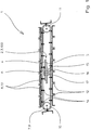
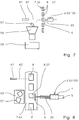
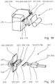
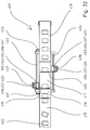
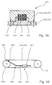
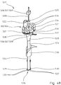
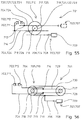
- an electromagnetic linear drive 3 is provided as a device 2 for accelerating a product 8 to be packaged (FIG. 1).
- the electromagnetic linear drive 3 consists of a movable part 4 and a part 5 driving the movable part 4.
- the movable part 4 which can be accelerated, moved uniformly and decelerated by the driving part 5 in the opposite direction by means of electromagnetic forces, is rigid with one Stamp 6 connected.
- a conveyor belt 9 is provided as a device 7 for guiding the moving product 8.
- the conveyor belt 9 runs around wheels 10, 11. It carries a large number of product receptacles 12.
- a tubular bag 13 is transported on each product receptacle 12.
- the product receptacles each have a mandrel 14 on the bottom side.
- the punch 6 is slit, grips one mandrel 14 and pushes the conveyor belt 9 forward by one cycle.
- a second electromagnetic linear drive 15 is also provided.
- the second linear drive 15 consists essentially of the movable part 16 and the driving part 17.
- the two linear drives 3, 15 are rigidly connected to one another in such a way that the driving part 5 of the first linear drive 3 is connected to the movable part 16 of the second linear drive 15 .
- the second linear drive 15 moves the first linear drive 3 against the conveyor belt 9 or away from it again, so that the plunger 6 grips the dome 14 or releases the mandrel 14 again.
- the stamp 6 on the linear drive 3 consequently moves along a path curve that describes a parallelogram.
- the linear drive 3 If the linear drive 3 has moved the conveyor belt 9 forward by one cycle, the linear drive 3 is reset by the movement of the second linear drive 15 to such an extent that the plunger 6 releases the mandrel 14. Then the movable part 4 of the linear drive 3 is moved under the next dome 14 and brought into engagement with this mandrel 14 by the second linear drive 15, whereupon the next cycle movement of the conveyor belt 9 takes place.
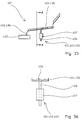
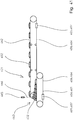
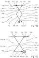
- the stamp 6 acts indirectly on the product 8 via the device 7 for guiding the moving product 8.
- the stamp 6 acts directly against the product 8 to be packaged.
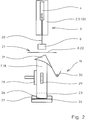
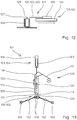
- the device 7 for guiding the moving product 8 is here the filling tube 18 of a vertical tubular bag machine 19.
- the stamp 6 is connected to the movable one via a rod 20 Part 3 of a linear drive 3 is connected and is thus axially movable from above into the filling tube 18.
- a placement station 21 for individual cardboard blanks 22 (FIG. 2) is located directly above the filling tube 18.
- the stamp 6 takes the cardboard blank 22 with it, presses it into the filling tube 18 by folding it in and places it on the bottom side in the film tube 23 surrounding the filling tube 18 (FIG. 3).
- the film tube 23 is cut by means of a piercing knife 24, so that open bags 25 with a stiffening cardboard blank 22 are produced.
- the bottom 26 of the bag 25 is welded by transverse sealing jaws 27.
- the longitudinal sealing of the film tube 23 is carried out by means of a longitudinal sealing jaw 28.
- the film transport is achieved by film withdrawals 29.
- the flat film web 30 is formed into a film tube 23 by means of a shaped shoulder 31.
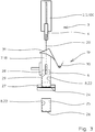
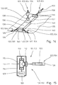
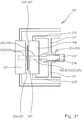
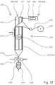
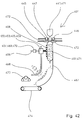
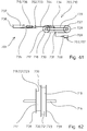
- the plunger 6 can be moved from above into a metering device 32.
- the linear drive 3 drives a rod 20 of the stamp 6 as a movable part 4.
- the dosing device 33 has a plurality of dosing chambers 33.
- By opening a device 34 by means of a linear drive 35 the product 8 present in the dosing chamber 33a is exposed to free fall.
- the product 8 falls into the filling tube 18 through a funnel 36.
- the plunger 6 acts through the open metering chamber 33a as far as into the filling tube 18, that is to say in the entire space 37 through which the product 8 falls.
- Further linear drives 38, 39 continue to rotate the metering device 32 in cycles or respectively Open and close retaining flaps 40 to prevent product 8 from trickling down from the filling tube 18.
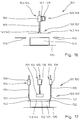
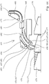
- a stamp 6 designed as a sieve 41 acts precisely in the filling tube 18 of a packaging system.
- the stamp 6 compresses and accelerates product swarms 42 during their free fall.
- the movement of the stamp 6 is realized by means of two electromagnetic linear drives 43, 44.
- a linear drive 43 is aligned parallel to the filling tube 18.
- the other linear drive 44 is aligned radially with respect to the filling tube 18.
- the fill tube 18 has an axially extending slot 45. At the beginning of the slot 45 and at the end of the slot 45, a tangential recess 46, 47 is provided in the filling tube 18.
- the stamp 6 is via a rod 48 guided in the slot 45 with the movable part 49 of the linear drive 44 aligned radially to the filling tube 18.
- the plunger 6 is removed radially from the filler tube 18 by the operation of the linear drive 44 from the lower recess 47, moved upwards by the operation of the linear drive 43, and inserted into the upper recess 46 by the operation of the linear drive 44 to the next swarm of product 42 to compress and accelerate. Compression of the product swarms 42 has the advantage that the product can be packaged faster and more securely.
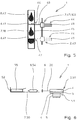
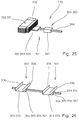
- the surface of a horizontally running conveyor belt 50 is provided as a device 7 for guiding the moving product 8.
- the stamp 6 can be moved in the horizontal direction and transverse to the direction of movement of the conveyor belt 50 by means of an electromagnetic linear drive 51.
- the punch 6 acts in the direction of a vertically oriented boundary 52 of the conveyor belt 50.
- the linear drive 51 is displaced parallel to the conveying direction by means of a further linear drive 53.
- the plunger 6 driven by the linear drive 51 pushes the product 8 configured as a tubular bag 54 into an open folding box 55.
- the boundary 52 serves as a stop for the folding box 55.
- the linear drive 53 moves the punch 6 during the insertion process with the conveyor belt 50 and resets the punch 6 together with the linear drive 51 for the insertion of the next tubular bag 54 against the transport direction.
- a stamp 6 which can be displaced in the horizontal direction can be moved into a product drop section 56 and thereby throws a defective product 57 out of a stream of freely falling products and into a funnel 58 of a disposal container 59.
- the linear drive 60 reacts to pulses from a sensor 61.
- the sensor 61 detects defective product 57 by means of a measuring beam 62.
- the product drop distance is the guide of the moved product 8 to be packaged.
- a stamp 6 which can be displaced in the horizontal direction transversely to a conveyor belt 64 by means of an electromagnetic linear drive 63 is provided in order to push defective product 57 from the conveyor belt 64 into a disposal container 59.
- the defective product 57 is recognized by the measuring beam 62 of a sensor 61.
- two horizontally aligned electromagnetic linear drives 66, 67 which act transversely to a conveyor belt 65 are provided.
- the stamp 6 of the one linear drive 66 is designed as the head 68 of a prospectus shooter 69 and shoots prospectuses 70, which are stored at a prospectus depositing point, individually into open folding boxes 55.
- the folding boxes 55 provided with brochures 70 are taken from the conveyor belt 65 of a closing station (not in the drawing) shown) and closed there. Folding boxes 55, which have passed through the closing station and still remained unlocked, are recognized by the measuring beam 62 of a sensor 61 and pushed by the conveyor belt 65 by the linear drive 67.
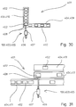
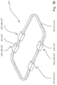
- a closing device 101 essentially consists of a closing mechanism 102 as a device 100 and a drive 103 for the closing mechanism 102 (FIG. 10).
- the drive 103 is an electromagnetic linear drive 104 with a movable part 105 and a part 106 driving the movable part 105.
- the closing mechanism 102 consists of a linkage 107 and transverse jaws 109 connected to the linkage 107 via springs 108.
- the transverse jaws 109 serve as a transverse jaw closing device 110 the top and bottom seam welding on a vertical tubular bag machine. Due to the relative movement of the driving part 106 and the moving part 105, the cross jaws 109 are moved towards one another and reset again.
- the movable part 105 of an electromagnetic linear drive 104 is connected to a piston 112 sliding in a pressure transmission device 111.
- the cross jaws 109 of the cross jaw locking device 110 are each connected to a piston 113, 114.
- the pistons 113, 114 are also displaceable in the pressure transmission device 111.
- the pressure transmission device 111 is sealed and contains a gas 115. The movement of the piston 112 driven by the linear drive 104 accelerates or decelerates the pistons 113, 114 by the gas pressure, as a result of which the transverse jaws 109 are moved towards one another and reset again.
- two gusset plungers 116 are provided on a cross jaw closing device 110. Each gusset plunger 116 is driven by an electromagnetic linear actuator 104. A flat film web 117 is formed on a shape shoulder 118 to form a film tube 119 around a filling pipe 124 reshaped, transported further by film transport devices 120 and welded transversely by means of cross jaws 109. The longitudinal seam 121 of the film tube 119 is welded by a longitudinal welding device 122. The side gusset piercers 116 create side gussets 123 in the tubular bags to be produced.
- the movable part 105 of an electromagnetic linear drive 104 is designed as a bag flag flipper 125.
- a cup belt 126 guides bag 127 with a flag 128 at the end to the bag flag flipper 125.
- the flag 128 is flipped over by a movement of the movable part 105 relative to the driving part 106.
- the movable part 105 of an electromagnetic linear drive 104 is connected to a plunger 129.
- the stamp 129 can be displaced vertically in a filling tube 124 of a vertical tubular bag machine 130.
- Cross jaws 109 are provided below the filling tube 124 and form a mechanical resistance against the plunger 129.
- the stamp 129 is moved against the bottom 131 of the film tube 119 between two filling processes.
- One of the transverse jaws 109 rotating about axes 132 welds the bottom-side flag 128 against the film tube 119.
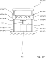
- three tab closers 133 and a bag insert 134 are each driven by an electromagnetic linear drive 104.
- the movable part 105 is connected to a tab closer 133 or the bottom insert 134.
- a conveyor belt 135 is provided for feeding open folding boxes 136 to the tab closer 133.
- a strap closer 133 acts as a cover strap closer 137 vertically against the conveyor belt and folds over the cover straps 138.
- Two tab closers 133 act as side tab closers 139 parallel to the surface of the conveyor belt 135 for the purpose of closing the side tabs 140.
- the movable part 105 of an electromagnetic linear drive 104 is connected to a gripper 141.
- the gripper 141 is a vacuum gripper 142 and grips in each case a cut 143 of a lid 144 for covering a box 145 which is open at the top.
- the box 145 is sprayed with glue at the top by means of glue application nozzles 146.
- the driving part 106 of the linear drive 104 is aligned vertically and with the movable part 147 a horizontally aligned further electromagnetic linear drive 148.
- the driving part 149 of the further linear drive 148 is stationary.
- the one linear drive 104 can be displaced in parallel in the horizontal direction by the other linear drive 148, and the gripper 141 can carry out a combined movement, in which it grips a blank 143 from a depot (not shown), the blank 143 on a box 145 proposes, and the blank 143 sets on the box 145.
- FIG. 18 A combination of two electromagnetic linear drives 104, 148 analogous to FIG. 16 is shown in FIG. 18 for a cross jaw 109.
- the cross jaw 109 can thereby perform a wide variety of movements in space.
- the conveyor belt 135 transports the box 145 with a blank 143 attached to a capping station 150 (FIG. 17).
- a capping station 150 At the capping station 150, vertically movable tab folders 141 are provided by means of electromagnetic linear drives 104 in order to fold the tabs 152 of the lid 144 and to press them against the glued upper edge of the box 145.
- an electromagnetic linear drive 205 which can also be referred to as a linear motor, is used as the drive 204, with a movable part 206 and one which drives the movable part 206 Part 207 provided ( Figure 19).
- the movable part 206 is connected to the separating device 203.
- the separator 203 is a tangential, i.e. H. here, web cutter 209 movable transversely to a film web 208.
- the web cutter 209 is guided along a straight guide 210.
- the web cutter 209 is provided on the film feed 211 of a tubular bag machine (not shown in the drawing).
- a fold edge 212 is provided on a rod 213 of rectangular cross section parallel to the guide 210.
- the fold edge 212 serves to slightly fold the film web 208.
- a blade 214 of the web cutter 209 can be moved along the fold edge 212 and cuts through the film web 208 along this path.
- a web cutter 209 is used in particular when replacing supply rolls 215.
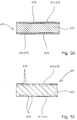
- a piercing knife 216 with teeth 217 is provided as the separating device 203.
- the toothing 217 is aligned in the separating direction.
- the piercing knife 216 can be displaced in a recess 219 in a transverse jaw 218 of a tubular bag machine (not shown in the drawing) and serves to cut through a film tube 220.
- a relative seam of the hot transverse jaw 218 and a transverse jaw 221 opposite to this transverse jaw 218 make a top seam 222 and a Bottom seam 223 welded into the film tube 220.
- the piercing knife 216 cuts through the film tube 220, so that a previously filled bag 224 is cut off.
- the piercing knife 216 is connected to a movable part 206 of an electromagnetic linear drive 205.
- the movable part 206 is driven by a stationary, driving part 207.
- the separating device 203 is a punch punch 225 in a transverse jaw 218 of a tubular bag machine (not shown in the drawing).
- a weld surface 226 producing a top seam 222 and a weld surface 227 producing a bottom seam 223 are provided on the transverse jaw 218 (analogously to FIG. 20).
- the punch punch 225 is guided perpendicular to the welding surface 226 for the head seam 222 and perpendicularly through this by means of a guide 228.
- the punch punch 225 gets somewhat into the further guide 228 in the second cross jaw 221.
- the guide 228 is a recess 229 in each case, and the punch punch 225 is designed as a bolt 230.
- the bolt 230 is rigidly connected to the movable part 206 of an electromagnetic linear drive 205.
- the movable part 206 is driven by the driving part 207.
- the driving part 207 of the electromagnetic linear drive 205 is rigidly connected via a connection 231 to a carrier 232 of a cross jaw 218, the movable part 206 of the linear drive 205 is movable and rigidly connected to the punch punch 225 with respect to the driving part 207.
- the hole punch 225 is arranged centrally with respect to the length of the cross jaws 218, 221.
- the punch punch 225 has teeth 217.
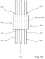
- an electromagnetic linear drive 305 also called a linear motor, is provided as device 304 for moving (FIG. 22) .
- the linear drive 305 consists of essentially of a movable part 306 and a part 307 driving the movable part 306.
- the movable part 306 can be connected to the device 303 for taking away.
- a conveyor belt 308 is provided as a device 303 for taking the packaging material.
- Driving surfaces 309 are provided on the conveyor belt 308.
- the movable part 306 of the linear drive 305 acts against a driving surface 309 of the conveyor belt 308 in the direction of transport of the conveyor belt 308 and thus takes packaging material (not shown in the drawing) on the conveyor belt.
- the conveyor belt 378 is supported by rollers 310.
- a total of two electromagnetic linear drives 305, 311 are provided, the driving part 307 of one linear drive 305 being rigidly connected to the movable part 312 of the other linear drive 311.
- the movable parts 306, 312 of the linear drives 305, 311 can be displaced in directions that run in one plane and perpendicular to one another.
- the driver 314 is set to the right by a subsequent resetting of the movable part 306 relative to the driving part 307.
- the linear drive 305 is connected via an electrical line 315 to a vibrating frequency transmitter 316.
- the vibrating frequency transmitter 316 serves to operate the linear drive 305 stuttering and thus ensures compression of compressible product which is transported in packaging on the conveyor belt 308.
- the device 303 for taking away the packaging material 302 is a film take-off 317 of a vertical tubular bag machine 318.
- the film take-off 317 acts against the filling tube 319.
- the movable part 306 of the linear drive 305 can be moved parallel to the central axis 328 of the filling tube 319.
- Suction nozzles 320 of a vacuum pump serve as the device 303 for taking the packaging material 302.
- the packaging material 302 is a film web 321, which is formed on a shaping shoulder 322 to form a film tube 323 and is welded lengthwise by means of a longitudinal sealing jaw 324.
- the film feed occurs in such a way that the film withdrawal 317 from an upper position (solid lines in FIG. 23) is moved into a lower position (broken lines in FIG. 23) by the linear drive 305.
- the suction nozzles 320 hold the film tube 323 under vacuum and pull it down.
- excess pressure is applied to the suction nozzles 320, the film tube 323 is thus pushed off the film take-off 317, and then the film take-off 317 is moved back into the upper position.
- the height difference between the upper and the lower position corresponds to the length of a tubular bag 325.
- the tubular bag machine 318 operates in a clocked manner.
- the film tube 323 is welded cross-wise by means of transverse jaws 326 and the film tube 323 is severed by means of a piercing knife 327.
- the tubular bag 325 produced is filled in portions through the filling tube 319.
- the tip 329 of a cut separator 330 is provided as a device 303 for taking the packaging material 302 away.
- the tip 329 is mechanically connected to the movable part 306 of the linear drive 305.
- the driving part 307 of the linear drive 305 moves the tip 329 against a stack 331 of a magazine (not shown) of flat cardboard blanks 332 and pushes out on the stack 331 to a cardboard blank 332 from the stack 331 with each movement.
- the movable part 306 is identical to the driving part 307 of the linear drive 305.
- the moving and driving part 306, 307 floats along a guide 333.
- the guide 333 is designed as a rod 334.
- the driving parts 307 and the linear drives 305 are each at the same distance from one another.
- a platform 335 is attached to the movable and driving part 306, 307 at the top as a device 303 for taking away. Platforms 335 are used to hold packaging material (not shown in the drawing). Transversely to the direction of movement and perpendicular to the platform 335, 335 supports are attached to each platform to secure the packaging material.
- a punch 337 connected to the movable part 306 of a linear drive 305 is provided as a device 303 for taking the packaging material 302.
- suction nozzles 338 for receiving and releasing cardboard blanks 332.
- the punch 337 can be moved vertically from above into a mold shaft 339 by operating the driving part 307 of the linear drive 305.
- By moving a further linear drive 311 along a rod 340 the entirety of linear drive 305 and punch 337 can be moved horizontally.
- the stamp 337 first grips a glued cardboard blank 332 by means of negative pressure, then brings it to the position shown in FIG. 27 by means of a horizontal movement and finally pushes it downward through the form shaft 339. While a glued cardboard falls out of the form shaft 339 below, the stamp becomes 337 for a further cardboard blank 332.
- a label driver 341, 342 is provided as a device 303 for taking away, one label driver 341 passing the labels 343 on to the other label driver 342.
- One label driver 341 is configured on the label side in the form of a line 344 and in each case pushes a label 343 out of a magazine 345.
- the second label driver 342 is flat on the label side and is designed with a contact surface 346 for continuing the labels 343.
- a suction nozzle 347 of a vacuum pump is provided in the label driver 342. The suction nozzle 347 opens into the contact surface 346.
- a label 343 is held on the contact surface 346 by means of negative pressure, pressed against a glued package 348 and released from the contact surface 346 by positive pressure from the suction nozzle 347.
- the device 303 for taking the packaging material 302 with it is a horizontally displaceable plate 349, above which a product delivery point 350 is located.
- tubular bags 325 are delivered from a conveyor belt 351 via a slide 353 into a collecting container.
- the plate 349 together with the collecting container 352 is shifted to the right by one bag thickness immediately in front of each incoming tubular bag 325.
- the linear drive 311 serves as a device 304 for moving the packaging material 302 carried along. Its driving part 313 drives a movable part 312. Between the movable part 312 and the plate 349 there is a linear drive 305.
- the driving part 307 of the linear drive 305 is rigidly connected to the movable part 312 of the linear drive 311. If a row of tubular bags 325 has been introduced into the collecting container 352, the linear drive 305 displaces the plate 349 together with the collecting container 352 by one bag width parallel to the first row in order to produce a further row of tubular bags 325.
- a transport device 401 for product 402 to be packed consists of a device 403 as device 100 for moving the product 402 and a device 404 for guiding the moving product 402 (FIG. 30).
- An electromagnetic linear drive (linear motor) with a movable part 406 and a part 407 driving the movable part 406 is provided as the device 403 for movement.
- the movable part 406 is movable on the device 404 for guidance.
- the movable part 406 is rigidly connected to a stamp 408.
- the stamp 408 acts against the product 402.
- Two conveyor belts 409, 410 arranged at right angles to one another are provided as a device 404 for guiding the moving product 402.
- One conveyor belt 409 conveys the other conveyor belt 410.
- the stamp 408 can be moved transversely to the conveying conveyor belt 409 and onto the conveying conveyor belt 410 and pushes an incoming product 402 extremely quickly from the conveyor belt 409 onto the conveyor belt 410. After each displacement process, the stamp 408 is returned to its starting position just as quickly.
- a stamp 408 can be moved transversely to a conveyor belt 411 and two further conveyor belts running parallel to the first conveyor belt 411 and distributes product 402 from the conveyor belt 411 evenly.
- the transport device 401 can also be designed as a product synchronizer 414 (FIG. 32, FIG. 33).
- the product synchronizer 414 moves product 402 guided on conveyor belts 415, 416, 417, 418 in the conveying direction in such a way that the same distance is achieved between two products 402.
- Two punches 419, 420 can be moved parallel to and on the conveyor belt 417 and height-adjustable relative to the conveyor belt 417.
- Sensors 421, 422 for detecting the positions of the products 402 are provided on the transport device 401.
- the speed of the conveyor belt 417 is significantly faster than the speed of the Conveyor belt 416 to increase the distance between the incoming products 402. This is particularly important for products 402 lying particularly close together.
- the conveyor belt 417 has a well slidable surface, along which the product 402 is displaced in the conveying direction with the aid of a plunger 419, so that the products 402 on the conveyor belt 418 are each at the same distance.
- the shift occurs in accordance with the measured values from sensor 421 and is controlled by sensor 422.
- the stamps 419, 420 work alternately.
- a displacement is realized in such a way that an electromagnetic linear drive 405, 422, in which the driving part 407 is identical to the movable part 406, is displaced along a guide rod 423, 424.
- the stamp 419, 420 is displaced upward by means of an electromagnetic linear drive 425, 426.
- the driving part 407 is also the same as the movable part 406, and the displacement of the movable part 407 runs along a guide rod 427, 428.
- the raised punch 419, 420 is returned to a starting position via the product 402, lowered and then shifts the next product 402.
- a stamp 408 can be adjusted in height in a filling shaft 429 by means of a linear drive 405.
- a height measuring device 430 with an ultrasonic sensor 431 measures the filling height in the filling shaft 429.
- a circumferential product feed device 432 throws product 402 into the filling shaft 429 via a slide 434.
- the height measuring device 430 and the linear drive 405 always ensure the same height of the upper surface 433 of the uppermost product 402 in the filling shaft 429, with which each falling product 402 suffers the same fall height and thus the same fall time.
- a conveyor trough 435 is provided as a device 404 for guiding the moving product 402.
- the movable part 406 of an electromagnetic linear drive 405 can be moved perpendicular to the conveying direction and is rigidly connected to the device 404.
- the linear drive 405 shakes the conveyor trough 435 and ensures a uniform product flow 436 into a container 437.
- a filling pipe 438 which is divided in two in the vertical direction is provided as the device 404 for guiding the moving product 402.
- the filling tube 438 is part of a vertical tubular bag machine 439.
- One of the two filling tube parts 440, 441 can be displaced horizontally by means of a linear drive 405.
- the fill tube 438 is only expanded during the free fall of the product 402.
- the filling tube part 441 is placed again against the other filling tube part 440, the film tube 443 is longitudinally welded by means of a longitudinal sealing jaw 444 and transversely by means of transverse sealing jaws 445, 446, and separated with a separating knife 447 and further pulled off from a film roll 448.
- the movable part 406 is always the same as the driving part 407 of the linear drive 405.
- a circumferential path 449 is provided as the device 403 for guiding.
- the upper area 450 of each movable part 406 is designed as a platform 451 and serves to transport product (not shown).
- an interconnect 452 is inserted into the track 449, which is used via a single car coding 453 and a pole control 454 for the precise displacement of the moving parts 406.
- a conveyor belt 455 runs around two wheels 456, 457.
- a wheel 456 is connected to the movable part 406 of an electromagnetic linear drive 405 via a joint 459 arranged on the wheel rim 458 and a joint mechanism 460.
- the linear drive 405 drives the conveyor belt 455 in this way.
- a rotating conveyor belt 461 is provided as a device 4 for guiding the moving product 402.
- a further circulating conveyor belt 462 is provided above the conveyor belt 461.
- the rotational speed of the upper conveyor belt 462 is greater than that of the lower conveyor belt 461. This results in the scaled arrangement of the product 402 on the lower conveyor belt 461.
- the conveyor belts 461, 462 are each driven in that the movable part 406 of a linear drive 405 is part 464 of a rotating conveyor belt 461, 462.
- the conveyor belts 461, 462 become like this driven.
- a sensor 465 with its measuring beam 466 determines the position of the incoming products 402 and thus serves to coordinate the rotational speed of the lower conveyor belt 461 with the incoming product 402.
- the movable part 406 of an electromagnetic linear drive 405 can be displaced parallel to a wall 467 and along a guide 468.
- the movable part 406 has a stamp 408 directed against the wall 467.
- a pressure device 469 is provided on the movable part 406 transversely to the direction of displacement. The pressure device 469 serves to clamp a product 402 with the stamp 408 against the wall 467.
- An electromagnetic linear drive 470 is provided as the printing device 469.
- Loot 471 of a tubular bag machine is freed of excess air by means of air ejectors 472, welded by means of transverse sealing jaws 445, 446, separated from a film tube 443 by a separating knife 447 and fed to a system of opposing belts 473, 474 along the wall 467 to prevent a teardrop-shaped bag shape in the flattened state (dashed: further position of the stamp 408).
- the stamp 408 is set back along the guide 468 for receiving the next bag 471.
- the guide 475 can also be circumferential (FIG. 43).
- the bags 471 at the end 476 of a wall 467 in a flat state are dispensed at a feed device 477 for collecting containers 478 into a collecting container which is moved past.
- a prey 471 arrives here via a system of opposing chains 479, 480 via a conveyor belt 481 into a shaft 482 between a circumferential wall 467 and a stamp 408 which can be displaced along a guide 468.
- the pressure on the bag 471 in the shaft 482 is exerted by a spring 483 a linear drive 485 movable along a guide 484 against the circumferential wall 467.
- the welded end 486 of a film tube 443 of a vertical tubular bag machine (not shown) is provided as means 404 for guiding the moving product 402.
- a product scraper 487 is connected to the movable part 406 of an electromagnetic linear actuator 405.
- the driving part 407 of the linear drive 405 is in operation, the movable part 406 is first moved downwards, whereby the legs 488 of the linkage 489 are pressed together by the fixed rollers 490 and the joint 491 against the force of the spring 492.
- the rollers 493 on the legs 488 move towards each other and downwards and thereby graze down the product 402 contained in the film tube 443 downwards.
- the product stripper 487 is opened again for the next product portion and brought into its upper position.
- a device 501 for metering flowable product 502 consisting of a storage vessel 503, a volume metering device 504 as device 100 and a displacement mechanism 505 with drive 506 for displacing the volume metering device 504,
- the drive 506 is an electromagnetic linear drive 407 with a movable part 508 and one of these movable part 508 driving part 509 ( Figure 46).
- the movable part 508 is rigidly connected to the displacement mechanism 505 of the volume metering device 504.
- the volume metering device 504 contains two metering chambers 510, 511 which can be displaced below two outlets 512, 513 of the storage vessel 503 with the shifting mechanism 505.
- the dosing chambers 510, 511 are delimited in the direction of displacement by the closing bodies 514, 515.
- one closure body 514, 515 closes an outlet 512, 513 during the filling of a dosing chamber 510, 511.
- a passage 517 for dispensing product 502 is provided in a closure part 516, through which product 502 downwards falls into a vertical filling tube 518 of a tubular bag machine.
- the metering chambers 510, 511 and the closing bodies 514, 515 form a single component 519.
- the closing mechanism 505 can be displaced in a straight line. During the filling of a dosing chamber 510, 511, the product 502 is always discharged from the other dosing chamber 510, 511 down into the filling tube 518.
- the metering chambers 510 are arranged in a sliding mechanism 505 designed as a rondelle.
- the Rondell 520 can be rotated in a circle.
- Cams pointing radially outward are provided on the roundel 520.
- Each cam 521 is radially assigned to a metering chamber 510.
- the movable part 508 of an electromagnetic linear drive 507 pushes against a cam 521 by reciprocating movement and thereby rotates the rondel 521 by a defined angle.
- the dosing chambers 510 are filled on a hose 522 connected to a storage vessel, moved in the filled state in two cycles over the passage 517 of the closure part 516, and there the dosed product is fed via a funnel 523 and a tube 524 into the filling tube 518 of a vertical tubular bag machine submitted.
- a plunger 525 connected to the movable part 508 of an electromagnetic linear drive 507 can be moved from above into the metering chamber 510, which is located at the passage 517, and additionally accelerates the product in this metering chamber 510 during its free fall.
- Two retaining flaps 526, 527 are provided directly below the fill pipe 518 for closing the fill pipe 518.
- the retention flaps 526, 527 can be folded against the bottom opening 528 of the filling tube 518.
- the retaining flaps 526, 527 are each connected to the movable part 508 of an electromagnetic linear actuator 507 via a joint 529, 530. In their closed position (solid lines) they close the opening 528 and thus prevent product which trickles down from interfering with the sealing of transverse bag seams on the tubular bag machine. In their open position (broken lines) they open the opening 528.
- a movable part 604 of the linear drive 603 connected to the elements 602 is driven by a driving part 605 of the linear drive 603 (FIG. 49).
- the device 601 is a height adjustment device 606.
- Two guides 607, 608 for the movable part 604 are connected to the movable part 604 via the elements 602 and a web 616.
- Slide bearings 609, 610 serve as guides 607, 608.
- Each slide bearing 609, 610 has a vertically extending rod 611, 612 made of steel 613, on the jacket 614 of which an abrasion-reducing sliding surface 615 is provided.
- Each element 602 consists of steel 613 and slides with the aid of a passage 617, 618 on a sliding surface 615 of a rod 611, 612.
- the inner surfaces of the passages 617, 618 also have abrasion-reducing sliding surfaces 615.
- the distances between a guide 607, 608 and the movable part 604 are the same.
- There is an increased concentration of aluminum 619 on all sliding surfaces 615 (FIG. 51).
- the aluminum 619 was introduced into the steel 613 by means of ion implantation.
- the aluminum concentration is highest on the jacket 614 of the rods 611, 612. This is where the friction-reducing properties of steel 613 are greatest.
- diamond-like carbon 620 can also be applied to the steel 613 as the sliding surface 615 (FIG. 50).
- diamond-like carbon 620 has the advantage that its coefficient of friction is one of the lowest coefficients of friction of solids.
- the movable part 604 of the electromagnetic linear drive 603 is equal to the driving part 605 and the element 602 to be displaced.
- the driving part 605 acts against a rod 621 running centrally between the rods 611, 612. All rods 611, 612, 621 pass through the element 602. While the middle rod 621 serves to drive the element 602, the outer rods 611, 612 serve as guides 607, 608. Only the outer rods 611, 612 each have a sliding surface 615.
- the rod 622 passing through the element 602 in the middle serves as the guide 607, against which the driving part 605 of the electromagnetic linear drive 603 also acts.
- the rod 622 has a sliding surface 615 and has a precisely fitting seat in the element 602.
- the movable part 604 is horizontally displaceable and has a platform 623 rigidly connected to the movable part 604 for transporting goods (not shown in the drawing).
- the length of the movable part 604 in the direction of movement is more than twice as large as each of its dimensions in a plane perpendicular to the direction of movement, as a result of which the element 602 is particularly well guided.
- the drive 703 is an electromagnetic one Linear drive 707 with a movable part 708 and a driving part 709
- the gear 705 is a reduction gear 710 ( Figure 55).
- the driving force Part 709 is stationary relative to the moving components 702.
- Two components 702 are provided, which are connected to the transmission 705 as welding jaws 711, 712 via a fastening 713, 714 in each case.
- the linear drive 707 drives the gear 705 in a step-down ratio, although in principle it could also be used in a position (shown in dashed lines) without a step-down ratio.
- the transmission 705 contains two disks 717, 718 with different diameters that can be rotated about the same axis 716 and are rigidly connected to one another.
- Each disk 717, 718 has, along its jacket 719, 720, a driver device 721 in the form of a surface 723 encircling as a toothed surface 722.
- the toothed surface 722 receives racks 724 serving as connections 704, 706.
- the driver device 721 of the disk 718 with the larger diameter is in contact with the connection 706 to the drive 703, and the driver device 721 of the disk 717 with the smaller diameter is in contact with the connections 704 to the components 702.
- the ratio of the radii of the disks 717, 718 is the reduction ratio. It makes it possible to use a relatively low-power and therefore inexpensive linear drive 707 with sufficient power. The acceleration of the welding jaws 711, 712 is still extremely high despite the reduction.
- the disks 717, 718 are gear wheels 725, 726.
- two further disks 727, 728 which are rigidly connected to one another, are provided identically, offset parallel to the disks 717, 718.
- a smooth belt 729 runs around the small pulleys 717, 727 and another smooth belt 730 runs around the large pulleys 718, 728.
- the rigid connections 704 are connected to the circumferential belt 729 at the fastenings 713, 714.
- the rigid connection 706 connects the movable part 708 of the linear drive 707 to the rotating belt 730 via the fastening 731.
- the device 701 is designed as a height adjustment device 732.
- the gear 705 is configured analogously to the gear 705 in FIG. 56.
- the height of a component 702 is adjusted by means of a vertically aligned electromagnetic linear drive 707.
- a gear 705 similar to FIG. 56 also serves to move a component 702.
- Component 702 is connected here as stamp 733 to gear 705 via a fastening 734.
- the stamp 733 pushes an object 715 over a base 735.
- the object is a tubular bag 736.
- FIG. 62 shows the pulleys 717, 718 of FIG. 61 which are rigidly connected to one another and can be rotated about the axis 716. Their circumferential surfaces 723 are delimited by circumferential boundaries 739 for better guidance of a belt (not shown).
- the movable part 708 of an electromagnetic linear drive 707 can be moved perpendicular to a guide 740.
- Two components 702 can be displaced in opposite directions along the guide 740.
- the movable part 708 is connected to the components 702 via a joint mechanism 741.
- the joint mechanism 741 consists of a joint 742, which connects the struts 743, 744 with joints 745, 746 on the components 702.
- Favorable power transmissions are possible in particular for small angles ⁇ between the guide 740 and the struts 743, 744.
- the transmission 705 contains a pair of scissors 747 with two scissor-type buckets 748, 749.
- the components 702 which can be displaced along the guide 740 are connected to the scissor tips 750, 751 via joints 745, 746.
- the movable part 708 acts via the joint 742, the struts 752, 753 and the joints 754, 755 against the scissor ends 756, 757.
- the joints 754, 755 are adjustable along the scissor pool 748, 749 to change the reduction ratio.
- the direction of movement of the movable part 708 is perpendicular to the direction of displacement of the guide 740.
- the movable part 708 of the electromagnetic linear drive 707 can be moved parallel to the guide 740.
- the driving part 709 can be moved.
- the Scherenbeckes 748, 749 are connected to each other via a joint 758. While one scissor end 756 is connected to the movable part 708 via a joint 759 and a connection 706, the other scissor end 757 is connected to the driving part 709 via a joint 760.
- the device 701 is particularly suitable for small displacements of the components 702, since the linear drive 707 is only moved vertically to a small extent.
Landscapes
- Engineering & Computer Science (AREA)
- Mechanical Engineering (AREA)
- Containers And Plastic Fillers For Packaging (AREA)
Priority Applications (1)
| Application Number | Priority Date | Filing Date | Title |
|---|---|---|---|
| EP99121765A EP1001186B1 (fr) | 1995-09-23 | 1996-06-13 | Appareil pour déplacer des machoires de scellement |
Applications Claiming Priority (16)
| Application Number | Priority Date | Filing Date | Title |
|---|---|---|---|
| DE1995135439 DE19535439A1 (de) | 1995-09-23 | 1995-09-23 | Vorrichtung zum Verschieben mindestens eines Elements |
| DE19535438 | 1995-09-23 | ||
| DE19535438A DE19535438A1 (de) | 1995-09-23 | 1995-09-23 | Vorrichtung zum Bewegen mindestens eines Bauteils oder eines sonstigen Gegenstandes |
| DE19535439 | 1995-09-23 | ||
| DE1995135512 DE19535512A1 (de) | 1995-09-25 | 1995-09-25 | Vorrichtung zum Zuführen von Verpackungsmaterial |
| DE19535509 | 1995-09-25 | ||
| DE19535515 | 1995-09-25 | ||
| DE19535511 | 1995-09-25 | ||
| DE19535514A DE19535514B4 (de) | 1995-09-25 | 1995-09-25 | Transportvorrichtung für zu verpackendes Produkt |
| DE19535510A DE19535510B4 (de) | 1995-09-25 | 1995-09-25 | Verschließvorrichtung für einen Verpackungsvorgang |
| DE1995135515 DE19535515A1 (de) | 1995-09-25 | 1995-09-25 | Vorrichtung zur Dosierung fließfähigen Produkts |
| DE19535512 | 1995-09-25 | ||
| DE19535510 | 1995-09-25 | ||
| DE19535514 | 1995-09-25 | ||
| DE1995135509 DE19535509B4 (de) | 1995-09-25 | 1995-09-25 | Verpackungsvorrichtung mit einer Einrichtung zur Beschleunigung eines zu verpackenden Produkts |
| DE1995135511 DE19535511A1 (de) | 1995-09-25 | 1995-09-25 | Trennvorrichtung für Verpackungsmaterial |
Related Child Applications (1)
| Application Number | Title | Priority Date | Filing Date |
|---|---|---|---|
| EP99121765A Division EP1001186B1 (fr) | 1995-09-23 | 1996-06-13 | Appareil pour déplacer des machoires de scellement |
Publications (2)
| Publication Number | Publication Date |
|---|---|
| EP0764584A2 true EP0764584A2 (fr) | 1997-03-26 |
| EP0764584A3 EP0764584A3 (fr) | 1997-08-20 |
Family
ID=27570764
Family Applications (1)
| Application Number | Title | Priority Date | Filing Date |
|---|---|---|---|
| EP96109481A Ceased EP0764584A3 (fr) | 1995-09-23 | 1996-06-13 | Dispositif d'emballage |
Country Status (1)
| Country | Link |
|---|---|
| EP (1) | EP0764584A3 (fr) |
Cited By (15)
| Publication number | Priority date | Publication date | Assignee | Title |
|---|---|---|---|---|
| WO1999054206A1 (fr) * | 1998-04-21 | 1999-10-28 | Glopak Inc. | Ensacheuse lineaire ultrarapide et son mode de fonctionnement |
| EP1002724A1 (fr) * | 1998-11-19 | 2000-05-24 | Rovema Verpackungsmaschinen GmbH | Dispositif et procédé pour introduire un objet ou une pluralité d'objets dans un emballage |
| WO2000064753A1 (fr) * | 1999-04-26 | 2000-11-02 | International Paper Company | Machine a emballer |
| EP1495976A1 (fr) * | 2003-07-11 | 2005-01-12 | Rovema Verpackungsmaschinen GmbH | Dispositif pour souder un film tubulaire soufflé |
| DE10351567A1 (de) * | 2003-11-03 | 2005-06-02 | Cfs Germany Gmbh | Verpackungsmaschine mit einem Elektrolinearzylinder |
| DE102005021109A1 (de) * | 2005-05-06 | 2006-11-09 | Rovema - Verpackungsmaschinen Gmbh | Vorrichtung und Verfahren zum Bewegen eines Produktes |
| DE202008013097U1 (de) * | 2008-10-06 | 2010-02-25 | Haver & Boecker Ohg | Rotierende Füllmaschine |
| CN101875440A (zh) * | 2009-04-29 | 2010-11-03 | 克罗内斯股份公司 | 用于从移动的输送部件移除物体的装置和方法 |
| WO2015010804A1 (fr) * | 2013-07-24 | 2015-01-29 | Khs Gmbh | Module d'emballage sous film de colis en tant qu'élément d'une machine d'emballage et procédé afférent |
| WO2016045965A3 (fr) * | 2014-09-25 | 2016-06-02 | Hastamat Verpackungstechnik Gmbh | Procédé et dispositif pour la production d'unités de conditionnement |
| CN105857784A (zh) * | 2016-05-25 | 2016-08-17 | 佛山科学技术学院 | 一种快递自动包装方法和装置 |
| CN110481916A (zh) * | 2019-07-30 | 2019-11-22 | 王安岩 | 一种应用于成套产品的自动包装系统 |
| CN111391344A (zh) * | 2020-03-12 | 2020-07-10 | 大国重器自动化设备(山东)股份有限公司 | 一种口罩自动化生产设备及生产工艺 |
| CN113511372A (zh) * | 2021-08-04 | 2021-10-19 | 广东宏川环宇智能装备有限公司 | 可实时调节灌装量的灌装机构 |
| EP3599074B1 (fr) | 2018-07-27 | 2023-06-07 | SN Maschinenbau GmbH | Dispositif de fabrication de sachets à fond plat |
Citations (13)
| Publication number | Priority date | Publication date | Assignee | Title |
|---|---|---|---|---|
| US3589458A (en) * | 1965-08-11 | 1971-06-29 | Haver & Boecker | Apparatus for filling bags with bulk materials |
| FR2104954A1 (fr) * | 1970-09-03 | 1972-04-28 | Bardet Neyrin Rene | |
| DE7319615U (de) * | 1973-05-24 | 1973-08-30 | Hesser F Maschinenfabrik Ag | Schlauchbeutelmaschine, insbesondere zum Verpacken von zum Stauben neigenden Gutern |
| US4017001A (en) * | 1975-01-10 | 1977-04-12 | Maurice Barthalon | Electromagnetic system for propulsion and programmed positioning |
| US4625492A (en) * | 1984-04-27 | 1986-12-02 | Maj | Device for packing and in vacuo preserving, in a plastic wrapping, products sterilized in an autoclave |
| US4655266A (en) * | 1984-07-27 | 1987-04-07 | Societe de Fabrication d'Appareils Automatiques et Sirops dite F.A.A.S (S.a.r.l) | Beverage vending machine |
| EP0368016A2 (fr) * | 1988-10-18 | 1990-05-16 | Rovema Verpackungsmaschinen Gmbh | Machine de fabrication de sachets tubulaires |
| US5063803A (en) * | 1990-07-31 | 1991-11-12 | A. J. Panneri Enterprises, Inc. | Tape cutting and dispensing machine |
| EP0514313A2 (fr) * | 1991-05-13 | 1992-11-19 | Azkoyen Hosteleria, S.A. | Perfectionnements aux machines de vente automatiques pour la distribution des infusions de café |
| GB2256846A (en) * | 1991-06-21 | 1992-12-23 | Gd Spa | Securing wrapping material |
| EP0583864A1 (fr) * | 1992-08-17 | 1994-02-23 | Systems, Machines, Automation Components Corporation | Vérin pneumatique électrique |
| EP0623431A1 (fr) * | 1993-05-07 | 1994-11-09 | Walter Suter | Dispositif pour couper une bande continue de papier ainsi qu'une méthode pour sa mise en oeuvre |
| WO1996009784A1 (fr) * | 1994-09-28 | 1996-04-04 | Tetra Laval Holdings & Finance S.A. | Appareil de transport lineaire commande par courroie pour machine a emballer |
Family Cites Families (4)
| Publication number | Priority date | Publication date | Assignee | Title |
|---|---|---|---|---|
| JPS5221992A (en) * | 1975-08-12 | 1977-02-18 | Jiyuushiyou Hoso Syst Kk | Heat seal apparatus |
| SU1475779A1 (ru) * | 1987-07-27 | 1989-04-30 | Омский политехнический институт | Устройство дл резки стоп листового неметаллического материала |
| RU1824348C (ru) * | 1991-02-19 | 1993-06-30 | Специальное конструкторско-технологическое бюро "Техноприбор" | Устройство дл загибани клапанов картонных пачек |
| JPH0551087A (ja) * | 1991-08-19 | 1993-03-02 | Mitsubishi Heavy Ind Ltd | 液体充填包装ラインの容器搬送方法及び装置 |
-
1996
- 1996-06-13 EP EP96109481A patent/EP0764584A3/fr not_active Ceased
Patent Citations (13)
| Publication number | Priority date | Publication date | Assignee | Title |
|---|---|---|---|---|
| US3589458A (en) * | 1965-08-11 | 1971-06-29 | Haver & Boecker | Apparatus for filling bags with bulk materials |
| FR2104954A1 (fr) * | 1970-09-03 | 1972-04-28 | Bardet Neyrin Rene | |
| DE7319615U (de) * | 1973-05-24 | 1973-08-30 | Hesser F Maschinenfabrik Ag | Schlauchbeutelmaschine, insbesondere zum Verpacken von zum Stauben neigenden Gutern |
| US4017001A (en) * | 1975-01-10 | 1977-04-12 | Maurice Barthalon | Electromagnetic system for propulsion and programmed positioning |
| US4625492A (en) * | 1984-04-27 | 1986-12-02 | Maj | Device for packing and in vacuo preserving, in a plastic wrapping, products sterilized in an autoclave |
| US4655266A (en) * | 1984-07-27 | 1987-04-07 | Societe de Fabrication d'Appareils Automatiques et Sirops dite F.A.A.S (S.a.r.l) | Beverage vending machine |
| EP0368016A2 (fr) * | 1988-10-18 | 1990-05-16 | Rovema Verpackungsmaschinen Gmbh | Machine de fabrication de sachets tubulaires |
| US5063803A (en) * | 1990-07-31 | 1991-11-12 | A. J. Panneri Enterprises, Inc. | Tape cutting and dispensing machine |
| EP0514313A2 (fr) * | 1991-05-13 | 1992-11-19 | Azkoyen Hosteleria, S.A. | Perfectionnements aux machines de vente automatiques pour la distribution des infusions de café |
| GB2256846A (en) * | 1991-06-21 | 1992-12-23 | Gd Spa | Securing wrapping material |
| EP0583864A1 (fr) * | 1992-08-17 | 1994-02-23 | Systems, Machines, Automation Components Corporation | Vérin pneumatique électrique |
| EP0623431A1 (fr) * | 1993-05-07 | 1994-11-09 | Walter Suter | Dispositif pour couper une bande continue de papier ainsi qu'une méthode pour sa mise en oeuvre |
| WO1996009784A1 (fr) * | 1994-09-28 | 1996-04-04 | Tetra Laval Holdings & Finance S.A. | Appareil de transport lineaire commande par courroie pour machine a emballer |
Non-Patent Citations (5)
| Title |
|---|
| PATENT ABSTRACTS OF JAPAN vol. 001, no. 074 (M-026), 16.Juli 1977 & JP 52 021992 A (JIYUUSHIYOU HOSO SYST KK), 18.Februar 1977, * |
| PATENT ABSTRACTS OF JAPAN vol. 017, no. 358 (M-1440), 7.Juli 1993 & JP 05 051087 A (MITSUBISHI HEAVY IND LTD), 2.März 1993, * |
| RENTZSCH: "Handbuch f}r Elektromotoren" , BROWN BOVERI & CIE , MANNHEIM XP002033012 2., Neubearbeitete Auflage * Seite 309, Zeile 5 - Zeile 10 * * |
| SOVIET PATENT ABSTRACTS Section PQ, Week 9005 14.März 1990 Derwent Publications Ltd., London, GB; Class P62, AN 90-035885 XP002033263 & SU 1 475 779 A (OMSKIJ POLT INST) , 30.April 1989 * |
| SOVIET PATENT ABSTRACTS Section PQ, Week 9445 4.Januar 1995 Derwent Publications Ltd., London, GB; Class Q31, AN 94-364810 XP002033262 & SU 1 824 348 A (SP KT B TEKHNOPRIOR) , 30.Juni 1993 * |
Cited By (24)
| Publication number | Priority date | Publication date | Assignee | Title |
|---|---|---|---|---|
| WO1999054206A1 (fr) * | 1998-04-21 | 1999-10-28 | Glopak Inc. | Ensacheuse lineaire ultrarapide et son mode de fonctionnement |
| GB2343877A (en) * | 1998-04-21 | 2000-05-24 | Glopak Inc | High speed linear bagging machine and method of operation |
| GB2343877B (en) * | 1998-04-21 | 2002-07-03 | Glopak Inc | High speed linear bagging machine and method of operation |
| US6421984B1 (en) | 1998-04-21 | 2002-07-23 | Glopak, Inc. | High speed linear bagging machine and method of operation |
| EP1002724A1 (fr) * | 1998-11-19 | 2000-05-24 | Rovema Verpackungsmaschinen GmbH | Dispositif et procédé pour introduire un objet ou une pluralité d'objets dans un emballage |
| WO2000064753A1 (fr) * | 1999-04-26 | 2000-11-02 | International Paper Company | Machine a emballer |
| US6625517B1 (en) | 1999-04-26 | 2003-09-23 | Emil D. Bogdanov | Position feedback system and method for use thereof |
| EP1495976A1 (fr) * | 2003-07-11 | 2005-01-12 | Rovema Verpackungsmaschinen GmbH | Dispositif pour souder un film tubulaire soufflé |
| DE10351567B4 (de) * | 2003-11-03 | 2017-06-22 | Gea Food Solutions Germany Gmbh | Thermoformer mit einem Elektrolinearzylinder |
| DE10351567A1 (de) * | 2003-11-03 | 2005-06-02 | Cfs Germany Gmbh | Verpackungsmaschine mit einem Elektrolinearzylinder |
| DE102005021109A1 (de) * | 2005-05-06 | 2006-11-09 | Rovema - Verpackungsmaschinen Gmbh | Vorrichtung und Verfahren zum Bewegen eines Produktes |
| DE202008013097U1 (de) * | 2008-10-06 | 2010-02-25 | Haver & Boecker Ohg | Rotierende Füllmaschine |
| CN101875440A (zh) * | 2009-04-29 | 2010-11-03 | 克罗内斯股份公司 | 用于从移动的输送部件移除物体的装置和方法 |
| CN101875440B (zh) * | 2009-04-29 | 2015-08-12 | 克罗内斯股份公司 | 用于从移动的输送部件移除物体的装置和方法 |
| CN105129403A (zh) * | 2009-04-29 | 2015-12-09 | 克罗内斯股份公司 | 用于从移动的输送部件移除物体的装置和方法 |
| WO2015010804A1 (fr) * | 2013-07-24 | 2015-01-29 | Khs Gmbh | Module d'emballage sous film de colis en tant qu'élément d'une machine d'emballage et procédé afférent |
| US10450094B2 (en) | 2013-07-24 | 2019-10-22 | Khs Gmbh | Film wrapping module for containers as a component of a packaging machine, and method thereof |
| CN106794910A (zh) * | 2014-09-25 | 2017-05-31 | 哈斯塔玛特包装技术有限公司 | 用于制造包装单元的方法和装置 |
| WO2016045965A3 (fr) * | 2014-09-25 | 2016-06-02 | Hastamat Verpackungstechnik Gmbh | Procédé et dispositif pour la production d'unités de conditionnement |
| CN105857784A (zh) * | 2016-05-25 | 2016-08-17 | 佛山科学技术学院 | 一种快递自动包装方法和装置 |
| EP3599074B1 (fr) | 2018-07-27 | 2023-06-07 | SN Maschinenbau GmbH | Dispositif de fabrication de sachets à fond plat |
| CN110481916A (zh) * | 2019-07-30 | 2019-11-22 | 王安岩 | 一种应用于成套产品的自动包装系统 |
| CN111391344A (zh) * | 2020-03-12 | 2020-07-10 | 大国重器自动化设备(山东)股份有限公司 | 一种口罩自动化生产设备及生产工艺 |
| CN113511372A (zh) * | 2021-08-04 | 2021-10-19 | 广东宏川环宇智能装备有限公司 | 可实时调节灌装量的灌装机构 |
Also Published As
| Publication number | Publication date |
|---|---|
| EP0764584A3 (fr) | 1997-08-20 |
Similar Documents
| Publication | Publication Date | Title |
|---|---|---|
| EP0029096B1 (fr) | Dispositif et procédé pour la fabrication d'emballages remplis d'un produit liquide | |
| DE19838076B4 (de) | Verfahren und Vorrichtung zum Herstellen von (Groß-)Packungen | |
| EP0137334B1 (fr) | Dispositif pour la fabrication d'emballages, notamment de cartouches de cigarettes | |
| EP0764584A2 (fr) | Dispositif d'emballage | |
| EP2524874B1 (fr) | Dispositif et procédé destinés à l'emballage de produits en pièces | |
| DE69029000T2 (de) | Vorrichtung und Verfahren zum Zusammenstellen von blattförmigem Material | |
| CH660161A5 (de) | Schlauchbeutelmaschine mit verschliesswerkzeugen. | |
| DE2352666B2 (de) | Vorrichtung zum Verpacken von flachen Gegenständen, wie Beutel, Müllsäcke o.dgl. in Verpackungsbeutel | |
| DE69104553T2 (de) | Vorrichtung zum Herstellen von Kartons aus flachen hülsenartigen Zuschnitten. | |
| DE19630420B4 (de) | Verfahren zum Betreiben einer Schlauchbeutelmaschine | |
| DE19535509B4 (de) | Verpackungsvorrichtung mit einer Einrichtung zur Beschleunigung eines zu verpackenden Produkts | |
| DE2943882A1 (de) | Verpackungseinrichtung | |
| DE19535514A1 (de) | Transportvorrichtung für zu verpackendes Produkt | |
| EP0711707B1 (fr) | Dispositif pour alimenter une machine d'emballage | |
| EP4046916B1 (fr) | Procédé et dispositif de formation d'empilements d'emballage | |
| DE2730799C2 (de) | Vorrichtung zum Einbringen von gefüllten Flachbeuteln in Kartons | |
| DE2934834C2 (de) | Vorrichtung zur Herstellung von Stangenpackungen aus vorzugsweise einzeln eingewickelten Bonbons o.ä. Süßwarenstücken. | |
| CH391561A (de) | Maschine zum Herstellen von gefüllten Packungen, insbesondere Flüssigkeitspackungen | |
| DE19808789B4 (de) | Schlauchbeutelmaschine | |
| DE19535512A1 (de) | Vorrichtung zum Zuführen von Verpackungsmaterial | |
| WO2000015501A1 (fr) | Procede et dispositif d'ouverture et de remplissage de sachets d'emballage prefabriques | |
| EP0768242A1 (fr) | Dispositif pour la fermeture de sacs remplis ouverts | |
| DE102004028212A1 (de) | Vorrichtung zum Übergeben von Blisterstreifen aus einer Stanzeinrichtung an eine Fördereinrichtung | |
| EP1422140B1 (fr) | Dispositf et procédé pour le remplissage d'une machine de cartonnage continue | |
| DE3936320C2 (fr) |
Legal Events
| Date | Code | Title | Description |
|---|---|---|---|
| PUAI | Public reference made under article 153(3) epc to a published international application that has entered the european phase |
Free format text: ORIGINAL CODE: 0009012 |
|
| 17P | Request for examination filed |
Effective date: 19960614 |
|
| AK | Designated contracting states |
Kind code of ref document: A2 Designated state(s): DE ES FR GB IT |
|
| PUAL | Search report despatched |
Free format text: ORIGINAL CODE: 0009013 |
|
| AK | Designated contracting states |
Kind code of ref document: A3 Designated state(s): DE ES FR GB IT |
|
| 17Q | First examination report despatched |
Effective date: 19990506 |
|
| STAA | Information on the status of an ep patent application or granted ep patent |
Free format text: STATUS: THE APPLICATION HAS BEEN REFUSED |
|
| 18R | Application refused |
Effective date: 20010419 |