EP0762563A2 - Douille de lampe anti-déflagrante avec, facultativement, des contacts à ouverture ou fermeture - Google Patents
Douille de lampe anti-déflagrante avec, facultativement, des contacts à ouverture ou fermeture Download PDFInfo
- Publication number
- EP0762563A2 EP0762563A2 EP96107321A EP96107321A EP0762563A2 EP 0762563 A2 EP0762563 A2 EP 0762563A2 EP 96107321 A EP96107321 A EP 96107321A EP 96107321 A EP96107321 A EP 96107321A EP 0762563 A2 EP0762563 A2 EP 0762563A2
- Authority
- EP
- European Patent Office
- Prior art keywords
- lamp
- contact
- lamp holder
- holder according
- opening
- Prior art date
- Legal status (The legal status is an assumption and is not a legal conclusion. Google has not performed a legal analysis and makes no representation as to the accuracy of the status listed.)
- Granted
Links
Images


Classifications
-
- H—ELECTRICITY
- H01—ELECTRIC ELEMENTS
- H01R—ELECTRICALLY-CONDUCTIVE CONNECTIONS; STRUCTURAL ASSOCIATIONS OF A PLURALITY OF MUTUALLY-INSULATED ELECTRICAL CONNECTING ELEMENTS; COUPLING DEVICES; CURRENT COLLECTORS
- H01R33/00—Coupling devices specially adapted for supporting apparatus and having one part acting as a holder providing support and electrical connection via a counterpart which is structurally associated with the apparatus, e.g. lamp holders; Separate parts thereof
- H01R33/945—Holders with built-in electrical component
- H01R33/96—Holders with built-in electrical component with switch operated by engagement or disengagement of coupling
-
- H—ELECTRICITY
- H01—ELECTRIC ELEMENTS
- H01R—ELECTRICALLY-CONDUCTIVE CONNECTIONS; STRUCTURAL ASSOCIATIONS OF A PLURALITY OF MUTUALLY-INSULATED ELECTRICAL CONNECTING ELEMENTS; COUPLING DEVICES; CURRENT COLLECTORS
- H01R33/00—Coupling devices specially adapted for supporting apparatus and having one part acting as a holder providing support and electrical connection via a counterpart which is structurally associated with the apparatus, e.g. lamp holders; Separate parts thereof
- H01R33/05—Two-pole devices
- H01R33/06—Two-pole devices with two current-carrying pins, blades or analogous contacts, having their axes parallel to each other
- H01R33/08—Two-pole devices with two current-carrying pins, blades or analogous contacts, having their axes parallel to each other for supporting tubular fluorescent lamp
Definitions
- Lamp sockets for fluorescent lamps can only be used in potentially explosive areas outside of flameproof enclosures if the contact devices that establish the contacts between the lamp socket and the lamp pins meet special requirements. For example, vibrations must under no circumstances result in the contact between the contact devices of the socket and the lamp pins being lost for a short time, since this can cause sparks which ignite an ignitable mixture.
- DE-A-39 43 065 describes a lamp holder in which the sockets contain so-called lamella contacts which meet the above-mentioned requirements.
- the bushings are seated in a support which is rotatably mounted in the housing of the socket and which simultaneously moves axially when rotated.
- the carrier is provided on its outside with a steep thread which fits into a corresponding steep thread of the socket housing.
- DE-A 36 21 960 describes an explosion-proof luminaire which contains resiliently displaceable sockets in its housing.
- the sockets there are contacts made of leaf springs, which are opened with the help of a Bowden cable mechanism.
- the Bowden cable mechanism is connected to a locking lever for the lamp housing and transfers the contact means into the open position as soon as the cover of the housing is unlocked.
- this construction there is no contact force when the lamp is inserted, but this advantage is bought with a high manufacturing outlay in the manufacture of the lamp.
- the use of the contact means which can optionally be opened and closed makes it possible, on the one hand, to use a very high contact force and, on the other hand, to use the lamp with the lamp pins without any particular force being opposed to the insertion movement of the lamp pins.
- Closing the contact means in order to establish the perfect electrical connection to the lamp pins does not require any additional measures, such as Bowden cables and the like, that are present outside the lamp holder, but a corresponding movement of the lamp is sufficient, for example as is the case with the usual non-explosion-proof lamps is used to.
- the contacts that can be optionally opened and closed in the solution according to the invention enable a considerably simpler construction of the other parts of the lamp holder compared to the prior art, and the contact means themselves can also be simple stamped and bent parts, for example.
- a very good contact with a high contact force is obtained if the contact members of the contact means grip the lamp pins in the manner of pliers or scissors.
- the opening is an elongated opening and it has such a dimension that in the case of two-pin lamps, both pins fit in, which are then automatically electrically connected to one another, as is required when operating in potentially explosive areas .
- the contact members can have contact blades that either move in a common plane or in succession in two different planes.
- the last embodiment has the advantage that in a one-piece embodiment of the two contact members the desired contact force is generated by appropriate bias, which on the other hand can be canceled to insert the lamp by moving both contact members from the side towards each other, whereby the opening expands accordingly. In conjunction with the cam means, this results in a particularly reliable contact, since the desired contact force is achieved immediately after the lamp in the socket is rotated simply by releasing the contact members.
- An undesirable gap between the lamp holder and the relevant front end of the lamp can also be prevented if a correspondingly movable cover is seated on the housing of the holder.
- the latter can also advantageously be movable together with the contact means carrier, which ensures very good guidance.
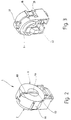
- Fig. 1 shows an explosion-proof lamp holder 1 in a perspective exploded view.
- the lamp holder 1 essentially comprises a housing 2, a contact means carrier 3 rotatably mounted in the housing 2, a one-piece, spring-elastic contact means 4 seated in the contact means carrier 3, and two covers 5 and 6.
- the housing 2 consists of an approximately cup-shaped part 7, which has an approximately cylindrical collar 8 and a base 9, the collar ending at a flat edge 10 parallel to the base.
- a foot section 11 is integrally formed on the cup-shaped part, which is approximately cuboid in shape and has locking lugs 12 with which the foot part 11 is to be anchored in a lamp housing.
- the two sections 14 and 16 are coaxial with each other.
- the collar 8 is provided with two grooves 17 and 18 with a rectangular cross section, the longitudinal extent of which extends parallel to the longitudinal axis of the cylindrical interior sections 14 and 16. At its end adjacent to the rear or the bottom, each of the two grooves 17 and 18 contains a step-shaped recess 21 in its bottom 19.
- the two grooves 17 and 18 lie diametrically opposite one another with respect to the longitudinal axis of the cylindrical interior sections 14 and 16 and are at the same distance from the foot part 11.
- the wall of the interior section 14 carries two cams 23 who are about Raising two straight inclined surfaces 23 from the inner wall and passing over a sharp-edged apex parallel to the longitudinal axis into a trough-shaped surface 24, which serves as a locking device in a form to be explained further below.
- the axis of curvature of the trough 24 is also parallel to the longitudinal axis.
- the collar 8 in the region of the interior section 14 contains a slot 27 which is open towards the edge 10 and is opposite the foot part 11, i.e. the slot 27 is located centrally between the two trough-shaped surfaces 24.
- the contact medium carrier 3 is an essentially cylindrical molded part made of plastic with a cylindrical outer surface 28 and a chamber 29 contained therein, which opens in the same direction as the interior 13.
- the chamber 29 has a series of shoulder or guide surfaces 31, 32, 33 and 34, which serve to guide and contact the contact means 4.
- the two surfaces 31 and 32 run parallel and at a distance from one another, while the surfaces 33 and 34 form the rear wall of the chamber 29, through which an opening 35 with a rectangular cross section leads to the rear.
- the cylindrical body 28 is provided with rectangular slots 36 and 37, which extend to the height of the two rear surfaces 33 and 34. Furthermore, the cylindrical body 28 contains a further slot 38 lying between the two slots 36 and 37, which has the same function as the slot 27 in the housing 2.
- a profiled extension 39 provided with interior spaces, into which a contact spring 41 is to be inserted, which is used to connect external wiring.
- a cap 42 On the rear extension 39 fits a cap 42 which, with the aid of a plurality of locking lugs 43, which can engage in corresponding locking recesses in the cylindrical body 28 which cannot be seen in the figure, and which completely cover the rear extension 39 together with the contact spring 41 located therein. Only an opening 44 in the bottom of the cap 42 allows the insertion of a wire coming from the outside.
- the contact means 4 consists of two integrally connected contact members 45 and 46, which are mirror images of one another, and two ring-shaped or ⁇ -shaped springs 47, of which only one can be seen for reasons of illustration.
- the entire contact means 4 is a stamped and bent part and consists of a spring-hard and spring-elastic material, for example spring bronze.
- the stamped and bent part is shaped in such a way that the previously mentioned two ring-shaped or omega-shaped springs 47 are formed by stamping and bending, from the free ends of which two arms 48, which lie in the same plane, lead away tangentially.
- the plate-shaped arms 48 merge at their free ends into mutually parallel and spaced-apart surfaces 49 which run at right angles to the plane defined by the arms 48 and point away from the two omega-shaped springs 47.
- the surfaces 49 are also angled at their free ends and merge in one piece into two contact blades 52 and 53, which partially overlap one another.
- the two contact blades 52 and 53 run in front of one another with little play, similar to curtains, and have the shape of flat, approximately rectangular plates, which also run parallel to the two arms 48, but spaced from them.
- each of the two contact blades 52, 53 there is a U-shaped one Contain slot 54, namely the two U-shaped slots 54 are aligned, ie they penetrate the edge of the associated contact blade 52, 53 on the same side.
- omega-shaped springs 47 On the apex of the omega-shaped springs 47, which is distant from the two contact blades 52, 53, two two-armed leaf springs 55 and 56 are formed, which extend essentially parallel to the contact blades 52, 53, but at a distance from them.
- the cover 5 is provided, which essentially has the shape of a flat disk, from which a cylindrical extension 59 protrudes coaxially on a front side 58 facing the viewer.
- a plurality of locking hooks 61 are formed on the disc 58, which cooperate with corresponding ribs 62 of the contact medium carrier 3 in order to fix the cover 5 there.
- Pins 62 which are molded onto the back of the cover 5, engage in corresponding groove areas of the contact-medium carrier 3 and ensure that they are secured against rotation.
- the cover 6 also has a disk-shaped shape, two latching hooks 64 being formed on two diametrically opposite sides, which should engage behind the latching shoulder 21 with their latching lugs 65.
- the width of the locking lugs 64, measured in the circumferential direction of the cover 6, corresponds to the width of the two grooves 17 and 18.
- a collar 66 extends along the upper half of the cover 6, while the lower region of the cover 6 is formed at 67 without this collar 66.
- the socket shown in FIG. 1 is assembled in such a way that the one-piece contact means 4 is first inserted into the chamber 29 of the contact means carrier 4.
- the two omega-shaped springs 47 sit in the opening 35, while the rectangular contact blades 52 and 53 are guided in height between the two mutually parallel surfaces 31 and 32.
- the two cam follower members 51 protrude laterally or radially through the two slots 36 and 37 and their outer surfaces protrude beyond the outer peripheral surface of the cylindrical body 28.
- the contact means 4 was used in such a way that the U-shaped slot 54 opens to the surface 32 which is penetrated by the slot 38.
- the cover 5 is snapped on, the hooks 61 hooking behind the ribs 62.
- the contact spring 41 is then threaded onto the contact tab 57 and the cap becomes from the rear 42 latches with the contact medium carrier by the hooks 43 latching into corresponding recesses in the contact medium carrier 3 which cannot be seen in the drawing.
- corresponding slots 69 are provided in the latching hooks 43, through which the leaf springs 55 and 56 protrude outwards.
- the contact medium carrier 3 After the contact medium carrier 3 has been completely equipped and assembled, it is inserted with the cap 42 ahead into the interior 13 of the housing 2, the cap 42 projecting rearward through a corresponding opening 71 in the base 9. In this position, the leaf springs 55 and 56 are supported on an area of the base 9 surrounding the opening 71 and tension the contact carrier 3 together with the structural units attached to it in the forward direction, i.e. based on Fig. 1, to the right before. Finally, the cover 6 is put on and locked. In this assembled position, the cylindrical projection 59 is located in the bore 69 and, moreover, the slot 63 is aligned with the slot 68. Its section in the collar 66, however, is aligned with the slot 38 and with the slot 27 in the housing 2.
- the cam follower members 51 are also located in the associated troughs 24, the axis of curvature of which runs parallel to the longitudinal axis of the contact carrier 3.
- the distance between the two troughs 24 is such that in In cooperation with the cam follower 51, the two contact blades 52 and 53 are shifted against each other until their U-shaped slots 54 are aligned with one another.
- the position of the contact means 4 is illustrated with the omission of the covers 5 and 6 and the contact means carrier 3.
- the two U-shaped slots 54 are congruent and aligned with the open end of the slot 38.
- the width of the slot 68 as well as the width of the slot 63 is slightly larger than the diameter of the two lamp pins 25 corresponds.
- the diameter of the opening 69 is somewhat larger than the spacing of the two lamp pins 25 from one another, measured over all.
- the width of the U-shaped slots 54 is greater than the width of the slots 63 and 68, and their width is in turn greater than the diameter of the lamp pins 25, so that no force is opposed to the insertion movement.
- the contact blades 52, 53 are in the shadow of the cover 5 and 6, so that initially no contact can occur between the lamp pins and the contact means 4.
- the cam followers 51 are released from the cams 22, so that the contact blades 52 and 53 can move freely against one another due to the spring force of the two omega-shaped ring springs 47 until they meet the edges of the U-shaped slots 54 on the Lamp pins 25 abut. In this position, the detection of the lamp pins 25 is in the form of pliers or scissors.
- the diameter of the interior section 44 is selected beyond the two cams 22 so that the cam follower 51 can not come into contact with the wall. It is thereby achieved that the spring force of the omega-shaped springs 47 can fully take effect on the lamp pins 25.
- the rotated position is illustrated in FIG. 5, with the lamp pins 25 being omitted.
- the removal of the lamp 26 takes place in the opposite direction, in that the lamp 26 first around its Longitudinal axis is rotated until the slot 63 is aligned with the slot 68. In this position, the cam followers 51 and the inclined surfaces 23 run up and get into the troughs 24. The cams 22, together with the cam followers 51, press the contact members 46 against one another again, as a result of which the two slots 54 are brought into congruence again. The fluorescent lamp 26 can now be pulled out of the socket 1 in question without any force.
- inserting or removing the fluorescent lamp 26 from the socket 1 does not require the lamp pins 25 to overcome the contact force. Rather, the insertion takes place without any contact force and the contact force is only released after the lamp pins 25 are in the right place in the socket 2.
- the contact force is released by rotating the fluorescent lamp 1 about its longitudinal axis, as is also the case with conventional, non-explosion-proof lamps.
- This rotary movement on the one hand loads the lamp pins 25 only slightly and on the other hand the construction shown of the lamp holder 1 ensures that as soon as the apex between the trough 24 and the inclined surface 23 is overcome, the contact means carrier 4 is automatically rotated into a position in which the two contact blades 52 and 53 apply full force to the lamp pins 25.
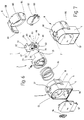
- FIGS. 5 and 6 Another embodiment of the lamp holder according to the invention is shown in FIGS. 5 and 6.
- the contact means 4 is formed from two mutually movable jaws 81 and 82 which are prestressed into the closed position by means of a compression spring 83. Since the rest of the handling and operation is the same as in the previous embodiment, the functionally corresponding parts are provided with the same reference numerals and the following description is essentially limited to the design differences.
- the contact means carrier 3 which in turn has a chamber 29 for receiving the contact means 4, is biased towards the lamp with the aid of a helical compression spring 84.
- the compression spring 84 is arranged between the back of the contact medium carrier 3 and the bottom 9 of the interior 13.
- the contact means 4 consists of, as mentioned, two mutually movable jaws 81 and 82, both of which are approximately U-shaped in the side view, the cam follower 51 being arranged on one leg 85, while another leg 86, which has a base piece 87 is connected to the leg 85, which represents the actual contact surface.
- the other jaw 81 is also U-shaped when viewed from the side, but is arranged upside down, as is the case this shows the figure.
- a base section 87 of the jaw 81 there is a slot 88 leading in from the side, one edge 89 of which cooperates with the leg 86.
- One leg 91 of the jaw 81 is elongated and, as shown, extends through a rectangular opening 92 in the base portion 87.
- the compression spring 83 is supported on the one hand on the leg 86 and on the other hand on a further leg 93 which belongs to the jaws 81.
- the leg 93 carries the other cam follower member 51 on the invisible side. Because of this arrangement, the leg 86 and the slot edge 89 are pressed against one another by the compression spring 83.
- the laterally drawn out cover 5 is locked with the locking lugs 61 within the cylindrical contact means carrier 3, in such a way that the slot 63 runs parallel to the slot edge 89.
- the electrical connection to external wiring takes place with the aid of a piece of stranded wire 94 which is fastened on the one hand to the leg 91 and on the other hand is connected to a screw terminal 95 which is located in a chamber 96 on the rear of the housing 2.
- the chamber 96 is closed by a rear cover 97 in the assembled state.
- front cover 6 is designed as mentioned above.
- the lamp holder according to FIG. 6 is assembled in such a way that the jaw 82 is threaded onto the leg extension 91 from the rear until the jaw 86 comes into contact with the slot edge 89.
- the compression spring 83 is then inserted and the strand 94 is welded to the leg 91.
- the contact means 4 obtained in this way is inserted into the chamber 29 of the contact means carrier 3, the front side of which is closed with the cover 5.
- the pre-assembled assembly inserted with the interposition of the helical compression spring 84 in the housing 2 and held by means of the cover 6 snapped onto the housing 2.
- the cover 6 is in turn, as in the aforementioned example, slightly displaceable in the longitudinal direction of the latching hooks 64 relative to the housing 2.
- the rear cover 97 is snapped on, with which the lamp holder is fully assembled. Their assembled state is shown in Fig. 7.
- the handling is, as already explained, i.e. in a position of the contact carrier, in which the slot 63 is aligned with the slot 68, the jaws 22, which cooperate with the two cam followers 51, move the jaws against the action of the helical compression spring 83 and they limit a slot which is parallel to the Slot 63 runs and has a larger width than this.
- the insertion of the lamp pins 25 is possible.
- the fluorescent lamp 26 is rotated about its longitudinal axis, which results in the contact carrier 3 rotating, since the cover 5 is connected to the latter in a rotationally fixed manner. The rotational movement of the fluorescent lamp 26 is transmitted by the lamp pins 25.
Landscapes
- Connecting Device With Holders (AREA)
- Arrangement Of Elements, Cooling, Sealing, Or The Like Of Lighting Devices (AREA)
- Non-Portable Lighting Devices Or Systems Thereof (AREA)
- Fastening Of Light Sources Or Lamp Holders (AREA)
Applications Claiming Priority (2)
| Application Number | Priority Date | Filing Date | Title |
|---|---|---|---|
| DE19522719A DE19522719C1 (de) | 1995-06-22 | 1995-06-22 | Explosionsgeschützte Lampenfassung mit wahlweise zu öffnenden und zu schließenden Kontaktmitteln |
| DE19522719 | 1995-06-22 |
Publications (3)
| Publication Number | Publication Date |
|---|---|
| EP0762563A2 true EP0762563A2 (fr) | 1997-03-12 |
| EP0762563A3 EP0762563A3 (fr) | 1997-07-09 |
| EP0762563B1 EP0762563B1 (fr) | 2002-10-16 |
Family
ID=7765015
Family Applications (1)
| Application Number | Title | Priority Date | Filing Date |
|---|---|---|---|
| EP96107321A Expired - Lifetime EP0762563B1 (fr) | 1995-06-22 | 1996-05-09 | Douille de lampe anti-déflagrante avec, facultativement, des contacts à ouverture ou fermeture |
Country Status (3)
| Country | Link |
|---|---|
| EP (1) | EP0762563B1 (fr) |
| AT (1) | ATE226367T1 (fr) |
| DE (2) | DE19522719C1 (fr) |
Families Citing this family (3)
| Publication number | Priority date | Publication date | Assignee | Title |
|---|---|---|---|---|
| DE19714860C2 (de) * | 1997-04-10 | 1999-02-25 | Broekelmann Jaeger & Busse | Lampenfassung mit Schutzeinrichtung gegen Eindringen von Partikeln |
| EP1965127B1 (fr) * | 2007-02-28 | 2014-08-13 | Siteco Beleuchtungstechnik GmbH | Dispositif de protection pour une lampe |
| CN102777866A (zh) * | 2012-07-20 | 2012-11-14 | 深圳市易事达电子有限公司 | 一种灯管堵头及led日光灯 |
Citations (4)
| Publication number | Priority date | Publication date | Assignee | Title |
|---|---|---|---|---|
| EP0304812A2 (fr) * | 1987-08-25 | 1989-03-01 | ABB CEAG Licht- und Stromversorgungstechnik GmbH | Lampe antidéflagrante |
| DE8815752U1 (fr) * | 1987-12-24 | 1989-04-06 | Adolf Schuch Kg, Lichttechnische Spezialfabrik, 6520 Worms, De | |
| EP0344628A1 (fr) * | 1988-06-03 | 1989-12-06 | ABB CEAG Licht- und Stromversorgungstechnik GmbH | Douille antidéflagrante pour 2 broches-tubes fluorescents |
| DE3943065C1 (en) * | 1989-12-28 | 1991-05-02 | R. Stahl Schaltgeraete Gmbh, 7118 Kuenzelsau, De | Explosion-protected lamp holder or socket for two-pin base lamp - has two borings in housing arranged in parallel to axis of rotation |
Family Cites Families (1)
| Publication number | Priority date | Publication date | Assignee | Title |
|---|---|---|---|---|
| DE3621960A1 (de) * | 1986-07-01 | 1988-01-14 | Wagner Robert | Explosionsgeschuetzte fassung und leuchte fuer zweistiftsockel-leuchtstofflampen |
-
1995
- 1995-06-22 DE DE19522719A patent/DE19522719C1/de not_active Expired - Fee Related
-
1996
- 1996-05-09 AT AT96107321T patent/ATE226367T1/de not_active IP Right Cessation
- 1996-05-09 EP EP96107321A patent/EP0762563B1/fr not_active Expired - Lifetime
- 1996-05-09 DE DE59609796T patent/DE59609796D1/de not_active Expired - Lifetime
Patent Citations (4)
| Publication number | Priority date | Publication date | Assignee | Title |
|---|---|---|---|---|
| EP0304812A2 (fr) * | 1987-08-25 | 1989-03-01 | ABB CEAG Licht- und Stromversorgungstechnik GmbH | Lampe antidéflagrante |
| DE8815752U1 (fr) * | 1987-12-24 | 1989-04-06 | Adolf Schuch Kg, Lichttechnische Spezialfabrik, 6520 Worms, De | |
| EP0344628A1 (fr) * | 1988-06-03 | 1989-12-06 | ABB CEAG Licht- und Stromversorgungstechnik GmbH | Douille antidéflagrante pour 2 broches-tubes fluorescents |
| DE3943065C1 (en) * | 1989-12-28 | 1991-05-02 | R. Stahl Schaltgeraete Gmbh, 7118 Kuenzelsau, De | Explosion-protected lamp holder or socket for two-pin base lamp - has two borings in housing arranged in parallel to axis of rotation |
Also Published As
| Publication number | Publication date |
|---|---|
| EP0762563A3 (fr) | 1997-07-09 |
| DE19522719C1 (de) | 1997-01-30 |
| DE59609796D1 (de) | 2002-11-21 |
| EP0762563B1 (fr) | 2002-10-16 |
| ATE226367T1 (de) | 2002-11-15 |
Similar Documents
| Publication | Publication Date | Title |
|---|---|---|
| DE102012110895B4 (de) | Anschlussklemme | |
| EP0212330B1 (fr) | Borne de jonction ou serre-fil pour appareils électriques | |
| EP2395605B1 (fr) | Elément de serrage de ressort et bornier | |
| EP3477775A2 (fr) | Borne de connexion de conducteur et insert de contact | |
| DE4312776C2 (de) | Fassung für elektrische Betriebsmittel | |
| EP3961821B1 (fr) | Dispositif de connexion doté d'un connecteur enfichable et d'un connecteur enfichable complémentaire | |
| DE2425462C2 (de) | Elektrischer Buchsenkontakt | |
| DE19603135C1 (de) | Selbstjustierender Stößelschalter | |
| DE102005005917B4 (de) | Anschlussklemme für einen isolierten elektrischen Leiter | |
| DE19522719C1 (de) | Explosionsgeschützte Lampenfassung mit wahlweise zu öffnenden und zu schließenden Kontaktmitteln | |
| WO1986007199A1 (fr) | Borne de connexion | |
| DE102019114553A1 (de) | Dehnverbinder für eine Schleifleitung und Schleifleitung | |
| DE10117570B4 (de) | Elektrischer Kontakt sowie Lampenfassung und Anschluss- oder Verbindungsklemme mit mindestens einem solchen Kontakt | |
| DE3620105C1 (en) | Electrical contact switch | |
| DE2706988A1 (de) | Schraubenlose anschlussklemme zur stromuebertragung von elektrischen leitern | |
| EP0892997B1 (fr) | Connecteur a fiches pour cables | |
| DE102013014202B4 (de) | Steckverbindersystem | |
| DE2439249A1 (de) | Gluehlampe und sockel | |
| DE10218507C1 (de) | Anschluss- und/oder Verbindungsklemme | |
| EP0282624A2 (fr) | Porte-fusible électrique protégé contre l'attouchement | |
| CH653181A5 (en) | Electrical connecting element | |
| DE3445592A1 (de) | Klemme zum schraublosen anschluss von anschlussdraehten bei elektrischen installationsgeraeten | |
| EP1467448B1 (fr) | Adaptateur de connecteur, notament pour connexion de lampes | |
| DE2905377C3 (de) | Elektrischer Schalter | |
| DE102018100787B4 (de) | Seilhalter zum Befestigen eines Objektes an einem Seil |
Legal Events
| Date | Code | Title | Description |
|---|---|---|---|
| PUAI | Public reference made under article 153(3) epc to a published international application that has entered the european phase |
Free format text: ORIGINAL CODE: 0009012 |
|
| AK | Designated contracting states |
Kind code of ref document: A2 Designated state(s): AT BE CH DE DK ES FI FR GB GR IE IT LI LU NL PT SE |
|
| AX | Request for extension of the european patent |
Free format text: LT PAYMENT 960605;LV PAYMENT 960605;SI PAYMENT 960605 |
|
| PUAL | Search report despatched |
Free format text: ORIGINAL CODE: 0009013 |
|
| AK | Designated contracting states |
Kind code of ref document: A3 Designated state(s): AT BE CH DE DK ES FI FR GB GR IE IT LI LU NL PT SE |
|
| AX | Request for extension of the european patent |
Free format text: LT PAYMENT 960605;LV PAYMENT 960605;SI PAYMENT 960605 |
|
| 17P | Request for examination filed |
Effective date: 19970819 |
|
| 17Q | First examination report despatched |
Effective date: 19990802 |
|
| GRAG | Despatch of communication of intention to grant |
Free format text: ORIGINAL CODE: EPIDOS AGRA |
|
| GRAG | Despatch of communication of intention to grant |
Free format text: ORIGINAL CODE: EPIDOS AGRA |
|
| GRAH | Despatch of communication of intention to grant a patent |
Free format text: ORIGINAL CODE: EPIDOS IGRA |
|
| GRAH | Despatch of communication of intention to grant a patent |
Free format text: ORIGINAL CODE: EPIDOS IGRA |
|
| GRAA | (expected) grant |
Free format text: ORIGINAL CODE: 0009210 |
|
| AK | Designated contracting states |
Kind code of ref document: B1 Designated state(s): AT BE CH DE DK ES FI FR GB GR IE IT LI LU NL PT SE |
|
| AX | Request for extension of the european patent |
Free format text: LT PAYMENT 19960605;LV PAYMENT 19960605;SI PAYMENT 19960605 |
|
| PG25 | Lapsed in a contracting state [announced via postgrant information from national office to epo] |
Ref country code: NL Free format text: LAPSE BECAUSE OF FAILURE TO SUBMIT A TRANSLATION OF THE DESCRIPTION OR TO PAY THE FEE WITHIN THE PRESCRIBED TIME-LIMIT Effective date: 20021016 Ref country code: IT Free format text: LAPSE BECAUSE OF FAILURE TO SUBMIT A TRANSLATION OF THE DESCRIPTION OR TO PAY THE FEE WITHIN THE PRE;WARNING: LAPSES OF ITALIAN PATENTS WITH EFFECTIVE DATE BEFORE 2007 MAY HAVE OCCURRED AT ANY TIME BEFORE 2007. THE CORRECT EFFECTIVE DATE MAY BE DIFFERENT FROM THE ONE RECORDED.SCRIBED TIME-LIMIT Effective date: 20021016 Ref country code: IE Free format text: LAPSE BECAUSE OF FAILURE TO SUBMIT A TRANSLATION OF THE DESCRIPTION OR TO PAY THE FEE WITHIN THE PRESCRIBED TIME-LIMIT Effective date: 20021016 Ref country code: GR Free format text: LAPSE BECAUSE OF FAILURE TO SUBMIT A TRANSLATION OF THE DESCRIPTION OR TO PAY THE FEE WITHIN THE PRESCRIBED TIME-LIMIT Effective date: 20021016 Ref country code: FI Free format text: LAPSE BECAUSE OF FAILURE TO SUBMIT A TRANSLATION OF THE DESCRIPTION OR TO PAY THE FEE WITHIN THE PRESCRIBED TIME-LIMIT Effective date: 20021016 |
|
| REF | Corresponds to: |
Ref document number: 226367 Country of ref document: AT Date of ref document: 20021115 Kind code of ref document: T |
|
| REG | Reference to a national code |
Ref country code: GB Ref legal event code: FG4D Free format text: NOT ENGLISH |
|
| REG | Reference to a national code |
Ref country code: CH Ref legal event code: EP |
|
| REG | Reference to a national code |
Ref country code: IE Ref legal event code: FG4D Free format text: GERMAN |
|
| REF | Corresponds to: |
Ref document number: 59609796 Country of ref document: DE Date of ref document: 20021121 |
|
| PG25 | Lapsed in a contracting state [announced via postgrant information from national office to epo] |
Ref country code: SE Free format text: LAPSE BECAUSE OF FAILURE TO SUBMIT A TRANSLATION OF THE DESCRIPTION OR TO PAY THE FEE WITHIN THE PRESCRIBED TIME-LIMIT Effective date: 20030116 Ref country code: PT Free format text: LAPSE BECAUSE OF FAILURE TO SUBMIT A TRANSLATION OF THE DESCRIPTION OR TO PAY THE FEE WITHIN THE PRESCRIBED TIME-LIMIT Effective date: 20030116 Ref country code: DK Free format text: LAPSE BECAUSE OF FAILURE TO SUBMIT A TRANSLATION OF THE DESCRIPTION OR TO PAY THE FEE WITHIN THE PRESCRIBED TIME-LIMIT Effective date: 20030116 |
|
| GBT | Gb: translation of ep patent filed (gb section 77(6)(a)/1977) |
Effective date: 20030131 |
|
| LTIE | Lt: invalidation of european patent or patent extension |
Effective date: 20021016 |
|
| NLV1 | Nl: lapsed or annulled due to failure to fulfill the requirements of art. 29p and 29m of the patents act | ||
| PG25 | Lapsed in a contracting state [announced via postgrant information from national office to epo] |
Ref country code: ES Free format text: LAPSE BECAUSE OF FAILURE TO SUBMIT A TRANSLATION OF THE DESCRIPTION OR TO PAY THE FEE WITHIN THE PRESCRIBED TIME-LIMIT Effective date: 20030429 |
|
| PG25 | Lapsed in a contracting state [announced via postgrant information from national office to epo] |
Ref country code: LU Free format text: LAPSE BECAUSE OF NON-PAYMENT OF DUE FEES Effective date: 20030509 Ref country code: AT Free format text: LAPSE BECAUSE OF NON-PAYMENT OF DUE FEES Effective date: 20030509 |
|
| ET | Fr: translation filed | ||
| PG25 | Lapsed in a contracting state [announced via postgrant information from national office to epo] |
Ref country code: LI Free format text: LAPSE BECAUSE OF NON-PAYMENT OF DUE FEES Effective date: 20030531 Ref country code: CH Free format text: LAPSE BECAUSE OF NON-PAYMENT OF DUE FEES Effective date: 20030531 Ref country code: BE Free format text: LAPSE BECAUSE OF NON-PAYMENT OF DUE FEES Effective date: 20030531 |
|
| REG | Reference to a national code |
Ref country code: IE Ref legal event code: FD4D Ref document number: 0762563E Country of ref document: IE |
|
| PLBE | No opposition filed within time limit |
Free format text: ORIGINAL CODE: 0009261 |
|
| STAA | Information on the status of an ep patent application or granted ep patent |
Free format text: STATUS: NO OPPOSITION FILED WITHIN TIME LIMIT |
|
| 26N | No opposition filed |
Effective date: 20030717 |
|
| BERE | Be: lapsed |
Owner name: R. *STAHL SCHALTGERATE G.M.B.H. Effective date: 20030531 |
|
| REG | Reference to a national code |
Ref country code: CH Ref legal event code: PL |
|
| PGFP | Annual fee paid to national office [announced via postgrant information from national office to epo] |
Ref country code: GB Payment date: 20140521 Year of fee payment: 19 |
|
| PGFP | Annual fee paid to national office [announced via postgrant information from national office to epo] |
Ref country code: DE Payment date: 20140429 Year of fee payment: 19 Ref country code: FR Payment date: 20140527 Year of fee payment: 19 |
|
| REG | Reference to a national code |
Ref country code: DE Ref legal event code: R119 Ref document number: 59609796 Country of ref document: DE |
|
| GBPC | Gb: european patent ceased through non-payment of renewal fee |
Effective date: 20150509 |
|
| REG | Reference to a national code |
Ref country code: FR Ref legal event code: ST Effective date: 20160129 |
|
| PG25 | Lapsed in a contracting state [announced via postgrant information from national office to epo] |
Ref country code: GB Free format text: LAPSE BECAUSE OF NON-PAYMENT OF DUE FEES Effective date: 20150509 Ref country code: DE Free format text: LAPSE BECAUSE OF NON-PAYMENT OF DUE FEES Effective date: 20151201 |
|
| PG25 | Lapsed in a contracting state [announced via postgrant information from national office to epo] |
Ref country code: FR Free format text: LAPSE BECAUSE OF NON-PAYMENT OF DUE FEES Effective date: 20150601 |