EP0762563A2 - Explosion-proof lamp holder with selectively opening or closing of contact means - Google Patents
Explosion-proof lamp holder with selectively opening or closing of contact means Download PDFInfo
- Publication number
- EP0762563A2 EP0762563A2 EP96107321A EP96107321A EP0762563A2 EP 0762563 A2 EP0762563 A2 EP 0762563A2 EP 96107321 A EP96107321 A EP 96107321A EP 96107321 A EP96107321 A EP 96107321A EP 0762563 A2 EP0762563 A2 EP 0762563A2
- Authority
- EP
- European Patent Office
- Prior art keywords
- lamp
- contact
- lamp holder
- holder according
- opening
- Prior art date
- Legal status (The legal status is an assumption and is not a legal conclusion. Google has not performed a legal analysis and makes no representation as to the accuracy of the status listed.)
- Granted
Links
Images


Classifications
-
- H—ELECTRICITY
- H01—ELECTRIC ELEMENTS
- H01R—ELECTRICALLY-CONDUCTIVE CONNECTIONS; STRUCTURAL ASSOCIATIONS OF A PLURALITY OF MUTUALLY-INSULATED ELECTRICAL CONNECTING ELEMENTS; COUPLING DEVICES; CURRENT COLLECTORS
- H01R33/00—Coupling devices specially adapted for supporting apparatus and having one part acting as a holder providing support and electrical connection via a counterpart which is structurally associated with the apparatus, e.g. lamp holders; Separate parts thereof
- H01R33/945—Holders with built-in electrical component
- H01R33/96—Holders with built-in electrical component with switch operated by engagement or disengagement of coupling
-
- H—ELECTRICITY
- H01—ELECTRIC ELEMENTS
- H01R—ELECTRICALLY-CONDUCTIVE CONNECTIONS; STRUCTURAL ASSOCIATIONS OF A PLURALITY OF MUTUALLY-INSULATED ELECTRICAL CONNECTING ELEMENTS; COUPLING DEVICES; CURRENT COLLECTORS
- H01R33/00—Coupling devices specially adapted for supporting apparatus and having one part acting as a holder providing support and electrical connection via a counterpart which is structurally associated with the apparatus, e.g. lamp holders; Separate parts thereof
- H01R33/05—Two-pole devices
- H01R33/06—Two-pole devices with two current-carrying pins, blades or analogous contacts, having their axes parallel to each other
- H01R33/08—Two-pole devices with two current-carrying pins, blades or analogous contacts, having their axes parallel to each other for supporting tubular fluorescent lamp
Definitions
- Lamp sockets for fluorescent lamps can only be used in potentially explosive areas outside of flameproof enclosures if the contact devices that establish the contacts between the lamp socket and the lamp pins meet special requirements. For example, vibrations must under no circumstances result in the contact between the contact devices of the socket and the lamp pins being lost for a short time, since this can cause sparks which ignite an ignitable mixture.
- DE-A-39 43 065 describes a lamp holder in which the sockets contain so-called lamella contacts which meet the above-mentioned requirements.
- the bushings are seated in a support which is rotatably mounted in the housing of the socket and which simultaneously moves axially when rotated.
- the carrier is provided on its outside with a steep thread which fits into a corresponding steep thread of the socket housing.
- DE-A 36 21 960 describes an explosion-proof luminaire which contains resiliently displaceable sockets in its housing.
- the sockets there are contacts made of leaf springs, which are opened with the help of a Bowden cable mechanism.
- the Bowden cable mechanism is connected to a locking lever for the lamp housing and transfers the contact means into the open position as soon as the cover of the housing is unlocked.
- this construction there is no contact force when the lamp is inserted, but this advantage is bought with a high manufacturing outlay in the manufacture of the lamp.
- the use of the contact means which can optionally be opened and closed makes it possible, on the one hand, to use a very high contact force and, on the other hand, to use the lamp with the lamp pins without any particular force being opposed to the insertion movement of the lamp pins.
- Closing the contact means in order to establish the perfect electrical connection to the lamp pins does not require any additional measures, such as Bowden cables and the like, that are present outside the lamp holder, but a corresponding movement of the lamp is sufficient, for example as is the case with the usual non-explosion-proof lamps is used to.
- the contacts that can be optionally opened and closed in the solution according to the invention enable a considerably simpler construction of the other parts of the lamp holder compared to the prior art, and the contact means themselves can also be simple stamped and bent parts, for example.
- a very good contact with a high contact force is obtained if the contact members of the contact means grip the lamp pins in the manner of pliers or scissors.
- the opening is an elongated opening and it has such a dimension that in the case of two-pin lamps, both pins fit in, which are then automatically electrically connected to one another, as is required when operating in potentially explosive areas .
- the contact members can have contact blades that either move in a common plane or in succession in two different planes.
- the last embodiment has the advantage that in a one-piece embodiment of the two contact members the desired contact force is generated by appropriate bias, which on the other hand can be canceled to insert the lamp by moving both contact members from the side towards each other, whereby the opening expands accordingly. In conjunction with the cam means, this results in a particularly reliable contact, since the desired contact force is achieved immediately after the lamp in the socket is rotated simply by releasing the contact members.
- An undesirable gap between the lamp holder and the relevant front end of the lamp can also be prevented if a correspondingly movable cover is seated on the housing of the holder.
- the latter can also advantageously be movable together with the contact means carrier, which ensures very good guidance.
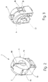
- Fig. 1 shows an explosion-proof lamp holder 1 in a perspective exploded view.
- the lamp holder 1 essentially comprises a housing 2, a contact means carrier 3 rotatably mounted in the housing 2, a one-piece, spring-elastic contact means 4 seated in the contact means carrier 3, and two covers 5 and 6.
- the housing 2 consists of an approximately cup-shaped part 7, which has an approximately cylindrical collar 8 and a base 9, the collar ending at a flat edge 10 parallel to the base.
- a foot section 11 is integrally formed on the cup-shaped part, which is approximately cuboid in shape and has locking lugs 12 with which the foot part 11 is to be anchored in a lamp housing.
- the two sections 14 and 16 are coaxial with each other.
- the collar 8 is provided with two grooves 17 and 18 with a rectangular cross section, the longitudinal extent of which extends parallel to the longitudinal axis of the cylindrical interior sections 14 and 16. At its end adjacent to the rear or the bottom, each of the two grooves 17 and 18 contains a step-shaped recess 21 in its bottom 19.
- the two grooves 17 and 18 lie diametrically opposite one another with respect to the longitudinal axis of the cylindrical interior sections 14 and 16 and are at the same distance from the foot part 11.
- the wall of the interior section 14 carries two cams 23 who are about Raising two straight inclined surfaces 23 from the inner wall and passing over a sharp-edged apex parallel to the longitudinal axis into a trough-shaped surface 24, which serves as a locking device in a form to be explained further below.
- the axis of curvature of the trough 24 is also parallel to the longitudinal axis.
- the collar 8 in the region of the interior section 14 contains a slot 27 which is open towards the edge 10 and is opposite the foot part 11, i.e. the slot 27 is located centrally between the two trough-shaped surfaces 24.
- the contact medium carrier 3 is an essentially cylindrical molded part made of plastic with a cylindrical outer surface 28 and a chamber 29 contained therein, which opens in the same direction as the interior 13.
- the chamber 29 has a series of shoulder or guide surfaces 31, 32, 33 and 34, which serve to guide and contact the contact means 4.
- the two surfaces 31 and 32 run parallel and at a distance from one another, while the surfaces 33 and 34 form the rear wall of the chamber 29, through which an opening 35 with a rectangular cross section leads to the rear.
- the cylindrical body 28 is provided with rectangular slots 36 and 37, which extend to the height of the two rear surfaces 33 and 34. Furthermore, the cylindrical body 28 contains a further slot 38 lying between the two slots 36 and 37, which has the same function as the slot 27 in the housing 2.
- a profiled extension 39 provided with interior spaces, into which a contact spring 41 is to be inserted, which is used to connect external wiring.
- a cap 42 On the rear extension 39 fits a cap 42 which, with the aid of a plurality of locking lugs 43, which can engage in corresponding locking recesses in the cylindrical body 28 which cannot be seen in the figure, and which completely cover the rear extension 39 together with the contact spring 41 located therein. Only an opening 44 in the bottom of the cap 42 allows the insertion of a wire coming from the outside.
- the contact means 4 consists of two integrally connected contact members 45 and 46, which are mirror images of one another, and two ring-shaped or ⁇ -shaped springs 47, of which only one can be seen for reasons of illustration.
- the entire contact means 4 is a stamped and bent part and consists of a spring-hard and spring-elastic material, for example spring bronze.
- the stamped and bent part is shaped in such a way that the previously mentioned two ring-shaped or omega-shaped springs 47 are formed by stamping and bending, from the free ends of which two arms 48, which lie in the same plane, lead away tangentially.
- the plate-shaped arms 48 merge at their free ends into mutually parallel and spaced-apart surfaces 49 which run at right angles to the plane defined by the arms 48 and point away from the two omega-shaped springs 47.
- the surfaces 49 are also angled at their free ends and merge in one piece into two contact blades 52 and 53, which partially overlap one another.
- the two contact blades 52 and 53 run in front of one another with little play, similar to curtains, and have the shape of flat, approximately rectangular plates, which also run parallel to the two arms 48, but spaced from them.
- each of the two contact blades 52, 53 there is a U-shaped one Contain slot 54, namely the two U-shaped slots 54 are aligned, ie they penetrate the edge of the associated contact blade 52, 53 on the same side.
- omega-shaped springs 47 On the apex of the omega-shaped springs 47, which is distant from the two contact blades 52, 53, two two-armed leaf springs 55 and 56 are formed, which extend essentially parallel to the contact blades 52, 53, but at a distance from them.
- the cover 5 is provided, which essentially has the shape of a flat disk, from which a cylindrical extension 59 protrudes coaxially on a front side 58 facing the viewer.
- a plurality of locking hooks 61 are formed on the disc 58, which cooperate with corresponding ribs 62 of the contact medium carrier 3 in order to fix the cover 5 there.
- Pins 62 which are molded onto the back of the cover 5, engage in corresponding groove areas of the contact-medium carrier 3 and ensure that they are secured against rotation.
- the cover 6 also has a disk-shaped shape, two latching hooks 64 being formed on two diametrically opposite sides, which should engage behind the latching shoulder 21 with their latching lugs 65.
- the width of the locking lugs 64, measured in the circumferential direction of the cover 6, corresponds to the width of the two grooves 17 and 18.
- a collar 66 extends along the upper half of the cover 6, while the lower region of the cover 6 is formed at 67 without this collar 66.
- the socket shown in FIG. 1 is assembled in such a way that the one-piece contact means 4 is first inserted into the chamber 29 of the contact means carrier 4.
- the two omega-shaped springs 47 sit in the opening 35, while the rectangular contact blades 52 and 53 are guided in height between the two mutually parallel surfaces 31 and 32.
- the two cam follower members 51 protrude laterally or radially through the two slots 36 and 37 and their outer surfaces protrude beyond the outer peripheral surface of the cylindrical body 28.
- the contact means 4 was used in such a way that the U-shaped slot 54 opens to the surface 32 which is penetrated by the slot 38.
- the cover 5 is snapped on, the hooks 61 hooking behind the ribs 62.
- the contact spring 41 is then threaded onto the contact tab 57 and the cap becomes from the rear 42 latches with the contact medium carrier by the hooks 43 latching into corresponding recesses in the contact medium carrier 3 which cannot be seen in the drawing.
- corresponding slots 69 are provided in the latching hooks 43, through which the leaf springs 55 and 56 protrude outwards.
- the contact medium carrier 3 After the contact medium carrier 3 has been completely equipped and assembled, it is inserted with the cap 42 ahead into the interior 13 of the housing 2, the cap 42 projecting rearward through a corresponding opening 71 in the base 9. In this position, the leaf springs 55 and 56 are supported on an area of the base 9 surrounding the opening 71 and tension the contact carrier 3 together with the structural units attached to it in the forward direction, i.e. based on Fig. 1, to the right before. Finally, the cover 6 is put on and locked. In this assembled position, the cylindrical projection 59 is located in the bore 69 and, moreover, the slot 63 is aligned with the slot 68. Its section in the collar 66, however, is aligned with the slot 38 and with the slot 27 in the housing 2.
- the cam follower members 51 are also located in the associated troughs 24, the axis of curvature of which runs parallel to the longitudinal axis of the contact carrier 3.
- the distance between the two troughs 24 is such that in In cooperation with the cam follower 51, the two contact blades 52 and 53 are shifted against each other until their U-shaped slots 54 are aligned with one another.
- the position of the contact means 4 is illustrated with the omission of the covers 5 and 6 and the contact means carrier 3.
- the two U-shaped slots 54 are congruent and aligned with the open end of the slot 38.
- the width of the slot 68 as well as the width of the slot 63 is slightly larger than the diameter of the two lamp pins 25 corresponds.
- the diameter of the opening 69 is somewhat larger than the spacing of the two lamp pins 25 from one another, measured over all.
- the width of the U-shaped slots 54 is greater than the width of the slots 63 and 68, and their width is in turn greater than the diameter of the lamp pins 25, so that no force is opposed to the insertion movement.
- the contact blades 52, 53 are in the shadow of the cover 5 and 6, so that initially no contact can occur between the lamp pins and the contact means 4.
- the cam followers 51 are released from the cams 22, so that the contact blades 52 and 53 can move freely against one another due to the spring force of the two omega-shaped ring springs 47 until they meet the edges of the U-shaped slots 54 on the Lamp pins 25 abut. In this position, the detection of the lamp pins 25 is in the form of pliers or scissors.
- the diameter of the interior section 44 is selected beyond the two cams 22 so that the cam follower 51 can not come into contact with the wall. It is thereby achieved that the spring force of the omega-shaped springs 47 can fully take effect on the lamp pins 25.
- the rotated position is illustrated in FIG. 5, with the lamp pins 25 being omitted.
- the removal of the lamp 26 takes place in the opposite direction, in that the lamp 26 first around its Longitudinal axis is rotated until the slot 63 is aligned with the slot 68. In this position, the cam followers 51 and the inclined surfaces 23 run up and get into the troughs 24. The cams 22, together with the cam followers 51, press the contact members 46 against one another again, as a result of which the two slots 54 are brought into congruence again. The fluorescent lamp 26 can now be pulled out of the socket 1 in question without any force.
- inserting or removing the fluorescent lamp 26 from the socket 1 does not require the lamp pins 25 to overcome the contact force. Rather, the insertion takes place without any contact force and the contact force is only released after the lamp pins 25 are in the right place in the socket 2.
- the contact force is released by rotating the fluorescent lamp 1 about its longitudinal axis, as is also the case with conventional, non-explosion-proof lamps.
- This rotary movement on the one hand loads the lamp pins 25 only slightly and on the other hand the construction shown of the lamp holder 1 ensures that as soon as the apex between the trough 24 and the inclined surface 23 is overcome, the contact means carrier 4 is automatically rotated into a position in which the two contact blades 52 and 53 apply full force to the lamp pins 25.
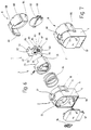
- FIGS. 5 and 6 Another embodiment of the lamp holder according to the invention is shown in FIGS. 5 and 6.
- the contact means 4 is formed from two mutually movable jaws 81 and 82 which are prestressed into the closed position by means of a compression spring 83. Since the rest of the handling and operation is the same as in the previous embodiment, the functionally corresponding parts are provided with the same reference numerals and the following description is essentially limited to the design differences.
- the contact means carrier 3 which in turn has a chamber 29 for receiving the contact means 4, is biased towards the lamp with the aid of a helical compression spring 84.
- the compression spring 84 is arranged between the back of the contact medium carrier 3 and the bottom 9 of the interior 13.
- the contact means 4 consists of, as mentioned, two mutually movable jaws 81 and 82, both of which are approximately U-shaped in the side view, the cam follower 51 being arranged on one leg 85, while another leg 86, which has a base piece 87 is connected to the leg 85, which represents the actual contact surface.
- the other jaw 81 is also U-shaped when viewed from the side, but is arranged upside down, as is the case this shows the figure.
- a base section 87 of the jaw 81 there is a slot 88 leading in from the side, one edge 89 of which cooperates with the leg 86.
- One leg 91 of the jaw 81 is elongated and, as shown, extends through a rectangular opening 92 in the base portion 87.
- the compression spring 83 is supported on the one hand on the leg 86 and on the other hand on a further leg 93 which belongs to the jaws 81.
- the leg 93 carries the other cam follower member 51 on the invisible side. Because of this arrangement, the leg 86 and the slot edge 89 are pressed against one another by the compression spring 83.
- the laterally drawn out cover 5 is locked with the locking lugs 61 within the cylindrical contact means carrier 3, in such a way that the slot 63 runs parallel to the slot edge 89.
- the electrical connection to external wiring takes place with the aid of a piece of stranded wire 94 which is fastened on the one hand to the leg 91 and on the other hand is connected to a screw terminal 95 which is located in a chamber 96 on the rear of the housing 2.
- the chamber 96 is closed by a rear cover 97 in the assembled state.
- front cover 6 is designed as mentioned above.
- the lamp holder according to FIG. 6 is assembled in such a way that the jaw 82 is threaded onto the leg extension 91 from the rear until the jaw 86 comes into contact with the slot edge 89.
- the compression spring 83 is then inserted and the strand 94 is welded to the leg 91.
- the contact means 4 obtained in this way is inserted into the chamber 29 of the contact means carrier 3, the front side of which is closed with the cover 5.
- the pre-assembled assembly inserted with the interposition of the helical compression spring 84 in the housing 2 and held by means of the cover 6 snapped onto the housing 2.
- the cover 6 is in turn, as in the aforementioned example, slightly displaceable in the longitudinal direction of the latching hooks 64 relative to the housing 2.
- the rear cover 97 is snapped on, with which the lamp holder is fully assembled. Their assembled state is shown in Fig. 7.
- the handling is, as already explained, i.e. in a position of the contact carrier, in which the slot 63 is aligned with the slot 68, the jaws 22, which cooperate with the two cam followers 51, move the jaws against the action of the helical compression spring 83 and they limit a slot which is parallel to the Slot 63 runs and has a larger width than this.
- the insertion of the lamp pins 25 is possible.
- the fluorescent lamp 26 is rotated about its longitudinal axis, which results in the contact carrier 3 rotating, since the cover 5 is connected to the latter in a rotationally fixed manner. The rotational movement of the fluorescent lamp 26 is transmitted by the lamp pins 25.
Abstract
Description
Lampenfassungen für Leuchtstofflampen können nur dann in explosionsgefährdeten Bereichen außerhalb von druckfest gekapselten Gehäusen verwendet werden, wenn die Kontakteinrichtungen, die die Kontakte zwischen der Lampenfassung und den Lampenstiften herstellen, besonderen Anforderungen genügen. So dürfen beispielsweise Erschütterungen auf keinen Fall dazu führen, daß die Berührung zwischen den Kontakteinrichtungen der Fassung und den Lampenstiften kurzfristig verlorengeht, weil dadurch Funken entstehen können, die ein zündfähiges Gemisch entzünden.Lamp sockets for fluorescent lamps can only be used in potentially explosive areas outside of flameproof enclosures if the contact devices that establish the contacts between the lamp socket and the lamp pins meet special requirements. For example, vibrations must under no circumstances result in the contact between the contact devices of the socket and the lamp pins being lost for a short time, since this can cause sparks which ignite an ignitable mixture.
Diese Forderung nach ständigem Kontakt auch beim Auftreten von Erschütterungen können entweder dadurch erfüllt werden, daß eine große Vielzahl von Kontaktlamellen verwendet wird, oder indem die Kontakteinrichtungen mit sehr hoher Kraft die Lampenstifte erfassen. Kontakteinrichtungen, die mit besonders großer Kraft die Lampenstifte ergreifen, haben den Nachteil, auch dem Einsetzen der Lampe eine sehr hohe Kraft entgegenzusetzen, was die Gefahr einer Beschädigung der Lampenstifte in sich birgt. Außerdem haben Kontakteinrichtungen mit großer Anpreßkraft in der Regel einen vergleichsweise kleinen Hub, innerhalb dem die gewünschte Anpreßkraft zustandekommt. Geringe Schwankungen beim Durchmesser oder der Relativlage der Lampenstifte, wie sie aus fertigungstechnischen Gründen unvermeidbar sind, können bei solchen Kontakteinrichtungen zu stark schwankenden Anpreßkräften führen.This requirement for constant contact, even when vibrations occur, can be met either by using a large number of contact lamellae, or by the contact devices capturing the lamp pins with very high force. Contact devices that grip the lamp pins with particularly great force have the disadvantage of also opposing the insertion of the lamp with a very high force, which harbors the risk of damage to the lamp pins. In addition, they have contact devices with high contact pressure usually a comparatively small stroke, within which the desired contact pressure is achieved. Slight fluctuations in the diameter or the relative position of the lamp pins, as are unavoidable for manufacturing reasons, can lead to strongly fluctuating contact forces in such contact devices.
Kontakteinrichtungen mit einer Vielzahl einzelner Kontaktlamellen haben zwar den Vorteil der geringeren Anpreßkraft und damit den Vorteil der leichteren Einführbarkeit der Lampenstifte in die Fassung, sind dafür aber verhältnismäßig aufwendig.Contact devices with a large number of individual contact lamellae have the advantage of lower contact pressure and thus the advantage of easier insertion of the lamp pins into the socket, but they are relatively expensive.
In der DE-A-39 43 065 ist eine Lampenfassung beschrieben, bei der die Buchsen sogenannte Lamellenkontakt enthalten, die die oben genannten Forderungen erfüllen. Die Buchsen sitzen in einem in dem Gehäuse der Fassung drehbar gelagerten Träger, der sich beim Verdrehen gleichzeitig axial bewegt. Hierzu ist der Träger auf seiner Außenseite mit einem steilgewinde versehen, das in ein entsprechendes Steilgewinde des Fassungsgehäuses paßt.DE-A-39 43 065 describes a lamp holder in which the sockets contain so-called lamella contacts which meet the above-mentioned requirements. The bushings are seated in a support which is rotatably mounted in the housing of the socket and which simultaneously moves axially when rotated. For this purpose, the carrier is provided on its outside with a steep thread which fits into a corresponding steep thread of the socket housing.
Diese bekannte Konstruktion, die sich durchaus in der Praxis bewährt hat, ist wegen der Axialbewegung des Buchsenträgers vergleichsweise aufwendig.This known construction, which has proven itself in practice, is comparatively complex because of the axial movement of the socket carrier.
Aus der DE-A 36 21 960 ist eine explosionsgeschützte Leuchte beschrieben, die in ihrem Gehäuse federnd verschiebliche Fassungen enthält. In den Fassungen befinden sich aus Blattfedern gebildete Kontakte, die mit Hilfe eines Bowdenzugmechanismus geöffnet werden. Der Bowdenzugmechanismus ist mit einem Verriegelungshebel für das Lampengehäuse verbunden und überführt die Kontaktmittel in die geöffnete Stellung, sobald der Deckel des Gehäuses entriegelt ist. Zwar tritt bei dieser Konstruktion keine Kontaktkraft beim Einsetzen der Lampe auf, doch wird dieser Vorteil mit einem hohen Fertigungsaufwand bei der Herstellung der Leuchte erkauft.DE-A 36 21 960 describes an explosion-proof luminaire which contains resiliently displaceable sockets in its housing. In the sockets there are contacts made of leaf springs, which are opened with the help of a Bowden cable mechanism. The Bowden cable mechanism is connected to a locking lever for the lamp housing and transfers the contact means into the open position as soon as the cover of the housing is unlocked. In this construction, there is no contact force when the lamp is inserted, but this advantage is bought with a high manufacturing outlay in the manufacture of the lamp.
Ausgehend hiervon ist es Aufgabe der Erfindung, eine vereinfachte explosionsgeschützte Lampenfassung zu schaffen, in die eine Lampe ohne Kraft eingesteckt werden kann und die außer einer Bewegung der Lampe keine weitere Betätigung erfordert.Proceeding from this, it is an object of the invention to provide a simplified explosion-proof lamp holder into which a lamp can be inserted without force and which requires no further actuation apart from a movement of the lamp.
Diese Aufgabe wird erfindungsgemäß durch eine explosionsgeschützte Lampenfassung mit den Merkmalen des Anspruches 1 gelöst.This object is achieved by an explosion-proof lamp holder with the features of
Die Verwendung der wahlweise zu öffnenden und zu schließenden Kontaktmittel gestattet es, einerseits eine sehr hohe Kontaktkraft zu verwenden und andererseits die Lampe mit den Lampenstiften einzusetzen, ohne daß hierzu eine besondere Kraft der Einführbewegung der Lampenstifte entgegengesetzt wird.The use of the contact means which can optionally be opened and closed makes it possible, on the one hand, to use a very high contact force and, on the other hand, to use the lamp with the lamp pins without any particular force being opposed to the insertion movement of the lamp pins.
Das Schließen der Kontaktmittel, um die einwandfreie elektrische Verbindung zu den Lampenstiften herzustellen, erfordert keine außerhalb der Lampenfassung vorhandenen zusätzlichen Maßnahmen, wie Bowdenzüge u.dgl., sondern es genügt eine entsprechende Bewegung der Lampe, beispielsweise wie man dies von den üblichen nicht explosionsgeschützten Leuchten gewohnt ist.Closing the contact means in order to establish the perfect electrical connection to the lamp pins does not require any additional measures, such as Bowden cables and the like, that are present outside the lamp holder, but a corresponding movement of the lamp is sufficient, for example as is the case with the usual non-explosion-proof lamps is used to.
Die wahlweise zu öffnenden und zu schließenden Kontakte bei der erfindungsgemäßen Lösung ermöglichen eine wesentlich einfachere Konstruktion der übrigen Teile der Lampenfassung, verglichen mit dem Stand der Technik, und auch die Kontaktmittel selbst können beispielsweise einfache Stanzbiegeteile sein.The contacts that can be optionally opened and closed in the solution according to the invention enable a considerably simpler construction of the other parts of the lamp holder compared to the prior art, and the contact means themselves can also be simple stamped and bent parts, for example.
Ein sehr guter Kontakt mit hoher Kontaktkraft wird erhalten, wenn die Kontaktglieder der Kontaktmittel die Lampenstifte zangen- oder scherenartig erfassen.A very good contact with a high contact force is obtained if the contact members of the contact means grip the lamp pins in the manner of pliers or scissors.
Die Herstellung sowohl der Kontaktmittel als auch der gesamten Lampenfassung vereinfacht sich, wenn die Kontaktglieder der Kontaktmittel einstückig miteinander verbunden sind. Es entfällt dadurch die Handhabung getrennter Teile und deren Befestigung aneinander.The production of both the contact means and the entire lamp holder is simplified if the contact members the contact means are integrally connected to one another. This eliminates the need to handle separate parts and attach them to each other.
Ein Einführen der Lampenstifte quer zu der Längsachse derselben wird möglich, wenn die Öffnung eine längliche Öffnung ist und sie eine solche Abmessung hat, daß bei Zweistiftlampen beide Stifte hineinpassen, die dann automatisch elektrisch miteinander verbunden sind, wie dies beim Betrieb in explosionsgefährdeten Bereichen Vorschrift ist.An insertion of the lamp pins transversely to the longitudinal axis of the same becomes possible if the opening is an elongated opening and it has such a dimension that in the case of two-pin lamps, both pins fit in, which are then automatically electrically connected to one another, as is required when operating in potentially explosive areas .
Die Kontaktglieder können Kontaktklingen aufweisen, die sich entweder in einer gemeinsamen Ebene bewegen oder hintereinander in zwei verschiedenen Ebenen. Die letzte Ausführungsform hat den Vorteil, daß bei einer einstückigen Ausführungsform der beiden Kontaktglieder durch entsprechende Vorspannung die gewünschte Kontaktkraft erzeugt wird, die andererseits zum Einsetzen der Lampe aufgehoben werden kann, indem von der Seite her beide Kontaktglieder aufeinander zu bewegt werden, wodurch sich die Öffnung entsprechend aufweitet. In Verbindung mit den Nockenmitteln ergibt sich dadurch eine besonders sichere Kontaktgabe, da augenblicklich nach dem Verdrehen der Lampe in der Fassung alleine durch Freigeben der Kontaktglieder die gewünschte Kontaktkraft zustandekommt.The contact members can have contact blades that either move in a common plane or in succession in two different planes. The last embodiment has the advantage that in a one-piece embodiment of the two contact members the desired contact force is generated by appropriate bias, which on the other hand can be canceled to insert the lamp by moving both contact members from the side towards each other, whereby the opening expands accordingly. In conjunction with the cam means, this results in a particularly reliable contact, since the desired contact force is achieved immediately after the lamp in the socket is rotated simply by releasing the contact members.
Eine besonders gute Führung der Kontaktmittel in dem Gehäuse der Fassung wird erreicht, wenn die Kontaktmittel selbst in einem entsprechenden Träger sitzen, der in dem Innenraum des Gehäuses drehbar gelagert ist. Außerdem besteht dadurch die Möglichkeit, die Kontaktmittel auch in axialer Richtung, bezogen auf die Längsachse der Lampe, sauber zu führen, damit unabhängig von Längentoleranzen zwischen dem Abstand der für eine Lampe vorgesehenen beiden Fassungen und der Länge der Lampe auf keinen Fall ein ungeschützter Spalt verbleibt, innerhalb dem die Lampenstifte blank verlaufen.Particularly good guidance of the contact means in the housing of the socket is achieved if the contact means themselves are seated in a corresponding carrier which is rotatably mounted in the interior of the housing. In addition, there is the possibility of guiding the contact means cleanly in the axial direction, based on the longitudinal axis of the lamp, so that an unprotected gap never remains, regardless of length tolerances between the distance between the two sockets provided for a lamp and the length of the lamp within which the lamp pins run bare.
Ein unerwünschter Spalt zwischen der Lampenfassung und dem betreffenden Stirnende der Lampe kann auch verhindert werden, wenn auf dem Gehäuse der Fassung ein entsprechend beweglicher Deckel sitzt. Letzterer kann auch vorteilhafterweise mit dem Kontaktmittelträger zusammen bewegbar sein, wodurch eine sehr gute Führung gewährleistet ist.An undesirable gap between the lamp holder and the relevant front end of the lamp can also be prevented if a correspondingly movable cover is seated on the housing of the holder. The latter can also advantageously be movable together with the contact means carrier, which ensures very good guidance.
In der Zeichnung sind Ausführungsbeispiele des Gegenstandes der Erfindung dargestellt. Es zeigen:
- Fig. 1 eine Lampenfassung in perspektivischer Explosionsdarstellung,
- Fig. 2 die Lampenfassung nach Fig. 1 im montierten Zustand, in einer perspektivischen Ansicht von vorne,
- Fig. 3 die Lampenfassung nach Fig. 2, in einer perspektivischen Rückansicht,
- Fig. 4 die Stellung der Kontaktmittel in dem Gehäuse der Lampenfassung in Fig. 1, im Zustand für das Einstecken der Lampe,
- Fig. 5 eine ähnliche Darstellung wie in Fig. 4, jedoch in der Position der Kontaktgabe zwischen den Kontaktmitteln und einer Lampe, ebenfalls in perspektivischer Darstellung,
- Fig. 6 ein weiteres Ausführungsbeispiel einer erfindungsgemäßen Lampenfassung, in einer perspektivischen Explosionsdarstellung,
- Fig. 7 die Lampenfassung nach Fig. 6, in einer perspektivischen Rückansicht.
- 1 is an exploded perspective view of a lamp holder,
- 2 in the assembled state, in a perspective view from the front,
- 3 shows the lamp holder according to FIG. 2, in a perspective rear view,
- 4 shows the position of the contact means in the housing of the lamp holder in FIG. 1, in the state for inserting the lamp,
- 5 shows a representation similar to that in FIG. 4, but in the position of contact between the contact means and a lamp, likewise in a perspective representation,
- 6 shows a further exemplary embodiment of a lamp holder according to the invention, in a perspective exploded view,
- Fig. 7, the lamp holder of FIG. 6, in a perspective rear view.
Fig. 1 zeigt eine explosionsgeschützte Lampenfassung 1 in einer perspektivischen Explosionsdarstellung. Zu der Lampenfassung 1 gehören im wesentlichen ein Gehäuse 2, ein indem Gehäuse 2 drehbar gelagerter Kontaktmittelträger 3, ein in dem Kontaktmittelträger 3 sitzendes einstückiges, federelastisches Kontaktmittel 4 sowie zwei Deckel 5 und 6.Fig. 1 shows an explosion-
Das Gehäuse 2 besteht aus einem etwa becherförmigen Teil 7, das einen etwa zylindrischen Kragen 8 sowie einen Boden 9 aufweist, wobei der Kragen an einem planen zu dem Boden parallelen Rand 10 endet. An den becherförmigen Teil ist einstückig ein Fußabschnitt 11 angeformt, der etwa quaderförmig gestaltet ist und Rastnasen 12 trägt, mit denen das Fußteil 11 in einem Leuchtengehäuse zu verankern ist.The
Der zylindrische Kragen 8 begrenzt zusammen mit dem Boden 9 einen etwa zylindrischen Innenraum 13, der sich von einem größeren Durchmesser im Bereich eines Innenraumabschnittes 14 an einer Schulter 15 auf einen kleineren zylindrischen Abschnitt 16 verjüngt. Die beiden Abschnitte 14 und 16 sind zueinander koaxial.The
An der Außenseite ist der Kragen 8 mit zwei im Querschnitt rechteckigen Nuten 17 und 18 versehen, deren Längserstreckung parallel zu der Längsachse der zylindrischen Innenraumabschnitte 14 und 16 verläuft. An ihren der Rückseite bzw. dem Boden benachbarten Ende enthält jede der beiden Nuten 17 und 18 in ihrem Boden 19 einen stufenförmigen Rücksprung 21.On the outside, the
Die beiden Nuten 17 und 18 liegen sich bezüglich der erwähnten Längsachse der zylindrischen innenraumabschnitte 14 und 16 diametral gegenüber und haben den gleichen Abstand von dem Fußteil 11. Auf der Höhe der beiden im Querschnitt rechteckigen Nuten 17 und 18 trägt die Wand des Innenraumabschnittes 14 zwei Nocken 23, die sich über je zwei gerade Schrägflächen 23 aus der Innenwand erheben und über einen scharfkantigen zu der Längsachse parallelen Scheitel in eine muldenförmige Fläche 24 übergehen, die als Rasteinrichtung in einer weiter unten noch erläuterten Form dient. Die Krümmungsachse der Mulde 24 ist ebenfalls zu der Längsachse parallel.The two
Um, wie nachstehend im einzelnen noch erläutert wird, Lampenstifte 25 einer stabförmigen Leuchtstofflampe 26 in die Fassung einführen zu können, enthält der Kragen 8 im Bereich des Innenraumabschnittes 14 einen zu dem Rand 10 hin offenen Schlitz 27, der dem Fußteil 11 gegenüberliegt, d.h. der Schlitz 27 befindet sich mittig zwischen den beiden muldenförmigen Flächen 24.In order, as will be explained in more detail below, to be able to insert
Der Kontaktmittelträger 3 ist ein im wesentlichen zylindrisches Formteil aus Kunststoff mit einer zylindrischen Außenfläche 28 und einer darin enthaltenen Kammer 29, die sich in dieselbe Richtung öffnet wie der Innenraum 13. Die Kammer 29 weist eine Reihe von Schulter- oder Führungsflächen 31, 32, 33 und 34 auf, die der Führung und Anlage des Kontaktmittels 4 dienen. Die beiden Flächen 31 und 32 verlaufen parallel und im Abstand zueinander, während die Flächen 33 und 34 die Rückwand der Kammer 29 bilden, durch die eine im Querschnitt rechteckige Öffnung 35 nach hinten hinausführt.The
Zwischen den beiden Führungsflächen 31 und 32 ist der zylindrische Körper 28 mit rechteckigen Schlitzen 36 und 37 versehen, die bis auf die Höhe der beiden rückwärtigen Flächen 33 und 34 reichen. Ferner enthält der zylindrtische Körper 28 einen zwischen den beiden Schlitzen 36 und 37 liegenden weiteren Schlitz 38, der dieselbe Funktion hat wie der Schlitz 27 in dem Gehäuse 2.Between the two
An der Rückseite des zylindrischen Körpers 28 befindet sich ein profilierter, mit Innenräumen versehener Fortsatz 39, in den eine Kontaktfeder 41 einzusetzen ist, die dem Anschluß einer äußeren Verdrahtung dient. Auf den rückwärtigen Fortsatz 39 paßt eine Kappe 42, die mit Hilfe mehrerer Rastnasen 43, die in entsprechende, in der Figur nicht erkennbare Rastausnehmungen des zylindrischen Körpers 28 einrasten können und den rückwärtigen Fortsatz 39 vollständig zusammen mit der darin befindlichen Kontaktfeder 41 abdecken. Lediglich eine Öffnung 44 im Boden der Kappe 42 gestattet das Einführen eines von außen kommenden Drahtes.On the back of the
Das Kontaktmittel 4 besteht aus zwei einstückig miteinander verbundenen Kontaktgliedern 45 und 46, die zueinander spiegelbildlich sind, und zwei ring- oder Ω-förmigen Federn 47, von denen aus Darstellungsgründen lediglich eine erkennbar ist. Das gesamte Kontaktmittel 4 ist ein Stanzbiegeteil und besteht aus einem federharten und federelastigen Material, beispielsweise Federbronze.The contact means 4 consists of two integrally
Im einzelnen ist das Stanzbiegeteil derart geformt, daß durch das Stanzen und Biegen die bereits erwähnten beiden ring- oder omegaförmigen Federn 47 entstehen, von deren freien Enden zwei Arme 48, die in derselben Ebene liegen, tangential wegführen. Die plattenförmigen Arme 48 gehen an ihren freien Enden in zueinander parallele und voneinander beabstandete Flächen 49 über, die rechtwinklig zu der durch die Arme 48 definierten Ebene verlaufen und von den beiden omegaförmigen Federn 47 wegzeigen. Auf diesen Flächen 49 sitzen zwei Nockenfolgeglieder 51, die etwa bienenkorbförmige Gestalt haben und dazu vorgesehen sind, mit den Nocken 22 in dem Gehäuse 2 zusammenzuwirken. Auch die Flächen 49 sind an ihren freien Enden abgewinkelt und gehen einstückig in zwei einander teilweise überdeckende Kontaktklingen 52 und 53 über. Die beiden Kontaktklingen 52 und 53 verlaufen mit wenig Spiel, ähnlich Vorhängen, voreinander und haben die Gestalt von ebenen, etwa rechteckigen Platten, die auch parallel zu den beiden Armen 48, jedoch von diesen beabstandet, verlaufen. In jeder der beiden Kontaktklingen 52, 53 ist je ein U-förmiger Schlitz 54 enthalten, und zwar sind die beiden U-förmigen Schlitze 54 gleich ausgerichtet, d.h. sie durchsetzen an der gleichen Seite den Rand der zugeordneten Kontaktklinge 52, 53.In particular, the stamped and bent part is shaped in such a way that the previously mentioned two ring-shaped or omega-shaped
Am von den beiden Kontaktklingen 52, 53 entfernt liegenden Scheitel der omegaförmigen Federn 47 sind zwei zweiarmige Blattfedern 55 und 56 ausgebildet, die sich im wesentlichen parallel zu den Kontaktklingen 52, 53, jedoch von diesen beabstandet, erstrecken.On the apex of the omega-shaped
Von einem der beiden Arme 48 geht außerdem eine Kontaktfahne 56 ab, die einen nach unten weisenden Schenkel 57 aufweist.From one of the two
Um das Kontaktmittel 4 in dem Kontaktmittelträger 3 zu halten, ist der Deckel 5 vorgesehen, der im wesentlichen die Gestalt einer flachen Scheibe hat, von der auf eienr dem Betrachter zugekehrten Vorderseite 58 koaxial ein zylindrischer Fortsatz 59 wegsteht. Außerdem sind an der Scheibe 58 mehrere Rasthaken 61 angeformt, die mit entsprechenden Rippen 62 des Kontaktmittelträgers 3 zusammenwirken, um den Deckel 5 dort zu fixieren. Zapfen 62, die an die Rückseite des Deckels 5 angeformt sind, greifen in entsprechende Nutbereiche des Kontaktmittelträgers 3 ein und sorgen für eine Verdrehsicherung.In order to hold the contact means 4 in the contact means
Zwischen den oberen beiden Rasthaken 61 beginnt ein den Deckel 5 bis über die Mitte hinaus durchsetzender Schlitz 63, der auch den zylindrischen Fortsatz 59 schneidet.Between the upper two latching hooks 61 begins a
Der Deckel 6 hat schließlich ebenfalls scheibenförmige Gestalt, wobei an zwei diametral gegenüberliegenden Seiten zwei Rasthaken 64 ausgebildet sind, die mit ihren Rastnasen 65 hinter die Rastschulter 21 greifen sollen. Die Breite der Rastnasen 64, in Umfangsrichtung des Deckels 6 gemessen, entspricht der Weite der beiden Nuten 17 und 18. Längs der oberen Hälfte des Deckels 6 erstreckt sich ein Kragen 66, während der untere Bereich des Deckels 6 bei 67 ohne diesen Kragen 66 ausgebildet ist. Auch in dem Deckel 6 befindet sich ein Schlitz 68, der sowohl den Kragen 66 als auch den scheibenförmigen Teil durchsetzt und in eine Öffnung 69 einmündet, deren Durchmesser dem Durchmesser des zylindrischen Fortsatzes 59 entspricht.Finally, the
Bisher nicht erläuterte Dimensionierungen und Größenverhältnisse ergeben sich aus der nachfolgenden Montagebeschreibung:Dimensions and size ratios not explained so far result from the following assembly description:
Der Zusammenbau der in Fig. 1 gezeigten Fassung geschieht in der Weise, daß zunächst das einstückige Kontaktmittel 4 in die Kammer 29 des Kontaktmittelträgers 4 eingeschoben wird. Dabei kommt die Kontaktfahne 57 in dem Fortsatz 39 zu liegen, während die Blattfedern 55 und 56 an der Rückseite des Kontaktmittelträgers 3 ein Stück weit nach hinten (= vom Betrachter der Fig. weg) vorstehen. Die beiden omegaförmigen Federn 47 sitzen in der Öffnung 35, während die rechteckförmigen Kontaktklingen 52 und 53 der Höhe nach zwischen den beiden zueinander parallelen Flächen 31 und 32 geführt sind. In dieser Montagestellung ragen die beiden Nockenfolgeglieder 51 seitlich bzw. radial durch die beiden Schlitze 36 und 37 nach außen und stehen mit ihren außenliegenden Flächen über die Außenumfangsfläche des zylindrischen Körpers 28 über.The socket shown in FIG. 1 is assembled in such a way that the one-piece contact means 4 is first inserted into the
Das Kontaktmittel 4 wurde in der Weise eingesetzt, daß der U-förmige Schlitz 54 sich zu der Fläche 32 hin öffnet, die von dem Schlitz 38 durchsetzt ist.The contact means 4 was used in such a way that the
Nachdem das Kontaktmittel 4 eingeführt ist, wird der Deckel 5 aufgerastet, wobei sich die Haken 61 hinter den Rippen 62 verhaken.After the contact means 4 is inserted, the
Sodann wird die Kontaktfeder 41 auf die Kontaktlasche 57 aufgefädelt und es wird von der Rückseite her die Kappe 42 mit dem Kontaktmittelträger verrastet, indem die Haken 43 in entsprechende, ind der Zeichnung nicht erkennbare Rastausnehmungen des Kontaktmittelträgers 3 einrasten. Um den freien Durchgang der Blattfedern 55 und 56 zu gewährleisten, sind bei den Rasthaken 43 entsprechende Schlitze 69 vorhanden, durch die hindurch die Blattfedern 55 und 56 nach außen wegstehen.The
Nachdem somit der Kontaktmittelträger 3 vollständig bestückt und montiert ist, wird er mit der Kappe 42 voraus in den Innenraum 13 des Gehäuses 2 eingeführt, wobei die Kappe 42 durch eine entsprechende Öffnung 71 in dem Boden 9 nach hinten hinausragt. In dieser Stellung stützen sich die Blattfedern 55 und 56 auf einem die Öffnung 71 umgebenden Bereich des Bodens 9 ab und spannen den Kontaktmittelträger 3 zusammen mit den an ihm befestigten Baueinheiten in Richtung nach vorne, d.h. bezogen auf Fig. 1, nach rechts zu vor. Schließlich wird der Deckel 6 aufgesetzt und verrastet. In dieser montierten Stellung befindet sich der zylindrtische Ansatz 59 in der Bohrung 69 und außerdem fluchtet der Schlitz 63 mit dem Schlitz 68. Dessen in dem Kragen 66 befindlicher Abschnitt hingegen fluchtet mit dem Schlitz 38 sowie mit dem Schlitz 27 in dem Gehäuse 2.After the
Die Wirkung der Blattfedern 55 hat zur Folge, daß der Deckel 6 soweit wie möglich von dem Gehäuse 2 nach vorne, d.h. bezogen auf Fig. 1, nach rechts vorgeschoben ist, soweit, bis die Rastnasen 65 an den Rastschultern 21 anliegen. In dieser Stellung hat die Rückseite der Scheibe 67 einen Abstand von 1 mm bis 3 mm von dem planen Rand 10.The effect of the leaf springs 55 has the consequence that the
In der beschriebenen Montagestellung, in der der Schlitz 63 mit dem Schlitz 68 ausgerichtet ist, befinden sich außerdem die Nockenfolgeglieder 51 in den zugehörigen Mulden 24, deren Krümmungsachse parallel zu der Längsachse des Kontaktmittelträgers 3 verläuft. Der Abstand der beiden Mulden 24 voneinander ist so bemessen, daß im Zusammenwirken mit den Nockenfolgemitteln 51 die beiden Kontaktklingen 52 und 53 so weit gegeneinander verschoben werden, bis ihre U-förmigen Schlitze 54 miteinander fluchten.In the assembly position described, in which the
Die montierte Stellung ist in Fig. 2 gezeigt.The assembled position is shown in Fig. 2.
In Fig. 4 ist unter Weglassung der Deckel 5 und 6 sowie des Kontaktmittelträgers 3 die Stellung des Konaktmittels 4 veranschaulicht. Wie dort zu erkennen ist, sind die beiden U-förmigen Schlitze 54 deckungsgleich und mit ihrem offenen` Ende auf den Schlitz 38 ausgerichtet.4, the position of the contact means 4 is illustrated with the omission of the
Die Weite des Schlitzes 68 ebenso wie die Weite des Schlitzes 63 ist geringfügig größer als es dem Durchmesser der beiden Lampenstifte 25 entspricht. Außerdem ist der Durchmesser der Öffnung 69 etwas größer als der über alles gemessene Abstand der beiden Lampenstifte 25 voneinander. Somit besteht die Möglichkeit, daß in der in den Fig. 2 und 4 gezeigten Stellung die Lampenstifte 25 von oben her durch die Schlitze 68 und 63 in die beiden U-förmigen Schlitze 54 eingeführt werden können. Die Weite der U-fürmigen Schlitze 54 ist größer als die Weite der Schlitze 63 und 68, und deren Weite ist wiederum größer als der Durchmesser der Lampenstifte 25, so daß der Einführbewegung keine Kraft entgegengesetzt wird. Außerdem befinden sich die Kontaktklingen 52, 53 im Schatten der Deckel 5 und 6, damit zunächst keine Berührung zwischen den Lampenstiften und dem Kontaktmittel 4 zustande kommen kann.The width of the
Da zum elektrischen Anschluß der stabförmigen Leuchtstofflampe 26 zwei Lampenfassungen 1 der gezeigten Art erforderlich sind und da ihr Abstand nicht notwendigerweise immer exakt gleich der Länge der Leuchtstofflampe 26 ist, wird beim Einsetzen der Leuchtstofflampe 26 in jeder der beiden Lamenfassungen 1 der Deckel 6, an dessen Rückseite der Deckel 5 anliegt, der sich wiederum an den beiden Kontaktklingen 52 und 53 abstützt, gegen die Wirkung der Blattfedern 55 und 56 geringfügig zurückgedrückt werden. Eine bei dem Schlitz 68 vorhandene Schrägfläche 73 erleichtert das Einfädeln der Leuchtstofflampe 26 zwischen die einander gegenüberstehenden Deckel 6 der beiden Fassungen 1.Since two
Das Einführen der Lampenstifte 25 in Längsrichtung des Schlitzes 63 wird solange fortgesetzt, bis der in Fig. 1 unten befindliche Lampenstift 25 am Rand der Öffnung 69 anstößt. In dieser Stellung ist auch der obere Lampenstift 25 aus dem Schlitz 68 bis in die Öffnung 69 gewandert. Mit Hilfe der beiden voneinander beabstanden Lampenstifte 25 kann nun durch Drehen der Lampe 26 in die eine oder andere Richtung der hinter dem Deckel 6 befindliche Deckel 5 zusammen mit dem Kontaktmittelträger 3 und dem darin befindlichen Kontaktmittel 4 verdreht werden. Bei dieser Drehbewegung kommen die Nockenfolgeglieder 51 aus den Mulden 24 frei und laufen nach dem Überschreiten der Scheitel über die Schrägflächen 23 ab. Nach einer Drehung von wenigen Grad sind die Nockenfolgeglieder 51 von den Nocken 22 freigekommen, so daß sich die Kontaktklingen 52 und 53 aufgrund der Federkraft der beiden omegaförmigen Ringfedern 47 frei gegeneinander verschieben können, bis sie mit den Rändern der U-förmigen Schlitze 54 an den Lampenstiften 25 anliegen. Das Erfassen der Lampenstifte 25 ist in dieser Stellung zangen- oder scherenförmig.The insertion of the lamp pins 25 in the longitudinal direction of the
Der Durchmesser des Innenraumabschnittes 44 ist jenseits der beiden Nocken 22 so gewählt, daß die Nockenfolgeglieder 51 nicht mit der Wandung in Berührung kommen können. Dadurch wird erreicht, daß die Federkraft der omegaförmigen Federn 47 voll an den Lampenstiften 25 zur Wirkung kommen kann. Die verdrehte Stellung ist in Fig. 5 veranschaulicht, wobei die Lampenstifte 25 weggelassen sind.The diameter of the
Das Herausnehmen der Lampe 26 geschieht sinngemäß in umgekehrter Richtung, indem die Lampe 26 zunächst um ihre Längsachse so weit gedreht wird, bis der Schlitz 63 mit dem Schlitz 68 fluchtet. In dieser Stellung sind die Nockenfolgeglieder 51 und die Schrägflächen 23 hochgelaufen und in die Mulden 24 gelangt. Die Nocken 22 drücken zusammen mit den Nockenfolgegliedern 51 die Kontaktglieder 46 wieder gegeneinander, wodurch die beiden Schlitze 54 erneut zur Deckung gebracht werden. Die Leuchtstofflampe 26 kann nunmehr ohne Kraft aus der betreffenden Fassung 1 herausgezogen werden.The removal of the
Ersichtlicherweise erfordert es das Einsetzen oder Herausnehmen der Leuchtstofflampe 26 aus der Fassung 1 nicht, daß die Lampenstifte 25 die Kontaktkraft überwinden müssen. Vielmehr erfolgt das Einsetzen ohne jegliche Kontaktkraft und die Kontaktkraft wird erst freigesetzt, nachdem sich die Lampenstifte 25 an der richtigen Stelle in der Fassung 2 befinden.Obviously, inserting or removing the
Die Kontaktkraft wird freigesetzt, indem die Leuchtstofflampe 1 um ihre Längsachse gedreht wird, wie dies auch bei üblichen, nicht explosionsgeschützten Leuchten der Fall ist. Diese Drehbewegung belastet einerseits die Lampenstifte 25 nur wenig und andererseits gewährleistet die gezeigte Konstruktion der Lampenfassung 1, daß, sobald der Scheitel zwischen der Mulde 24 und der Schrägfläche 23 überwunden ist, der Kontaktmittelträger 4 selbsttätig in eine Stellung gedreht wird, in der die beiden Kontaktklingen 52 und 53 mit der vollen Kraft an den Lampenstiften 25 anliegen. Eine ungenügende Kontaktgabe zwischen dem Kontaktmittel 4 und den Lampenstiften 25 ist deswegen ausgeschlossen, weil entweder vor dem Überschreiten des oben erwähnten Scheitels zwischen der Mulde 24 und der Schrägfläche 23 der Kontaktmittelträger 3 in die Stellung zurückgedrückt wird, in der die Ränder des U-förmigen Schlitzes 54 hinter die Ränder des Schlitzes 53 zurücktreten, so daß ein Berühren zwischen dem Kontaktmittel 4 und den Lampenstiften 25 ausgeschlossen ist oder beim Überschreiten des erwähnten Scheitels wird selbsttätig der Kontaktmittelträger 3 in jene Stellung gedreht, die einen vollständigen Kontakt gewährleistet. Eine Zwischenstellung, die einen "Wackelkontakt" zwischen dem Kontaktmittel 4 und den Lampenstiften 25 zulassen würde, ist konstruktiv ausgeschlossen. Andererseits wird all dies erreicht, ohne daß von außerhalb des zu verwendenden Lampengehäuses zu betätigende Hebel verwendet werden müssen.The contact force is released by rotating the
In den Fig. 5 und 6 ist ein anderes Ausführungsbeispiel der erfindungsgemäßen Lampenfassung gezeigt. Der wesentliche Unterschied zu dem Ausführungsbeispiel nach den vorhergehenden Figuren besteht darin, daß das Kontaktmittel 4 aus zwei gegeneinander beweglichen Backen 81 und 82 gebildet ist, die mittels einer Druckfeder 83 in die Schließstellung vorgespannt sind. Da im übrigen die Handhabung und Wirkungsweise genauso wie bei dem vorhergehenden Ausführungsbeispiel ist, sind die funktionsmäßig einander entsprechenden Teile mit denselben Bezugszeichen versehen und die nachstehende Beschreibung beschränkt sich im wesentlichen auf die konstruktiven Unterschiede.Another embodiment of the lamp holder according to the invention is shown in FIGS. 5 and 6. The main difference from the exemplary embodiment according to the preceding figures is that the contact means 4 is formed from two mutually
Der Kontaktmittelträger 3, der wiederum eine Kammer 29 zur Aufnahme des Kontaktmittels 4 aufweist, wird mit Hilfe einer Schraubendruckfeder 84 in Richtung auf die Lampe zu vorgespannt. Die Druckfeder 84 ist zwischen der Rückseite des Kontaktmittelträgers 3 und dem Boden 9 des Innenraumes 13 angeordnet.The contact means
Das Kontaktmittel 4 besteht aus den, wie erwähnt zwei gegeneinander beweglichen Backen 81 und 82, die beide in der Seitenansicht etwa U-förmige Gestalt haben, wobei auf einem Schenkel 85 das Nockenfolgeglied 51 angeordnet ist, während ein anderer Schenkel 86, der über ein Basisstück 87 mit dem Schenkel 85 verbunden ist, die eigentliche Kontaktfläche darstellt.The contact means 4 consists of, as mentioned, two mutually
Der andere Backen 81 ist ebenfalls von der Seite her gesehen U-förmig, jedoch umgekehrt herum angeordnet, wie dies die Figur erkennen läßt. In einem Basisabschnitt 87 des Backens 81 ist ein von der Seite her hereinführender Schlitz 88 enthalten, dessen einer Rand 89 mit dem Schenkel 86 zusammenwirkt. Ein Schenkel 91 des Backens 81 ist verlängert und ragt, wie gezeigt, durch eine rechteckige Öffnung 92 in dem Basisabschnitt 87 hindurch. Die Druckfeder 83 stützt sich einerseits an dem Schenkel 86 und andererseits an einem weiteren Schenkel 93 ab, der zu dem Backen 81 gehört. Der Schenkel 93 trägt auf der nicht sichtbaren Seite das andere Nockenfolgerglied 51. Aufgrund dieser Anordnung werden der Schenkel 86 und der Schlitzrand 89 von der Druckfeder 83 aufeinandergepreßt.The
Der seitlich herausgezeichnete Deckel 5 wird mit den Rastnasen 61 innerhalb des zylindrischen Kontaktmittelträgers 3 verrastet, und zwar so, daß der Schlitz 63 parallel zu dem Schlitzrand 89 verläuft.The laterally drawn out
Die elektrische Verbindung zu einer äußeren Verdrahtung geschieht mit Hilfe eines Stücks Litze 94, das einerseits an dem Schenkel 91 befestigt ist und andererseits mit einer Schraubklemme 95 verbunden ist, die sich in einer Kammer 96 an der Rückseite des Gehäuses 2 befindet. Die Kammer 96 wird im montierten Zustand durch einen Rückdeckel 97 verschlossen.The electrical connection to external wiring takes place with the aid of a piece of stranded
Der vordere Deckel 6 ist schließlich, wie vorerwähnt, gestaltet.Finally, the
Die Montage der Lampenfassung nach Fig. 6 geschieht in der Weise, daß der Backen 82 von der Rückseite her auf den Schenkelfortsatz 91 aufgefädelt wird, bis der Backen 86 an dem Schlitzrand 89 zur Anlage kommt. Sodann wird die Druckfeder 83 eingesetzt und es wird die Litze 94 mit dem Schenkel 91 verschweißt. Das so erhaltene Kontaktmittel 4 wird in die Kammer 29 des Kontaktmittelträgers 3 eingesetzt, dessen Vorderseite mit Hilfe des Deckels 5 verschlossen wird. Sodann wird die vormontierte Baugruppe unter Zwischenlage der Schraubendruckfeder 84 in das Gehäuse 2 eingesteckt und mit Hilfe des auf das Gehäuse 2 aufgerasteten Deckels 6 gehalten. Der Deckel 6 ist wiederum, wie bei dem vorerwähnten Beispiel, gegenüber dem Gehäuse 2 geringfügig in Längsrichtung der Rasthaken 64 verschiebbar. Sodann wird nach Einsetzen der Schraubklemme 95 der Rückdeckel 97 aufgeschnappt, womit die Lampenfassung fertigmontiert ist. Ihr montierter Zustand ist in Fig. 7 gezeigt.The lamp holder according to FIG. 6 is assembled in such a way that the
Die Handhabung ist, wie bereits erläutert, d.h. in einer Stellung des Kontaktmittelträgers, in der der Schlitz 63 mit dem Schlitz 68 fluchtet, werden durch die Nocken 22, die mit den beiden Nockenfolgegliedern 51 zusammenwirken, die Backen gegen die Wirkung der Schraubendruckfeder 83 verschoben und sie begrenzen einen Schlitz, der parallel zu dem Schlitz 63 verläuft und eine GrößereWeite als dieser hat. Dadurch ist, wie vorbeschrieben, das Einführen der Lampenstifte 25 möglich. Nach dem vollständigen Einführen der Lampenstifte 25 wird die Leuchtstofflampe 26 um ihre Längsachse gedreht, was eine Rotation des Kontaktmittelträgers 3 zur Folge hat, da mit diesem der Deckel 5 drehfest verbunden ist. Die Drehbewegung der Leuchtstofflampe 26 wird von den Lampenstiften 25 übertragen.The handling is, as already explained, i.e. in a position of the contact carrier, in which the
Durch diese Drehbewegung kommen die Nockenfolgeglieder 51 aus den Mulden 24 der Nocken 22 frei, weshalb die Schraubendruckfeder 23 den Schenkel 86 und den Schlitzrand 89 aufeinanderdrücken kann im Sinne eines Einklemmens der dazwischen befindlichen Lampenstifte 25.This rotary movement releases the
Claims (19)
mit einem aus Isolierstoff bestehenden Gehäuse (2), das einen Innenraum (13) aufweist,
mit wenigstens einem in dem Innenraum (13) beweglichen geführten Kontaktmittel (4), das elektrisch leitend ist und das Kontaktglieder (45,46) aufweist, die wenigstens eine in seiner Weite veränderbar Öffnung (54) zur Aufnahme wenigstens eines Lampenstifts (25) der Lampe (26) begrenzen, wobei in einer Stellung der Kontaktglieder (45,46) die Öffnung (54) eine Weite aufweist, derart, daß der Lampenstift (26) in der Öffnung (54) spiel hat,
mit Federmitteln (47,83), die dazu eingerichtet sind, die Kontaktmittel (4) entweder in die Stellung vorzuspannen, in der der Lampenstift (26) in der Öffnung (54) Spiel hat, oder in eine Stellung vorzuspannen, in der der in der Öffnung (54) befindliche Lampenstift (26) zwischen den Kontaktmitteln (4) eingeklemmt ist, und
mit Betätigungsmitteln (22,51), um die Kontaktmittel (4) entgegen der Wirkung der Federmittel (47,83) zu bewegen, wobei zu den Betätigungsmitteln (22,51) Nockenmittel (22) und Nockenfolgermittel (51) gehören und die einen von ihnen mit den Kontaktgliedern (45,46) verbunden sind, während die anderen von ihnen an dem Gehäuse (2) angeordnet sind.Lamp holder (1) suitable for potentially explosive areas, in particular for lamps (26) with a base on both sides, which have the shape of a straight rod,
with a housing (2) made of insulating material and having an interior (13),
with at least one guided contact means (4) which is movable in the interior (13) and which is electrically conductive and has the contact members (45, 46), the at least one opening (54) which can be changed in width for receiving at least one lamp pin (25) Limit the lamp (26), the opening (54) having a width in a position of the contact members (45, 46) such that the lamp pin (26) has play in the opening (54),
with spring means (47, 83), which are set up to bias the contact means (4) either into the position in which the lamp pin (26) has play in the opening (54) or in a position in which the in the opening (54) located lamp pin (26) is clamped between the contact means (4), and
with actuating means (22, 51) to move the contact means (4) against the action of the spring means (47, 83), the actuating means (22, 51) including cam means (22) and cam follower means (51) and the one of they are connected to the contact members (45, 46), while the other of them are arranged on the housing (2).
Applications Claiming Priority (2)
| Application Number | Priority Date | Filing Date | Title |
|---|---|---|---|
| DE19522719 | 1995-06-22 | ||
| DE19522719A DE19522719C1 (en) | 1995-06-22 | 1995-06-22 | Explosion-proof lamp holder with contact means that can be opened and closed |
Publications (3)
| Publication Number | Publication Date |
|---|---|
| EP0762563A2 true EP0762563A2 (en) | 1997-03-12 |
| EP0762563A3 EP0762563A3 (en) | 1997-07-09 |
| EP0762563B1 EP0762563B1 (en) | 2002-10-16 |
Family
ID=7765015
Family Applications (1)
| Application Number | Title | Priority Date | Filing Date |
|---|---|---|---|
| EP96107321A Expired - Lifetime EP0762563B1 (en) | 1995-06-22 | 1996-05-09 | Explosion-proof lamp holder with selectively opening or closing of contact means |
Country Status (3)
| Country | Link |
|---|---|
| EP (1) | EP0762563B1 (en) |
| AT (1) | ATE226367T1 (en) |
| DE (2) | DE19522719C1 (en) |
Families Citing this family (3)
| Publication number | Priority date | Publication date | Assignee | Title |
|---|---|---|---|---|
| DE19714860C2 (en) * | 1997-04-10 | 1999-02-25 | Broekelmann Jaeger & Busse | Lamp holder with protective device against the ingress of particles |
| EP1965127B1 (en) * | 2007-02-28 | 2014-08-13 | Siteco Beleuchtungstechnik GmbH | Protection device for a light |
| CN102777866A (en) * | 2012-07-20 | 2012-11-14 | 深圳市易事达电子有限公司 | Lamp tube plug and light-emitting diode (LED) fluorescent lamp |
Citations (4)
| Publication number | Priority date | Publication date | Assignee | Title |
|---|---|---|---|---|
| EP0304812A2 (en) * | 1987-08-25 | 1989-03-01 | ABB CEAG Licht- und Stromversorgungstechnik GmbH | Flame-proof light fitting |
| DE8815752U1 (en) * | 1987-12-24 | 1989-04-06 | Adolf Schuch Kg, Lichttechnische Spezialfabrik, 6520 Worms, De | |
| EP0344628A1 (en) * | 1988-06-03 | 1989-12-06 | ABB CEAG Licht- und Stromversorgungstechnik GmbH | Explosionproof lampholder for twopin-fluorescent tubes |
| DE3943065C1 (en) * | 1989-12-28 | 1991-05-02 | R. Stahl Schaltgeraete Gmbh, 7118 Kuenzelsau, De | Explosion-protected lamp holder or socket for two-pin base lamp - has two borings in housing arranged in parallel to axis of rotation |
Family Cites Families (1)
| Publication number | Priority date | Publication date | Assignee | Title |
|---|---|---|---|---|
| DE3621960A1 (en) * | 1986-07-01 | 1988-01-14 | Wagner Robert | EXPLOSION-PROTECTED LAMP AND LAMP FOR DOUBLE-PIN BASE FLUORESCENT LAMPS |
-
1995
- 1995-06-22 DE DE19522719A patent/DE19522719C1/en not_active Expired - Fee Related
-
1996
- 1996-05-09 EP EP96107321A patent/EP0762563B1/en not_active Expired - Lifetime
- 1996-05-09 AT AT96107321T patent/ATE226367T1/en not_active IP Right Cessation
- 1996-05-09 DE DE59609796T patent/DE59609796D1/en not_active Expired - Lifetime
Patent Citations (4)
| Publication number | Priority date | Publication date | Assignee | Title |
|---|---|---|---|---|
| EP0304812A2 (en) * | 1987-08-25 | 1989-03-01 | ABB CEAG Licht- und Stromversorgungstechnik GmbH | Flame-proof light fitting |
| DE8815752U1 (en) * | 1987-12-24 | 1989-04-06 | Adolf Schuch Kg, Lichttechnische Spezialfabrik, 6520 Worms, De | |
| EP0344628A1 (en) * | 1988-06-03 | 1989-12-06 | ABB CEAG Licht- und Stromversorgungstechnik GmbH | Explosionproof lampholder for twopin-fluorescent tubes |
| DE3943065C1 (en) * | 1989-12-28 | 1991-05-02 | R. Stahl Schaltgeraete Gmbh, 7118 Kuenzelsau, De | Explosion-protected lamp holder or socket for two-pin base lamp - has two borings in housing arranged in parallel to axis of rotation |
Also Published As
| Publication number | Publication date |
|---|---|
| EP0762563A3 (en) | 1997-07-09 |
| DE59609796D1 (en) | 2002-11-21 |
| DE19522719C1 (en) | 1997-01-30 |
| EP0762563B1 (en) | 2002-10-16 |
| ATE226367T1 (en) | 2002-11-15 |
Similar Documents
| Publication | Publication Date | Title |
|---|---|---|
| DE102012110895B4 (en) | terminal | |
| EP0212330B1 (en) | Terminal clamp or splicing ear for electrical apparatus | |
| EP2395605B1 (en) | Spring clamp element and terminal | |
| DE4312776C2 (en) | Socket for electrical equipment | |
| DE2425462C2 (en) | Electrical socket contact | |
| EP3961821A1 (en) | Connection device with a connector and a mating connector | |
| DE19603135C1 (en) | Self-adjusting plunger-type switch e.g. for automobile brake light | |
| DE19522719C1 (en) | Explosion-proof lamp holder with contact means that can be opened and closed | |
| WO1986007199A1 (en) | Terminal | |
| DE102005005917B4 (en) | Terminal for an insulated electrical conductor | |
| DE102019114553A1 (en) | Expansion connector for a conductor rail and conductor rail | |
| DE10117570B4 (en) | Electrical contact and lamp socket and connection or connection terminal with at least one such contact | |
| DE3620105C1 (en) | Electrical contact switch | |
| DE2706988A1 (en) | Bared wire ends connection system - has slider acting on V=shaped leaf spring which used to retain wire | |
| EP0892997B1 (en) | Cable plug connector | |
| DE102013014202B4 (en) | connector system | |
| DE2439249A1 (en) | LIGHT BULB AND BASE | |
| DE10218507C1 (en) | Contact and/or connection terminal has supporting element pivotably mounted/deformably positioned, spring biased against spring arm, manually operable to relieve/open clamping point | |
| EP0282624A2 (en) | Touch proof electric fuse holder | |
| DE3445592A1 (en) | TERMINAL FOR SCREWLESS CONNECTION OF CONNECTING WIRES IN ELECTRICAL INSTALLATION DEVICES | |
| DE102020115991B4 (en) | Conductor connection terminal with actuation by a conductor connection module | |
| DE2905377C3 (en) | Electric switch | |
| DE102018100787B4 (en) | Rope holder for attaching an object to a rope | |
| DE920199C (en) | Lamp holder, especially for tubular lamps with two bases | |
| DE4412955C2 (en) | Socket for fluorescent lamps |
Legal Events
| Date | Code | Title | Description |
|---|---|---|---|
| PUAI | Public reference made under article 153(3) epc to a published international application that has entered the european phase |
Free format text: ORIGINAL CODE: 0009012 |
|
| AK | Designated contracting states |
Kind code of ref document: A2 Designated state(s): AT BE CH DE DK ES FI FR GB GR IE IT LI LU NL PT SE |
|
| AX | Request for extension of the european patent |
Free format text: LT PAYMENT 960605;LV PAYMENT 960605;SI PAYMENT 960605 |
|
| PUAL | Search report despatched |
Free format text: ORIGINAL CODE: 0009013 |
|
| AK | Designated contracting states |
Kind code of ref document: A3 Designated state(s): AT BE CH DE DK ES FI FR GB GR IE IT LI LU NL PT SE |
|
| AX | Request for extension of the european patent |
Free format text: LT PAYMENT 960605;LV PAYMENT 960605;SI PAYMENT 960605 |
|
| 17P | Request for examination filed |
Effective date: 19970819 |
|
| 17Q | First examination report despatched |
Effective date: 19990802 |
|
| GRAG | Despatch of communication of intention to grant |
Free format text: ORIGINAL CODE: EPIDOS AGRA |
|
| GRAG | Despatch of communication of intention to grant |
Free format text: ORIGINAL CODE: EPIDOS AGRA |
|
| GRAH | Despatch of communication of intention to grant a patent |
Free format text: ORIGINAL CODE: EPIDOS IGRA |
|
| GRAH | Despatch of communication of intention to grant a patent |
Free format text: ORIGINAL CODE: EPIDOS IGRA |
|
| GRAA | (expected) grant |
Free format text: ORIGINAL CODE: 0009210 |
|
| AK | Designated contracting states |
Kind code of ref document: B1 Designated state(s): AT BE CH DE DK ES FI FR GB GR IE IT LI LU NL PT SE |
|
| AX | Request for extension of the european patent |
Free format text: LT PAYMENT 19960605;LV PAYMENT 19960605;SI PAYMENT 19960605 |
|
| PG25 | Lapsed in a contracting state [announced via postgrant information from national office to epo] |
Ref country code: NL Free format text: LAPSE BECAUSE OF FAILURE TO SUBMIT A TRANSLATION OF THE DESCRIPTION OR TO PAY THE FEE WITHIN THE PRESCRIBED TIME-LIMIT Effective date: 20021016 Ref country code: IT Free format text: LAPSE BECAUSE OF FAILURE TO SUBMIT A TRANSLATION OF THE DESCRIPTION OR TO PAY THE FEE WITHIN THE PRE;WARNING: LAPSES OF ITALIAN PATENTS WITH EFFECTIVE DATE BEFORE 2007 MAY HAVE OCCURRED AT ANY TIME BEFORE 2007. THE CORRECT EFFECTIVE DATE MAY BE DIFFERENT FROM THE ONE RECORDED.SCRIBED TIME-LIMIT Effective date: 20021016 Ref country code: IE Free format text: LAPSE BECAUSE OF FAILURE TO SUBMIT A TRANSLATION OF THE DESCRIPTION OR TO PAY THE FEE WITHIN THE PRESCRIBED TIME-LIMIT Effective date: 20021016 Ref country code: GR Free format text: LAPSE BECAUSE OF FAILURE TO SUBMIT A TRANSLATION OF THE DESCRIPTION OR TO PAY THE FEE WITHIN THE PRESCRIBED TIME-LIMIT Effective date: 20021016 Ref country code: FI Free format text: LAPSE BECAUSE OF FAILURE TO SUBMIT A TRANSLATION OF THE DESCRIPTION OR TO PAY THE FEE WITHIN THE PRESCRIBED TIME-LIMIT Effective date: 20021016 |
|
| REF | Corresponds to: |
Ref document number: 226367 Country of ref document: AT Date of ref document: 20021115 Kind code of ref document: T |
|
| REG | Reference to a national code |
Ref country code: GB Ref legal event code: FG4D Free format text: NOT ENGLISH |
|
| REG | Reference to a national code |
Ref country code: CH Ref legal event code: EP |
|
| REG | Reference to a national code |
Ref country code: IE Ref legal event code: FG4D Free format text: GERMAN |
|
| REF | Corresponds to: |
Ref document number: 59609796 Country of ref document: DE Date of ref document: 20021121 |
|
| PG25 | Lapsed in a contracting state [announced via postgrant information from national office to epo] |
Ref country code: SE Free format text: LAPSE BECAUSE OF FAILURE TO SUBMIT A TRANSLATION OF THE DESCRIPTION OR TO PAY THE FEE WITHIN THE PRESCRIBED TIME-LIMIT Effective date: 20030116 Ref country code: PT Free format text: LAPSE BECAUSE OF FAILURE TO SUBMIT A TRANSLATION OF THE DESCRIPTION OR TO PAY THE FEE WITHIN THE PRESCRIBED TIME-LIMIT Effective date: 20030116 Ref country code: DK Free format text: LAPSE BECAUSE OF FAILURE TO SUBMIT A TRANSLATION OF THE DESCRIPTION OR TO PAY THE FEE WITHIN THE PRESCRIBED TIME-LIMIT Effective date: 20030116 |
|
| GBT | Gb: translation of ep patent filed (gb section 77(6)(a)/1977) |
Effective date: 20030131 |
|
| LTIE | Lt: invalidation of european patent or patent extension |
Effective date: 20021016 |
|
| NLV1 | Nl: lapsed or annulled due to failure to fulfill the requirements of art. 29p and 29m of the patents act | ||
| PG25 | Lapsed in a contracting state [announced via postgrant information from national office to epo] |
Ref country code: ES Free format text: LAPSE BECAUSE OF FAILURE TO SUBMIT A TRANSLATION OF THE DESCRIPTION OR TO PAY THE FEE WITHIN THE PRESCRIBED TIME-LIMIT Effective date: 20030429 |
|
| PG25 | Lapsed in a contracting state [announced via postgrant information from national office to epo] |
Ref country code: LU Free format text: LAPSE BECAUSE OF NON-PAYMENT OF DUE FEES Effective date: 20030509 Ref country code: AT Free format text: LAPSE BECAUSE OF NON-PAYMENT OF DUE FEES Effective date: 20030509 |
|
| ET | Fr: translation filed | ||
| PG25 | Lapsed in a contracting state [announced via postgrant information from national office to epo] |
Ref country code: LI Free format text: LAPSE BECAUSE OF NON-PAYMENT OF DUE FEES Effective date: 20030531 Ref country code: CH Free format text: LAPSE BECAUSE OF NON-PAYMENT OF DUE FEES Effective date: 20030531 Ref country code: BE Free format text: LAPSE BECAUSE OF NON-PAYMENT OF DUE FEES Effective date: 20030531 |
|
| REG | Reference to a national code |
Ref country code: IE Ref legal event code: FD4D Ref document number: 0762563E Country of ref document: IE |
|
| PLBE | No opposition filed within time limit |
Free format text: ORIGINAL CODE: 0009261 |
|
| STAA | Information on the status of an ep patent application or granted ep patent |
Free format text: STATUS: NO OPPOSITION FILED WITHIN TIME LIMIT |
|
| 26N | No opposition filed |
Effective date: 20030717 |
|
| BERE | Be: lapsed |
Owner name: R. *STAHL SCHALTGERATE G.M.B.H. Effective date: 20030531 |
|
| REG | Reference to a national code |
Ref country code: CH Ref legal event code: PL |
|
| PGFP | Annual fee paid to national office [announced via postgrant information from national office to epo] |
Ref country code: GB Payment date: 20140521 Year of fee payment: 19 |
|
| PGFP | Annual fee paid to national office [announced via postgrant information from national office to epo] |
Ref country code: DE Payment date: 20140429 Year of fee payment: 19 Ref country code: FR Payment date: 20140527 Year of fee payment: 19 |
|
| REG | Reference to a national code |
Ref country code: DE Ref legal event code: R119 Ref document number: 59609796 Country of ref document: DE |
|
| GBPC | Gb: european patent ceased through non-payment of renewal fee |
Effective date: 20150509 |
|
| REG | Reference to a national code |
Ref country code: FR Ref legal event code: ST Effective date: 20160129 |
|
| PG25 | Lapsed in a contracting state [announced via postgrant information from national office to epo] |
Ref country code: GB Free format text: LAPSE BECAUSE OF NON-PAYMENT OF DUE FEES Effective date: 20150509 Ref country code: DE Free format text: LAPSE BECAUSE OF NON-PAYMENT OF DUE FEES Effective date: 20151201 |
|
| PG25 | Lapsed in a contracting state [announced via postgrant information from national office to epo] |
Ref country code: FR Free format text: LAPSE BECAUSE OF NON-PAYMENT OF DUE FEES Effective date: 20150601 |