EP0761615B1 - Maschine zum Schneiden von gewölbten Glasscheiben - Google Patents
Maschine zum Schneiden von gewölbten Glasscheiben Download PDFInfo
- Publication number
- EP0761615B1 EP0761615B1 EP96113096A EP96113096A EP0761615B1 EP 0761615 B1 EP0761615 B1 EP 0761615B1 EP 96113096 A EP96113096 A EP 96113096A EP 96113096 A EP96113096 A EP 96113096A EP 0761615 B1 EP0761615 B1 EP 0761615B1
- Authority
- EP
- European Patent Office
- Prior art keywords
- cutting
- brackets
- cupped
- plates according
- frame
- Prior art date
- Legal status (The legal status is an assumption and is not a legal conclusion. Google has not performed a legal analysis and makes no representation as to the accuracy of the status listed.)
- Expired - Lifetime
Links
- 238000005520 cutting process Methods 0.000 title claims description 207
- 239000011521 glass Substances 0.000 title claims description 65
- 238000000034 method Methods 0.000 claims description 5
- 239000000725 suspension Substances 0.000 description 4
- 238000003860 storage Methods 0.000 description 3
- 238000004519 manufacturing process Methods 0.000 description 2
- 125000006850 spacer group Chemical group 0.000 description 2
- 238000010276 construction Methods 0.000 description 1
- 239000005357 flat glass Substances 0.000 description 1
- 230000005484 gravity Effects 0.000 description 1
- 238000003780 insertion Methods 0.000 description 1
- 230000037431 insertion Effects 0.000 description 1
- 238000004901 spalling Methods 0.000 description 1
Images




Classifications
-
- C—CHEMISTRY; METALLURGY
- C03—GLASS; MINERAL OR SLAG WOOL
- C03B—MANUFACTURE, SHAPING, OR SUPPLEMENTARY PROCESSES
- C03B33/00—Severing cooled glass
- C03B33/02—Cutting or splitting sheet glass or ribbons; Apparatus or machines therefor
- C03B33/04—Cutting or splitting in curves, especially for making spectacle lenses
Definitions
- the invention relates to a dome cutting machine for cutting of spherically curved glass.
- Known dome cutting machines have a cutting table a spherically curved cutting plate to accommodate accordingly spherically domed glass domes. Above the There is a cutting head holder with a cutting plate Cutting head and a drive. The drive moves the cutting head along an outer contour one in the cutting head holder inserted template so that a attached to the cutting head Cutting wheel on the glass dome the one specified by the template Cut shape starts and a cut line in the glass dome notches. Appropriate for different mirror contours Stencils are provided, their storage and Administration means a considerable amount of effort.
- the curved cutting plate is on the cutting table at four opposite sides in pairs on each side a console having an arch path is supported and by means of a spindle drive Can be moved back and forth on the arch tracks so that through the back and forth movement on the two consoles Area of the insert under the cutting head holder can be arranged.
- Such a dome cutting machine is from the Brochure "Precision systems for processing technical glasses" from the company LASER Maschinenbau GmbH & Co KG from March 1995.
- a glass cutting table for cutting is known from US-A-3 880 029 known from flat glass panes.
- the glass cutting table has over a flat cutting plate, which is stored on the cutting table, the cutting table being arranged to be movable in the X and Y directions is.
- Above the cutting table are two at right angles to each other arranged cutting bridges provided with vertical lowerable cutting elements are equipped. The cutting elements are fixed in place on the cutting bridges.
- the cutting table cannot move in the X and Y directions at the same time become. First the X direction is followed and then the Y direction.
- the dome cutting machines are e.g. for production of spherically curved exterior mirrors used for motor vehicles.
- a template is placed in the cutting head holder, which corresponds to the outer contour of the mirror to be cut out.
- a mirrored glass dome is placed on the cutting table and by reciprocating and rotating the insert respectively the surface area is arranged under the cutting head holder, from which a mirror should be cut out.
- the glass dome is moved so that the center of gravity of the surface area, from which the mirror is to be cut, the highest Point of the glass dome forms, so that the cutting wheel when notching the cutting line forming the top cut bypasses this point.
- the cutting wheel Due to the curvature of the glass dome, the cutting wheel is at an angle or angled to the glass dome surface and usually also drives Differences in height of a few millimeters, which accordingly be balanced while maintaining the cutting pressure have to. With large exterior mirrors, for example for Trucks, the height differences can be up to 19 mm. The larger the curvature of the glass plate, the stronger the inclination and the greater the height differences.
- the shape of the cutting wheel can be inclined of the glass parts due to the oblique edge contour of the Cutting surface deviate from the shape of the template.
- the object of the invention is to provide a dome cutting machine create with which the cutting line with better Quality and higher speed with fewer rejects can.
- the dome cutting machine sees a stationary one Cutting holder with a cutting element in front that is vertical to the surface of a curved cutting plate of a cutting table is arranged, the curved cutting plate such is stored and driven that they along an arched Surface web in two mutually perpendicular directions and is movable here and a control device is provided, which controls a drive unit so that the cutting process Cutting plate under the fixed cutting element along predetermined Cutting lines is moved.
- This is a vertical one Maintain the alignment of the cutting element during the cutting process, which means with better quality and higher speed the cutting lines are introduced into the glass dome can be, the risk of flaking and thus the resulting scrap is reduced.
- a first embodiment is one Dome cutting machine according to the invention shown.
- It has a cutting table 1, which consists of a machine frame 2, a hanging frame 3, a table frame 4 and one Cutting plate 5, which rests on the table frame 4.
- the machine frame 2 consists of a stable, torsion-resistant Frame construction, which is U-shaped in cross section and has a bottom frame 6 and two side frames 7.
- the floor frame 6 is supported by two lateral machine frame struts 8, which struts at their ends with two lower machine frame 9 are connected.
- the lower machine frame cross struts 9 are also part of the side frame 7, the at the corner areas between the machine frame longitudinal struts 8 and the lower machine frame cross braces 9 each have vertically arranged foot 11.
- the feet 11 are on their upper end with parallel to the lower machine frame cross struts 9 extending upper machine frame cross struts 12 connected.
- In the longitudinal center of the machine frame cross struts 9, 12 is a connecting the machine frame cross struts 9, 12 vertical support post 13 arranged.
- each upper machine frame cross strut 12 Bracket 14 attached to the storage of the hanging frame 3.
- the consoles 14 have an arcuate serving as a guideway Top edge 15 on which the hanging frame 3 by means of the outside protruding rollers or guide rollers 16, 17 rests.
- the hanging frame 3 consists of two hanging frame longitudinal struts 18, which are parallel to the machine frame longitudinal struts 8 and two suspension frame cross struts 19, in a starting position of the hanging frame 3 parallel to the machine frame cross struts 9, 12 are arranged.
- the hanging frame cross struts 19 are somewhat shorter than the distance between the hanging frame longitudinal struts 18 and arranged above the hanging frame longitudinal struts 18.
- the ends the hanging frame longitudinal struts 18 are with the ends of the hanging frame cross struts 19 each via short, oblique connecting struts 20 connected.
- the second Consoles 23, like the first consoles 13, have a guideway serving arcuate top edge 25 on which the table frame 4 by means of outwardly protruding rollers or guide rollers 26, 27 rests.
- the table frame 4 (Fig. 2) consists of two table frame longitudinal struts 28 and two table frame cross braces 29, which are in shape a rectangle are arranged.
- the table frame longitudinal struts 28 are parallel to the machine frame longitudinal struts 8 and the table frame cross struts 29 arranged parallel to the machine frame cross members 9, 12.
- the table frame cross struts 29 are at their longitudinal center with a central table frame longitudinal strut 30 connected.
- a suction head 31 is arranged at the middle the table frame longitudinal strut 30, a suction head 31 is arranged.
- the rollers 26, 27 are on horizontal journals 32 stored at the end portions of the Table frame longitudinal struts 28 are attached.
- the brackets 14, 23 each consist of an inner, vertical standing holding plate 33, which extends over a large part of the length of the respective struts 12, 18 extends and on these, for example is attached with a weld.
- On the side Ends of the holding plate 33 are spacer jaws projecting outwards 34 arranged.
- the arch element 35 consists of a vertically standing bearing plate 36, each of which has one of the arcuate upper edges 15, 25, and an arcuate rail attached to the bearing plate 36 37 on the side of the bearing plate facing the holding plate 33 36 is arranged (Fig. 3, Fig. 4).
- rail 37 forms a parallel to the respective one arcuate upper edge 15, 25 formed raceway 38. That is, the raceways 38 have the same arc shape as that have corresponding upper edges 15, 25 so that the raceways at a constant distance from the respective upper edges 15, 25 are arranged.
- a toothed belt 40 lies with its upper run 41 on the track 38 and is 42 with its lower run arranged below the arcuate rail 37. At the end areas the arcuate rail 37 are on the holding plate 33 Deflection rollers 43 are provided, which are designed as gear wheels, and around which the toothed belt 40 is guided.
- each a clamping device 45 provided, consisting of two laterally spaced apart the same height arranged tensioning rollers 46 and a non-rotatable stored, height-adjustable fixing jaws 47, the is arranged between the tensioning rollers 46.
- the tension rollers 46 press from above and the fixing jaws 47 from below against the lower run 42 of the toothed belt 40, so that this by a Height adjustment of the fixing jaw 47 both cocked and due to the frictional contact on the non-rotatable locating jaw 47 is fixed in position.
- the tensioned toothed belt 40 lies hereby with its upper run 41 flat and non-slip on the track 38 of the arcuate rail 37.
- a bearing block 49 for each in the longitudinal center one which engages with the upper run 41 of the toothed belt 40 Drive roller 50 and two on the side next to the drive roller 50 tensioning rollers 51 arranged at the same height are attached.
- the Drive rollers 50 are designed as a gear, which with the toothed underside of the upper run 41 of the toothed belt 40 in Stand in engagement and the tension rollers 51 are on their outer surface smooth as it is from above on the smooth side of the Press the upper run 41 of the toothed belt 40 and so the toothed belt 40 around the drive roller 50.
- the bearing blocks 49 are each below the respective struts 18, 28 arranged so that the drive rollers 50 and Tensioners 51 a little above the raceways 38 of the respective arcuate rails 37 are located.
- the drive rollers 50 of the Hanging frame 3 and the table frame 4 are each one Electric motor 53, 54 driven.
- the electric motor 53 of the hanging frame 3 is on a hanging frame support strut 55 attached, parallel and with some distance to one of the suspension frame cross struts 19 is arranged (FIG. 2).
- a shaft is mounted longitudinally in the suspension frame support strut 55 56, which are parallel to and at the same height as the longitudinal frame struts 18 is arranged and over the entire length of the hanging frame 3 extends. Sitting on the shaft 56 in a rotationally fixed manner a large gear 57 by the electric motor 53, the one has small gear 58, driven by a toothed belt 59 becomes.
- the electric motor 54 of the table frame 4 is on a holding plate 65 attached to a table frame cross member 29 and one Table frame cross member 66 is attached.
- the table frame cross member 66 is arranged parallel to the table frame cross struts 29.
- the electric motor 54 has a small gear 67 and transmits its rotary motion to a with a toothed belt 68 Reduction stage that consists of one on a common wave (not shown) seated large gear 69 and a small Gear consists. From this reduction level the Rotary movement by means of a toothed belt 70 on a large gear 71 transmitted, which sits on a shaft 72.
- the shaft 72 extends over the entire width of the table frame 4, wherein the drive rollers 50 are fastened to the ends of the shaft 72, which are thus driven synchronously by the shaft 72.
- the Shaft 72 is supported in two bearing bushes 73 which strut in the longitudinal frame of the table 28 are integrated.
- the table frame 4 can thus be exercised by the motor 54 Rotational movements along the top edges 25 of the second brackets 23 be moved.
- the curved cutting plate 5 is detachable on the table frame 4 attached, the insert 5 through the table frame longitudinal struts 28 and the table frame cross braces 29 Area. In the middle of the cutting plate 5 is a hole 74 provided in which the suction head 31 is seated.
- a fixed Cutting head holder 75 is provided with a cutting element 76.
- the cutting head holder 75 is on one over the entire Cutting table 1 extending traverse 77 attached.
- the Traverse 77 is supported with its ends on a vertical one Support pillars 78 on one of the support posts 13.
- the cutting element 76 is preferably a cutting wheel 79 which is around a vertical axis 80 is rotatably supported.
- the rotary position the cutting wheel 79 is adjusted by means of a servo motor 81, that the cutting wheel 79 always along during the cutting process the cutting line rolls and not obliquely over the glass dome scrapes.
- the power supply to the hanging frame 3 is carried out by a first one elastic link band 82, which has one end on the bottom frame 6 of the machine frame 2 and with the other end on the hanging frame 3 is attached.
- the power supply of the table frame 4 is by a second elastic link belt 83 from the hanging frame 3 continued to the table frame 4.
- the hanging frame 3 or the table frame 4 only on one of the first or only on one of the second consoles 14, 23 with circumferentially grooved guide rollers 17 and 27, respectively.
- the frames lie on the corresponding other consoles 14, 23 3, 4 with rollers 16 formed in the shape of an ice cylinder, 26 on the corresponding length changes on the brackets 14, 23 can slip.
- the hanging frame 3 can on the first consoles 14 in the the upper edges 15 serving as an arcuate guideway Moving the surface back and forth in a kind of pendulum motion become.
- the bearing plates 36 with the arcuate Rails 37 of the first consoles 14 and the second consoles 23 are formed in pairs with the same arch shape and on the Dome cutting machine interchangeably attached.
- Such a dome cutting machine can do more than just glass dome with the shape of a spherical segment but also glass domes with the shape of a segment of any body of revolution while maintaining the vertically aligned Cutting wheel 79 are cut.
- a dome cutting machine for glass domes with the shape of a rotating body segment has at least the arc shape of the upper edges 15 of the first Brackets 14 or the arch shape of the upper edges 15 of the second Brackets 23 have an arc shape. Through the centers of these two circular arc shapes extends the axis of rotation of the rotating body segment, so that the corresponding frame 3, 4 is pivoted about this axis of rotation.
- the upper edges 15, 25 the consoles 14, 23, which are not designed in the shape of a circular arc are in the form of a generatrix, on the rotating body in the same plane as the axis of rotation and by rotating them around the axis of rotation, the entire body of rotation is pictured.
- these top edges have the shape of an arc section of an ellipse, if the glass dome has the shape of a segment of an ellipsoid of revolution Has.
- a glass dome with the shape of a spherical segment is a special case of a rotating body, namely the in which the generatrix generating the body of revolution has the shape has a semicircle, so that by rotating the surface line a ball is created around the axis of rotation.
- Deviation from an exact match between the arch shapes the consoles 14 and 23 and the central curvatures of the Cutting plate 5 are in the processing of aspherical glass domes expedient, for example, more domed at the edge are.
- aspherical glass domes expedient, for example, more domed at the edge are.
- the movement of the frame 3, 4 and thus the cutting plate 5 and of the cutting wheel 79 are controlled by an electronic control device controlled.
- Can be on the glass dome with the dome cutting machine according to the invention also corners can be cut by when reaching the corner stopped the movement of the insert 5, the Cutting wheel 79 raised, rotated accordingly and lowered again is and the movement of the cutting plate 5 in the new Direction continues.
- dome cutting machine can also Free cuts between individual shape cuts are made, because the shape and the course of the cutting lines are freely programmed can be. The areas can then break when the glass parts are broken can be removed between the glass parts.
- the entire cutting process is carried out fully automatically, so that the glass domes only on the cutting plate for the Cutting process to be placed and aligned and after Cutting process must be removed.
- the dome cutting machine according to the invention is also suitable much better than conventional dome cutting machines for Cutting aspherical glasses as the during the cutting process Differences in height occurring in the aspherical area and angle of inclination of the cutting wheel are only very small.
- FIGS Dome cutting machine Another exemplary embodiment is shown in FIGS Dome cutting machine according to the invention shown.
- This Dome cutting machine points in the same way as the first Embodiment a cutting table 1, which from a Machine frame 2, a hanging frame 3, a table frame 4 and a cutting plate 5, which rests on the table frame 4.
- the second embodiment shown in Figures 5 to 7 the dome cutting machine differs from that first embodiment by a different design of the Timing belt 40 'and the corresponding tensioning mechanism and by the provision of a rotatable cutting plate 5. Otherwise the two embodiments are essentially the same formed so that the same parts with the same reference numerals are provided.
- the clamping bodies 85 are parallel to the upper machine cross struts 12 of the machine frame 2 or parallel to and on the hanging frame longitudinal struts 22 of the hanging frame 3 arranged. Between the machine frame cross struts 12 and the brackets 14 or between the hanging frame longitudinal struts 22 and the brackets 23 is in the region of the longitudinal center of the Consoles 14, 23 arranged a vertically formed pillar 86.
- the clamping bodies 85 are each with one end on one of the Pillar 86 hooked in, at the opposite end of the Tensioning body 85 the straps 40 'are attached.
- the Belts 40 ' can tighten the tensioning body 85 in the direction (arrow 89) the pillars 86 are moved and fixed, the straps 40 'as in the first exemplary embodiment by two deflection rollers in each case 43, two tension rollers 51 and a drive roller 50 guided and be excited.
- the table frame 4 again consists of two table frame longitudinal struts 28 and two table frame cross braces 29, which are in shape a rectangle are arranged (Fig. 6).
- the rollers 26 are mounted on horizontal journals 32, which struts on the table frame 28 are attached.
- On one side of the table frame 4 are guide rollers on the underside of the journal 32 89 arranged in pairs, the one bearing plate 36 a the brackets 23 in the region of their arcuate upper edge 25 reach around so that the lateral arrangement of the table frame 4th is clearly defined.
- the table frame 4 has a rectangular top Plate 90, which is fixed to the table frame longitudinal struts 28 and the table frame cross struts 29 is connected.
- the plate is 90 provided in the middle with a through hole that is from a shaft is penetrated. This shaft connects the cutting plate 5, which rests on the plate 90, with a horizontally below the plate 90 arranged cutting plate gear 91.
- Die Cutting plate 5 is a circular disk in plan view with a dome-shaped or spherical segment-shaped top.
- the underside of the cutting plate 5 is flat and lies via a ball bearing 92 rotatable about a central axis 93 on the Plate 90 on.
- the insert gear 91 is via a toothed belt 94 with one driven by an electric motor 95 Gear 96 connected.
- the electric motor 95 is in a corner region of the table frame 4 arranged and fastened.
- the cutting plate 5 can not only move in two mutually perpendicular directions, but also about its axis arranged centrally on the cutting plate 5 93 are rotated, the axis 93 perpendicular to the table frame 4 is arranged.
Landscapes
- Chemical & Material Sciences (AREA)
- Engineering & Computer Science (AREA)
- Materials Engineering (AREA)
- Organic Chemistry (AREA)
- Re-Forming, After-Treatment, Cutting And Transporting Of Glass Products (AREA)
Description
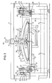
- Fig. 1
- eine schematisch vereinfachte perspektivische Ansicht einer erfindungsgemäßen Kalottenschneidmaschine;
- Fig. 2
- eine Draufsicht auf ein Tischgestell für eine erfindungsgemäße Kalottenschneidmaschine;
- Fig. 3
- eine Vorderansicht einer Kalottenschneidmaschine mit dem in Fig. 2 gezeigten Tischgestell;
- Fig. 4
- eine Seitenansicht der in Fig. 3 gezeigten Kalottenschneidmaschine;
- Fig. 5
- eine schematisch vereinfachte perspektivische Ansicht eines weiteren Ausführungsbeispieles einer erfindungsgemäßen Kalottenschneidmaschine;
- Fig. 6
- eine Unteransicht des Tischrahmens und der Schneidplatte der in Fig. 5 gezeigten Kalottenschneidmaschine;
- Fig. 7
- eine schematisch sehr vereinfachte seitliche Teilansicht des in Fig. 6 gezeigten Tischrahmens und der Schneidplatte.
Claims (25)
- Kalottenschneidmaschine zum Schneiden von Glaskalotten miteinem Schneidkopfhalter (75) miteinem ortsfesten Schneidelement (76),einem Schneidtisch (1) mit einer gewölbten Schneidplatte (5) zur Aufnahme einer Glaskalotte, wobei die Schneidplatte (5) derart gelagert und durch eine Antriebseinheit antreibbar ist, daß sie entlang einer durch ihre Oberläche festgelegten gewölbten Fläche in zwei zueinander senkrechten Richtungen während des Schneidens unter dem Schneidelement hin und her bewegbar ist, undeiner Steuereinrichtung, die die Antriebseinheit so steuert, daß die Schneidplatte (5) unter dem ortsfesten Schneidkopfhalter (75) entlang einer vorbestimmten Schnittlinie bewegt wird.
- Kalottenschneidmaschine nach Anspruch 1,
dadurch gekennzeichnet,
daß das Schneidelement (76) ein Schneidrad (79) ist und um eine vertikale Achse (80) drehbar im Schneidkopfhalter (71) gelagert ist und dessen Drehstellung von der Steuereinrichtung gesteuert wird. - Kalottenschneidmaschine nach Anspruch 1 und/oder Anspruch 2,
dadurch gekennzeichnet,
daß die Schneidplatte (5) um eine vertikale Achse (93) drehbar gelagert ist und deren Drehstellung von der Steuereinrichtung gesteuert wird. - Kalottenschneidmaschine nach Anspruch 2 und/oder 3,
dadurch gekennzeichnet,
daß der Schneidkopfhalter (75) einen Servomotor (81) zum Einstellen der Drehstellung des Schneidrades (79) aufweist. - Kalottenschneidmaschine nach einem oder mehreren der Ansprüche 1 bis 4,
dadurch gekennzeichnet,
daß der Schneidtisch (1) ein Maschinengestell (2) aufweist, an dem zwei erste Konsolen (14) zur Lagerung eines Hängerahmens (3) befestigt sind, die parallel zueinander an Randbereichen des Schneidtisches (1) angeordnet sind, wobei an den ersten Konsolen (14) eine bogenförmige Oberkante (15) als Führungsbahn ausgebildet ist, auf der der Hängerahmen (3) mit Gleit- bzw. Führungsrollen (16,17) verrollbar lagert. - Kalottenschneidmaschine nach Anspruch 5,
dadurch gekennzeichnet,
daß die Oberkante (15) konvex gewölbt ist. - Kalottenschneidmaschine nach Anspruch 5 und/oder Anspruch 6,
dadurch gekennzeichnet,
daß die Oberkante (15) kreisbogenförmig geformt ist, wobei vorzugsweise der höchste Punkt der Oberkante (15) in der Längsmitte der Konsole (14) angeordnet ist. - Kalottenschneidmaschine nach einem oder mehreren der Ansprüche 5 bis 7,
dadurch gekennzeichnet,
daß an den beiden Konsolen (14) jeweils ein Riemen (40,40') vorgesehen ist, der ortsfest angeordnet ist und ein oberer Trum (41) davon etwa parallel zur Oberkante (15) auf einer Laufbahn (38) einer bogenförmigen Schiene (37) geführt ist, wobei der Hängerahmen (3) mittels zweier Antriebsrollen (50) mit jeweils einem der beiden Riemen im Bereich seines oberen Trums in Eingriff steht, so daß duch eine Drehbewegung der Antriebsrollen (50) der Hängerahmen (3) entlang der Oberkante (15) bewegt wird. - Kalottenschneidmaschine nach Anspruch 8,
dadurch gekennzeichnet,
daß der Riemen (40) als endlos geführter Riemen ausgebildet ist. - Kalottenschneidmaschine nach Anspruch 8,
dadurch gekennzeichnet,
daß der Riemen (40') zwei Enden aufweist, die jeweils an einem Spannkörper (85) befestigt sind, die parallel zu den oberen Maschinenquerstreben (12) des Maschinengestells (2) bzw. parallel zu und auf den Hängerahmenlängsstreben (22) des Hängerahmens (3) verschiebbar und fixierbar angeordnet sind. - Kalottenschneidmaschine nach einem oder mehreren der Ansprüche 8 bis 11,
dadurch gekennzeichnet,
daß die beiden Antriebsrollen (50) von einem Elektromotor (53) angetrieben werden, der mittels einer Welle (56), die sich über den gesamten Bereich zwischen den beiden Konsolen (14) erstreckt, eine Drehbewegung überträgt, so daß die beiden Antriebsrollen (50) synchron angetrieben werden. - Kalottenschneidmaschine nach einem oder mehreren der Ansprüche 5 bis 11,
dadurch gekennzeichnet,
daß der Hängerahmen (3) aus einer Rahmenkonstruktion mit zwei Hängerahmenlängsstreben (18) und zwei Hängerahmenquerstreben (19) besteht, wobei die Hängerahmenquerstreben (19) etwas kürzer als der Abstand zwischen den Hängerahmenlängsstreben (18) und oberhalb der Hängerahmenlängsstreben (18) angeordnet sind, und die Enden der Hängerahmenlängsstreben (18) mit den Enden der Hängerahmenquerstreben (19) jeweils über kurze, schräg verlaufende Verbindungsstreben (20) verbunden sind. - Kalottenschneidmaschine nach einem oder mehreren der Ansprüche 5 bis 12,
dadurch gekennzeichnet,
daß am Hängerahmen (3) zwei zweite Konsolen (23) zur Lagerung eines Tischrahmens (4) vorgesehen sind, der die Schneidplatte (5) trägt, wobei die zweiten Konsolen (23) senkrecht zu den von den ersten Konsolen (14) festgelegten Ebenen angeordnet sind und an den zweiten Konsolen (23) jeweils eine als Führungsbahn dienende gewölbte Oberkante (25) ausgebildet ist, auf die der Tischrahmen (4) mit Lauf- bzw. Führungsrollen (26, 27) lagert. - Kalottenschneidmaschine nach Anspruch 13,
dadurch gekennzeichnet,
daß die Oberkanten (25) der zweiten Konsolen (23) konvex gewölbt sind. - Kalottenschneidmaschine nach Anspruch 13 und/oder 14,
dadurch gekennzeichnet,
daß die Wölbungen der Oberkanten (15, 25) der Konsolen (14, 23) den Wölbungen der Schneidplatte (5) an mittigen, sich durch das Zentrum der Schneidplatte (5) verlaufenden Schnittflächen entsprechen, die jeweils parallel zu den entsprechenden Konsolen (14 bzw. 23) ausgerichtet sind, wobei zumindest die Wölbung der Oberkanten (15) der ersten Konsolen (14) oder die Wölbung der Oberkante (25) der zweiten Konsolen (23) kreisbogenförmig ist. - Kalottenschneidmaschine nach einem oder mehreren der Ansprüche 13 bis 15,
dadurch gekennzeichnet,
daß die Oberkante (25) der zweiten Konsolen (23) die Form eines Bogenabschnittes einer Ellipse aufweist. - Kalottenschneidmaschine nach einem oder mehreren der Ansprüche 13 bis 16,
dadurch gekennzeichnet,
daß die Oberkante (25) der zweiten Konsolen (23) kreisbogenförmig geformt ist, wobei der höchste Punkt der Oberkante (25) in der Längsmitte der Konsole (23) angeordnet ist. - Kalottenschneidmaschine nach einem oder mehreren der Ansprüche 13 bis 17,
dadurch gekennzeichnet,
daß an den beiden zweiten Konsolen (23) jeweils ein endlos geführter Riemen (40) vorgesehen ist, der ortsfest angeordnet ist und mit einem oberen Trum (41) etwa parallel zur Oberkante (25) auf einer Laufbahn (38) einer bogenförmigen Schiene (37) der zweiten Konsolen (23) verläuft, wobei der Tischrahmen (4) mittels zweier Antriebsrollen (50) mit jeweils einem der beiden Riemen (40) im Bereich der oberen Trume (41) in Eingriff steht, so daß durch eine Drehbewegung der Antriebsrollen (40) der Tischrahmen (4) entlang der Oberkanten (25) bewegt wird. - Kalottenschneidmaschine nach Anspruch 18,
dadurch gekennzeichnet,
daß die beiden Antriebsrollen (50) von einem Elektromotor (54) angetrieben werden, der mittels einer Welle (72), die sich über den gesamten Bereich zwischen den beiden zweiten Konsolen (23) erstreckt, eine Drehbewegung überträgt, so daß die beiden Antriebsrollen (50) synchron angetrieben werden. - Kalottenschneidmaschine nach Anspruch 19,
dadurch gekennzeichnet,
daß der Tischrahmen (4) aus einem rechteckigen Rahmen besteht, der durch zwei Tischrahmenlängsstreben (28) und zwei Tischrahmenquerstreben (29) ausgebildet ist, wobei die Welle in zwei in den Tischrahmenlängsstreben (28) integrierten Lagerbuchsen (73) gelagert ist. - Kalottenschneidmaschine nach einem oder mehreren der Ansprüche 13 bis 20,
dadurch gekennzeichnet,
daß im Zentrum des Tischrahmens (4) ein Saugkopf (31) angeordnet ist, mit dem über ein Loch (74) in der Schneidplatte (5) eine Glaskalotte angesaugt werden kann. - Verfahren zum Schneiden einer Glaskalotte insbesondere mit einer Kalottenschneidmaschine nach einem oder mehreren der Ansprüche 1 bis 21,
dadurch gekennzeichnet,
daß die Glaskalotte auf eine Schneidplatte aufgelegt wird, ein senkrecht zur Oberfläche der Glaskalotte ausgerichtetes Schneidelement an die Glaskalotte angelegt wird, und die Glaskalotte durch Bewegen der Schneidplatte unter dem Schneidelement derart verfahren wird, daß vorbestimmte Schnittlinien in die Glaskalotte eingebracht werden, wobei die Bewegung der Glaskalotte entlang einer durch ihre Oberlfläche festgelegten gewölbten Fläche geführt wird. - Verfahren nach Anspruch 22,
dadurch gekennzeichnet,
daß beim Schneiden von gekrümmten Schnittlinienbereichen ein als Schneidelement verwendetes Schneidrad entsprechend gedreht wird, so daß es immer in Richtung der Schnittlinie rollt. - Verfahren nach Anspruch 22 und/oder 23,
dadurch gekennzeichnet,
daß beim Schneiden von gekrümmten Schnittlinienbereichen die Schnittgeschwindigkeit im Vergleich zum Schneiden von geradlinigen Schnittlinienbereichen gesenkt wird. - Verfahren nach einem oder mehreren der Ansprüche 22 bis 24,
dadurch gekennzeichnet,
daß aus einer Glaskalotte in einem Arbeitsvorgang mehrere Formschnitte für jeweils ein auszuschneidendes Glasteil eingebracht werden, wobei bei diesem einen Arbeitsvorgang auch Freischnitte eingebracht werden.
Applications Claiming Priority (2)
| Application Number | Priority Date | Filing Date | Title |
|---|---|---|---|
| DE19530503 | 1995-08-18 | ||
| DE19530503A DE19530503A1 (de) | 1995-08-18 | 1995-08-18 | Kalottenschneidmaschine |
Publications (2)
| Publication Number | Publication Date |
|---|---|
| EP0761615A1 EP0761615A1 (de) | 1997-03-12 |
| EP0761615B1 true EP0761615B1 (de) | 2000-03-08 |
Family
ID=7769862
Family Applications (1)
| Application Number | Title | Priority Date | Filing Date |
|---|---|---|---|
| EP96113096A Expired - Lifetime EP0761615B1 (de) | 1995-08-18 | 1996-08-14 | Maschine zum Schneiden von gewölbten Glasscheiben |
Country Status (3)
| Country | Link |
|---|---|
| EP (1) | EP0761615B1 (de) |
| DE (2) | DE19530503A1 (de) |
| ES (1) | ES2143692T3 (de) |
Families Citing this family (5)
| Publication number | Priority date | Publication date | Assignee | Title |
|---|---|---|---|---|
| IT1397279B1 (it) * | 2009-10-27 | 2013-01-04 | Biesse Spa | Macchina e procedimento per eseguire operazioni di taglio su una lastra di vetro, in particolare una lastra di vetro stratificato, lungo una traiettoria predeterminata |
| JP6855780B2 (ja) * | 2016-01-22 | 2021-04-07 | Agc株式会社 | 曲面ガラス加工装置 |
| CN113320322B (zh) * | 2021-06-29 | 2024-06-07 | 百能数控设备(福建)有限公司 | 一种大版玻璃双头刻花机 |
| CN114477751B (zh) * | 2022-02-24 | 2022-12-30 | 江苏瑞特钢化玻璃制品有限公司 | 一种玻璃切割磨边一体化设备 |
| CN119191697B (zh) * | 2024-11-29 | 2025-06-24 | 江苏联丰温室工程有限公司 | 一种用于玻璃温室搭建的玻璃切割装置 |
Family Cites Families (11)
| Publication number | Priority date | Publication date | Assignee | Title |
|---|---|---|---|---|
| FR639707A (fr) * | 1927-01-24 | 1928-06-28 | Machine à couper les verres d'optique | |
| FR34051E (fr) * | 1927-03-10 | 1929-05-01 | Machine à couper les verres d'optique | |
| US1765846A (en) * | 1929-02-23 | 1930-06-24 | Pittsburgh Plate Glass Co | Machine for severing composite glass and the like |
| US2137112A (en) * | 1938-02-15 | 1938-11-15 | Pittsburgh Plate Glass Co | Apparatus for cutting curved glass sheets |
| US3880029A (en) * | 1973-08-22 | 1975-04-29 | Ppg Industries Inc | Method for ganged scoring of glass |
| US3859878A (en) * | 1973-08-22 | 1975-01-14 | Ppg Industries Inc | Apparatus for ganged scoring of glass |
| SU990695A1 (ru) * | 1981-08-17 | 1983-01-23 | Орловское Государственное Специальное Проектно-Конструкторское Бюро По Проектированию Технологического Оборудования Для Стекольного Производства Министерства Машиностроения Для Легкой И Пищевой Промышленности И Бытовых Приборов Ссср | Устройство дл вырезки фигурных стекол |
| DE3415264A1 (de) * | 1984-04-24 | 1985-10-31 | Harald 4712 Werne Frieling | Vorrichtung zum schneiden bzw. zur oberflaechenbearbeitung von flachglas |
| AT399867B (de) * | 1990-01-11 | 1995-08-25 | Lisec Peter | Anlage zur herstellung von isolierglasscheiben |
| EP0550408B1 (de) * | 1990-01-31 | 1997-01-15 | Bando Kiko Co. Ltd. | Maschine zum Bearbeiten von Glasscheiben |
| JPH0517175A (ja) * | 1991-07-09 | 1993-01-26 | Shirai Tekkosho:Kk | 曲げガラスの切断機 |
-
1995
- 1995-08-18 DE DE19530503A patent/DE19530503A1/de not_active Withdrawn
-
1996
- 1996-08-14 EP EP96113096A patent/EP0761615B1/de not_active Expired - Lifetime
- 1996-08-14 DE DE59604584T patent/DE59604584D1/de not_active Expired - Fee Related
- 1996-08-14 ES ES96113096T patent/ES2143692T3/es not_active Expired - Lifetime
Also Published As
| Publication number | Publication date |
|---|---|
| ES2143692T3 (es) | 2000-05-16 |
| DE59604584D1 (de) | 2000-04-13 |
| DE19530503A1 (de) | 1997-02-20 |
| EP0761615A1 (de) | 1997-03-12 |
Similar Documents
| Publication | Publication Date | Title |
|---|---|---|
| DE4309327C2 (de) | Schneidvorrichtung für Schaumschwämme mit unregelmäßigen Umrissen | |
| DE3926532C2 (de) | ||
| EP0743395B1 (de) | Vorrichtung zum Schleifen von Schienen | |
| DE4116568C2 (de) | Verfahren und Vorrichtung zum gleichzeitigen Schleifen von Kurbelzapfenlagern an einer Kurbelwelle | |
| DE2145062B2 (de) | Vorrichtung zur Herstellung von Formschnitten an Werkstücken aus elastischem Material mittels einer Schablone | |
| DE2800902A1 (de) | Schneidmaschine zum schneiden einer mehrfach gekruemmten flaeche an einem werkstueck | |
| DE102005020468A1 (de) | Niederhalter für Maschinen | |
| DE10158646A1 (de) | Vorrichtung zum Besäumen von Glastafeln | |
| DE2657757C2 (de) | Vorrichtung zum Zuschneiden von Verbundglasplatten | |
| DE69316776T2 (de) | Schneidmaschine ausgerüstet mit einem rotierenden rundschneidmesser zum schneiden eines biegsamen materials in form eines einzelnen blattes oder eines kleinen blattstapels, sowie verfahren zur einstellung einer solchen maschine | |
| EP1122040B1 (de) | Formschneidmaschine mit im Bogen schwenkbarem Messerträger | |
| WO2005014497A1 (de) | Glasschneidetisch | |
| EP1400629B1 (de) | Schleifmaschine für Schienen, insbesondere für Containerkranschienen | |
| EP0761615A1 (de) | Maschine zum Schneiden von gewölbten Glasscheiben | |
| DE68917706T2 (de) | Schleifvorrichtung für Schienen. | |
| DE1658304B2 (de) | Maschine zum abschleifen des schweissgrates von stumpfgeschweissten, nichtverlegten schienen | |
| DE3631401A1 (de) | Laengsfuehrung, insbesondere fuer positionierbare anschlageinrichtungen | |
| EP0362833A2 (de) | Holzbearbeitungsmaschine, insbesondere Kehlmaschine | |
| EP0595052A2 (de) | Fahrgeschäft | |
| DE3123502C2 (de) | Maschine zum Feinbearbeiten der Zahnflanken von verzahnten Werkstücken | |
| DE4331246A1 (de) | Tisch-Kreissägemaschine | |
| DE1944565C3 (de) | Vorrichtung zum Festlegen eines Steines während seiner Bearbeitung | |
| DE2331526A1 (de) | Gekruemmtes rollengeruest fuer eine stranggiessmaschine und verfahren zu seinem zusammenbau | |
| DE3721031C2 (de) | ||
| DE4222992C2 (de) | Steinschneidevorrichtung |
Legal Events
| Date | Code | Title | Description |
|---|---|---|---|
| PUAI | Public reference made under article 153(3) epc to a published international application that has entered the european phase |
Free format text: ORIGINAL CODE: 0009012 |
|
| AK | Designated contracting states |
Kind code of ref document: A1 Designated state(s): DE ES FR GB IT |
|
| 17P | Request for examination filed |
Effective date: 19970228 |
|
| 17Q | First examination report despatched |
Effective date: 19990105 |
|
| GRAG | Despatch of communication of intention to grant |
Free format text: ORIGINAL CODE: EPIDOS AGRA |
|
| GRAG | Despatch of communication of intention to grant |
Free format text: ORIGINAL CODE: EPIDOS AGRA |
|
| GRAH | Despatch of communication of intention to grant a patent |
Free format text: ORIGINAL CODE: EPIDOS IGRA |
|
| GRAH | Despatch of communication of intention to grant a patent |
Free format text: ORIGINAL CODE: EPIDOS IGRA |
|
| GRAA | (expected) grant |
Free format text: ORIGINAL CODE: 0009210 |
|
| AK | Designated contracting states |
Kind code of ref document: B1 Designated state(s): DE ES FR GB IT |
|
| ITF | It: translation for a ep patent filed | ||
| REF | Corresponds to: |
Ref document number: 59604584 Country of ref document: DE Date of ref document: 20000413 |
|
| ET | Fr: translation filed | ||
| GBT | Gb: translation of ep patent filed (gb section 77(6)(a)/1977) |
Effective date: 20000419 |
|
| REG | Reference to a national code |
Ref country code: ES Ref legal event code: FG2A Ref document number: 2143692 Country of ref document: ES Kind code of ref document: T3 |
|
| PG25 | Lapsed in a contracting state [announced via postgrant information from national office to epo] |
Ref country code: GB Free format text: LAPSE BECAUSE OF NON-PAYMENT OF DUE FEES Effective date: 20000814 |
|
| PG25 | Lapsed in a contracting state [announced via postgrant information from national office to epo] |
Ref country code: ES Free format text: LAPSE BECAUSE OF NON-PAYMENT OF DUE FEES Effective date: 20000815 |
|
| PLBE | No opposition filed within time limit |
Free format text: ORIGINAL CODE: 0009261 |
|
| STAA | Information on the status of an ep patent application or granted ep patent |
Free format text: STATUS: NO OPPOSITION FILED WITHIN TIME LIMIT |
|
| 26N | No opposition filed | ||
| GBPC | Gb: european patent ceased through non-payment of renewal fee |
Effective date: 20000814 |
|
| PG25 | Lapsed in a contracting state [announced via postgrant information from national office to epo] |
Ref country code: FR Free format text: LAPSE BECAUSE OF NON-PAYMENT OF DUE FEES Effective date: 20011031 |
|
| REG | Reference to a national code |
Ref country code: FR Ref legal event code: ST |
|
| PGFP | Annual fee paid to national office [announced via postgrant information from national office to epo] |
Ref country code: DE Payment date: 20021024 Year of fee payment: 7 |
|
| PG25 | Lapsed in a contracting state [announced via postgrant information from national office to epo] |
Ref country code: DE Free format text: LAPSE BECAUSE OF NON-PAYMENT OF DUE FEES Effective date: 20040302 |
|
| REG | Reference to a national code |
Ref country code: ES Ref legal event code: FD2A Effective date: 20010911 |
|
| PG25 | Lapsed in a contracting state [announced via postgrant information from national office to epo] |
Ref country code: IT Free format text: LAPSE BECAUSE OF NON-PAYMENT OF DUE FEES;WARNING: LAPSES OF ITALIAN PATENTS WITH EFFECTIVE DATE BEFORE 2007 MAY HAVE OCCURRED AT ANY TIME BEFORE 2007. THE CORRECT EFFECTIVE DATE MAY BE DIFFERENT FROM THE ONE RECORDED. Effective date: 20050814 |
|
| PG25 | Lapsed in a contracting state [announced via postgrant information from national office to epo] |
Ref country code: FR Free format text: LAPSE BECAUSE OF NON-PAYMENT OF DUE FEES Effective date: 20000831 |