EP0761602B1 - Anlage zur Wasserbehandlung - Google Patents
Anlage zur Wasserbehandlung Download PDFInfo
- Publication number
- EP0761602B1 EP0761602B1 EP96113526A EP96113526A EP0761602B1 EP 0761602 B1 EP0761602 B1 EP 0761602B1 EP 96113526 A EP96113526 A EP 96113526A EP 96113526 A EP96113526 A EP 96113526A EP 0761602 B1 EP0761602 B1 EP 0761602B1
- Authority
- EP
- European Patent Office
- Prior art keywords
- flow
- valve
- line
- valve body
- valve seat
- Prior art date
- Legal status (The legal status is an assumption and is not a legal conclusion. Google has not performed a legal analysis and makes no representation as to the accuracy of the status listed.)
- Expired - Lifetime
Links
Images

Classifications
-
- C—CHEMISTRY; METALLURGY
- C02—TREATMENT OF WATER, WASTE WATER, SEWAGE, OR SLUDGE
- C02F—TREATMENT OF WATER, WASTE WATER, SEWAGE, OR SLUDGE
- C02F1/00—Treatment of water, waste water, or sewage
- C02F1/42—Treatment of water, waste water, or sewage by ion-exchange
-
- C—CHEMISTRY; METALLURGY
- C02—TREATMENT OF WATER, WASTE WATER, SEWAGE, OR SLUDGE
- C02F—TREATMENT OF WATER, WASTE WATER, SEWAGE, OR SLUDGE
- C02F2301/00—General aspects of water treatment
- C02F2301/04—Flow arrangements
- C02F2301/043—Treatment of partial or bypass streams
Definitions
- the invention relates to a system for treatment, in particular Soften water, according to the preamble of claim 1.
- a problem with the known system is that the Flow through the measuring cell to determine the current one Hardness levels or cell regeneration not in everyone Operating state is sufficient to ensure a sufficiently safe measurement or Get regeneration result. As the cause of one insufficient flow has been recognized that under a certain pressure drop along the main flow line of the Pressure gradient at the measuring cell is too low.
- the invention is therefore based on the object Flow through the measuring cell largely independent of to secure that of the ion-exchanging medium, a safe one especially at low pressure drops To ensure flow.
- the organ throttling the main flow independent of flow causes a relative decrease in the bypass resistance, for sufficient flow through the measuring cell leads.
- a preferred embodiment of the system according to the invention is in characterized claims 2 to 4.
- the invention is based on the drawing exemplified preferred embodiment of a Water softening system according to the invention in detail explained.
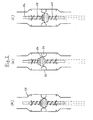
- the throttle element is a throttle valve 40 (see FIG. 2) and has a widening the cross section of the line 42 cylindrical housing 50, in the axial center thereof annular valve seat 52 and a precise fit to shut off through this axially movable, piston-like valve body 54 are arranged in the main or its counterflow if it is in one or the other flow direction is axially removed from the valve seat 52, and which is by means of two sitting on an axial piston guide rod 56 Coil springs 58 and 60 in the seat 52 in the static If there is no flow through the Throttle valve takes place.
- the throttle valve 40 When softening as well as when regenerating with brine and when washing the same, the throttle valve 40 changes its State from a to b, on the other hand from a to c during backwashing, when valves 16, 17 and 24 open, the remaining valves 19, 20 and 33 but are closed. -
- the throttle valve 40 is always effective when there is a flow, no matter in which of the two possible directions.
Landscapes
- Life Sciences & Earth Sciences (AREA)
- Hydrology & Water Resources (AREA)
- Engineering & Computer Science (AREA)
- Environmental & Geological Engineering (AREA)
- Water Supply & Treatment (AREA)
- Chemical & Material Sciences (AREA)
- Organic Chemistry (AREA)
- Treatment Of Water By Ion Exchange (AREA)
- Water Treatment By Sorption (AREA)
Description
- Fig. 1
- ein Schaltbild der ganzen Anlage; und
- Fig. 2 a - c
- drei schematische Längsschnitte eines
Drosselorgans der Anlage in drei inneren
Zuständen:
- (a) außer Betrieb
- (b) Enthärtungs-lRegenerierbetrieb
- (c) Rückspülbetrieb
- 14
- Zuführleitung
- 18
- Abflussleitung
- 21
- Sole-Injektor
- 22
- Sole-Tank
- 23
- Einlassleitung
- 25
- Luft-Rückschlagventil
- 35
- Tauchfilter
Claims (4)
- Anlage zum Behandeln, insbesondere Enthärten, von Wasser durch Ionenaustausch in einem regenerierbaren Medium, mit einem Ionentauscher (11), einer Zuführleitung (13) für zu behandelndes Wasser, einer Hauptströmungsleitung (42) für die Hauptströmung und einer Verbindungsleitung (32) für eine Nebenströmung, wobei die Hauptströmungsleitung (42) und die Verbindungsleitung (32) parallel zueinander verlaufen und aus dem Ionentauscher (11) ausmünden und an einer Stelle (44) zusammengeführt sind, wobei in der Verbindungsleitung (32) eine Messzelle (29) angeordnet ist, dadurch gekennzeichnet, dass in der Hauptströmungsleitung (42) ein Drosselorgan (40) angeordnet ist, welches im Wesentlichen durchflussunabhängig den Strömungswiderstand in der Hauptströmungsleitung (42) erhöht und dadurch den Druckabfall in der Messzelle (29) erhöht, indem das Drosselorgan (40) sowohl bei einem geringen Volumenstrom als auch bei einem hohen Volumenstrom durch die Hauptströmungsleitung (42) einen Durchflusswiderstand aufbaut, und das Drosselorgan (40) einen ringförmigen Ventilsitz (52) aufweist, dass im Ventilsitz (52) ein passgenau durch diesen bewegbarer Ventilkörper (54) angeordnet ist, dass der Ventilkörper (54) in der Hauptströmung oder in der Gegenströmung liegt, falls er in der einen bzw. in der anderen Strömungsrichtung vom Ventilsitz (52) entfernt wird, dass zwischen Ventilsitz (52) und Ventilkörper (54) ein Ventilspalt sich befindet und dass über die Strömung durch das Drosselorgan (40) der Ventilkörper (54) aus dem Ventilsitz (52) unter Vergrößerung des Ventilspaltes entgegen einer Feder (58, 60) und/oder eines Gewichtes herausbewegbar ist.
- Anlage nach Anspruch 1, dadurch gekennzeichnet, dass der Durchflusswiderstand im Drosselorgan (40) abhängig vom Volumenstrom selbsttätig verstellbar ist.
- Anlage nach Anspruch 1 oder 2, dadurch gekennzeichnet, dass bei statischem Gleichgewicht, wenn keine Strömung stattfindet, sich der Ventilkörper (54) mit Ventilspalt im Ventilsitz (52) befindet.
- Anlage nach Anspruch 1, 2 oder 3, dadurch gekennzeichnet, dass das Drosselorgan (40) vertikal durchströmbar ist und auf dem Ventilkörper (54) ein Gewicht sitzt, während an der Unterseite des Ventilkörpers (54) eine vertikal wirkende Schraubenfeder (60) angreift.
Applications Claiming Priority (2)
| Application Number | Priority Date | Filing Date | Title |
|---|---|---|---|
| DE19532074 | 1995-08-31 | ||
| DE19532074A DE19532074A1 (de) | 1995-08-31 | 1995-08-31 | Verfahren und Anlage zur Wasserbehandlung |
Publications (3)
| Publication Number | Publication Date |
|---|---|
| EP0761602A2 EP0761602A2 (de) | 1997-03-12 |
| EP0761602A3 EP0761602A3 (de) | 1997-05-07 |
| EP0761602B1 true EP0761602B1 (de) | 2000-05-17 |
Family
ID=7770868
Family Applications (1)
| Application Number | Title | Priority Date | Filing Date |
|---|---|---|---|
| EP96113526A Expired - Lifetime EP0761602B1 (de) | 1995-08-31 | 1996-08-23 | Anlage zur Wasserbehandlung |
Country Status (4)
| Country | Link |
|---|---|
| US (1) | US5798045A (de) |
| EP (1) | EP0761602B1 (de) |
| AT (1) | ATE192998T1 (de) |
| DE (2) | DE19532074A1 (de) |
Citations (1)
| Publication number | Priority date | Publication date | Assignee | Title |
|---|---|---|---|---|
| DE3625337A1 (de) * | 1985-08-13 | 1987-02-19 | Spiegl Karl | Wasserenthaertungsanlage |
Family Cites Families (9)
| Publication number | Priority date | Publication date | Assignee | Title |
|---|---|---|---|---|
| FR1093901A (fr) * | 1954-02-25 | 1955-05-10 | Dispositif régulateur de débit | |
| CH505028A (fr) * | 1968-07-26 | 1971-03-31 | Sapir S A | Dispositif de vanne pour appareil adoucisseur d'eau |
| BE814058A (fr) * | 1973-05-10 | 1974-08-16 | Systeme adoucisseur d'eau | |
| FR2448746A1 (fr) * | 1979-02-08 | 1980-09-05 | Etude Realisa Equip Speciaux | Dispositifs pour maintenir dans un rapport constant les debits instantanes de deux fluides et applications |
| JPS55118109A (en) * | 1979-03-06 | 1980-09-10 | Ebara Corp | Two-fluids ratio flowing amount adjuster |
| DE2910869C2 (de) * | 1979-03-20 | 1984-01-26 | Spiegl, Karl, 7031 Aidlingen | Anlage zum Enthärten von Wasser |
| US4385992A (en) * | 1981-06-29 | 1983-05-31 | Autotrol Corporation | Water softener control |
| DE3528617A1 (de) * | 1985-08-09 | 1987-05-14 | Kurt Michael Desch | Steuerung fuer auch nur teilbeladene wasseraufbereitungsanlagen mit mess- und/oder pruefstellen fuer das wasser und/oder die austauschermasse zur anpassung der regelmaessigen regenerationen an den jeweiligen erschoepfungsgrad der gesamt-austauschermasse |
| US5069779A (en) * | 1989-12-15 | 1991-12-03 | Kinetico, Incorporated | Water treatment system |
-
1995
- 1995-08-31 DE DE19532074A patent/DE19532074A1/de not_active Withdrawn
-
1996
- 1996-08-23 EP EP96113526A patent/EP0761602B1/de not_active Expired - Lifetime
- 1996-08-23 AT AT96113526T patent/ATE192998T1/de not_active IP Right Cessation
- 1996-08-23 DE DE59605229T patent/DE59605229D1/de not_active Expired - Lifetime
- 1996-08-29 US US08/705,409 patent/US5798045A/en not_active Expired - Lifetime
Patent Citations (1)
| Publication number | Priority date | Publication date | Assignee | Title |
|---|---|---|---|---|
| DE3625337A1 (de) * | 1985-08-13 | 1987-02-19 | Spiegl Karl | Wasserenthaertungsanlage |
Non-Patent Citations (1)
| Title |
|---|
| "Brockhaus Enzyklopädie", 19. Aufl., F.A. Brockhaus, Mannheim 1987, Bd. 3, Seiten 166-7 & 272-3 * |
Also Published As
| Publication number | Publication date |
|---|---|
| EP0761602A2 (de) | 1997-03-12 |
| DE59605229D1 (de) | 2000-06-21 |
| ATE192998T1 (de) | 2000-06-15 |
| DE19532074A1 (de) | 1997-03-06 |
| US5798045A (en) | 1998-08-25 |
| EP0761602A3 (de) | 1997-05-07 |
Similar Documents
| Publication | Publication Date | Title |
|---|---|---|
| DE2419296A1 (de) | Reinigungsvorrichtung fuer ein fluessigkeitsstroemungssystem mit einer rohrleitungsanlage | |
| DE1519995A1 (de) | Apparat zum Fraktionieren von Gasgemischen | |
| DE4124040C2 (de) | Hydraulischer Schwingungsdämpfer für Fahrzeuge | |
| DE102007037525A1 (de) | Ölfiltersystem und Verfahren zum Betreiben eines Ölfiltersystems | |
| DE1179124B (de) | Vorrichtung zur Kurvenstabilisierung des Wagenkastens bei Kraftfahrzeugen | |
| DE7017829U (de) | Filtereinrichtung. | |
| EP0761602B1 (de) | Anlage zur Wasserbehandlung | |
| DE2016803A1 (de) | Düse für zwei entgegengesetzte Durchflußrichtungen mit unterschiedlichen Durchflußquerschnitten, sowie deren Verwendung | |
| DE1436259B2 (de) | ; Filter | |
| DE6803222U (de) | Vorrichtung zum kontinuierlichen behandeln einer fluessigkeit mit einem ionenaustauschenden stoff. | |
| DE60035193T2 (de) | Behälter zur enthärtung von wasser | |
| DE2834437A1 (de) | Enthaertungseinrichtung fuer haushaltgeraete, insbesondere geschirrspuel- und waschmaschinen | |
| DE3621928A1 (de) | Wasserenthaertungsgeraet | |
| DE684490C (de) | Vorrichtung zum gleichmaessigen Zu- und Abfuehren der Fluessigkeiten bei Schleudermaschinen | |
| DE3839203A1 (de) | Programmgesteuerte haushaltwaschmaschine mit wasserenthaertungseinrichtung | |
| DE19723798A1 (de) | Rückspülbare Filtereinrichtung | |
| WO2023208440A1 (de) | Verfahren zum betreiben eines fluidspeichersystems sowie fluidspeichersystem das mit einem derartigen verfahren betreibbar ist | |
| DE2422092A1 (de) | Salzsolevorratsbehaelter fuer wasserenthaertungsgeraete mit anzeige der salzsolekonzentration | |
| CH665136A5 (de) | Verfahren zur reinigung von luft- oder gasstroemen und wanderbettfilteranlage zur durchfuehrung des verfahrens. | |
| DE69631876T2 (de) | Verfahren und Vorrichtung zur Behandlung von Wasser | |
| DE4032265A1 (de) | Trinkwasser-filteranlage | |
| DE2419387A1 (de) | Wasserenthaertungsanlage | |
| DE3520743A1 (de) | Vorrichtung zur wasserentsalzung | |
| DE2136513A1 (de) | Wasserreinigungsvorrichtung | |
| DE910041C (de) | Gasdruckregler mit Steuerregler |
Legal Events
| Date | Code | Title | Description |
|---|---|---|---|
| PUAI | Public reference made under article 153(3) epc to a published international application that has entered the european phase |
Free format text: ORIGINAL CODE: 0009012 |
|
| AK | Designated contracting states |
Kind code of ref document: A2 Designated state(s): AT BE CH DE FR GB IT LI NL |
|
| PUAL | Search report despatched |
Free format text: ORIGINAL CODE: 0009013 |
|
| AK | Designated contracting states |
Kind code of ref document: A3 Designated state(s): AT BE CH DE FR GB IT LI NL |
|
| 17P | Request for examination filed |
Effective date: 19970729 |
|
| 17Q | First examination report despatched |
Effective date: 19980403 |
|
| GRAG | Despatch of communication of intention to grant |
Free format text: ORIGINAL CODE: EPIDOS AGRA |
|
| RTI1 | Title (correction) |
Free format text: INSTALLATION FOR WATER TREATMENT |
|
| GRAG | Despatch of communication of intention to grant |
Free format text: ORIGINAL CODE: EPIDOS AGRA |
|
| GRAH | Despatch of communication of intention to grant a patent |
Free format text: ORIGINAL CODE: EPIDOS IGRA |
|
| GRAH | Despatch of communication of intention to grant a patent |
Free format text: ORIGINAL CODE: EPIDOS IGRA |
|
| GRAA | (expected) grant |
Free format text: ORIGINAL CODE: 0009210 |
|
| AK | Designated contracting states |
Kind code of ref document: B1 Designated state(s): AT BE CH DE FR GB IT LI NL |
|
| PG25 | Lapsed in a contracting state [announced via postgrant information from national office to epo] |
Ref country code: FR Free format text: LAPSE BECAUSE OF FAILURE TO SUBMIT A TRANSLATION OF THE DESCRIPTION OR TO PAY THE FEE WITHIN THE PRESCRIBED TIME-LIMIT Effective date: 20000517 |
|
| REF | Corresponds to: |
Ref document number: 192998 Country of ref document: AT Date of ref document: 20000615 Kind code of ref document: T |
|
| ITF | It: translation for a ep patent filed | ||
| REG | Reference to a national code |
Ref country code: CH Ref legal event code: NV Representative=s name: TROESCH SCHEIDEGGER WERNER AG Ref country code: CH Ref legal event code: EP |
|
| GBT | Gb: translation of ep patent filed (gb section 77(6)(a)/1977) |
Effective date: 20000518 |
|
| REF | Corresponds to: |
Ref document number: 59605229 Country of ref document: DE Date of ref document: 20000621 |
|
| PG25 | Lapsed in a contracting state [announced via postgrant information from national office to epo] |
Ref country code: AT Free format text: LAPSE BECAUSE OF NON-PAYMENT OF DUE FEES Effective date: 20000823 |
|
| PG25 | Lapsed in a contracting state [announced via postgrant information from national office to epo] |
Ref country code: BE Free format text: LAPSE BECAUSE OF NON-PAYMENT OF DUE FEES Effective date: 20000831 |
|
| EN | Fr: translation not filed | ||
| BERE | Be: lapsed |
Owner name: KARL SPIEGL G.B.M.H. & CO. Effective date: 20000831 |
|
| PLBE | No opposition filed within time limit |
Free format text: ORIGINAL CODE: 0009261 |
|
| STAA | Information on the status of an ep patent application or granted ep patent |
Free format text: STATUS: NO OPPOSITION FILED WITHIN TIME LIMIT |
|
| 26N | No opposition filed | ||
| REG | Reference to a national code |
Ref country code: GB Ref legal event code: IF02 |
|
| PGFP | Annual fee paid to national office [announced via postgrant information from national office to epo] |
Ref country code: NL Payment date: 20110825 Year of fee payment: 16 Ref country code: IT Payment date: 20110825 Year of fee payment: 16 |
|
| REG | Reference to a national code |
Ref country code: NL Ref legal event code: V1 Effective date: 20130301 |
|
| PG25 | Lapsed in a contracting state [announced via postgrant information from national office to epo] |
Ref country code: NL Free format text: LAPSE BECAUSE OF NON-PAYMENT OF DUE FEES Effective date: 20130301 |
|
| PG25 | Lapsed in a contracting state [announced via postgrant information from national office to epo] |
Ref country code: IT Free format text: LAPSE BECAUSE OF NON-PAYMENT OF DUE FEES Effective date: 20120823 |
|
| PGFP | Annual fee paid to national office [announced via postgrant information from national office to epo] |
Ref country code: CH Payment date: 20130826 Year of fee payment: 18 |
|
| PGFP | Annual fee paid to national office [announced via postgrant information from national office to epo] |
Ref country code: GB Payment date: 20130805 Year of fee payment: 18 |
|
| REG | Reference to a national code |
Ref country code: CH Ref legal event code: PL |
|
| GBPC | Gb: european patent ceased through non-payment of renewal fee |
Effective date: 20140823 |
|
| PG25 | Lapsed in a contracting state [announced via postgrant information from national office to epo] |
Ref country code: LI Free format text: LAPSE BECAUSE OF NON-PAYMENT OF DUE FEES Effective date: 20140831 Ref country code: CH Free format text: LAPSE BECAUSE OF NON-PAYMENT OF DUE FEES Effective date: 20140831 |
|
| PG25 | Lapsed in a contracting state [announced via postgrant information from national office to epo] |
Ref country code: GB Free format text: LAPSE BECAUSE OF NON-PAYMENT OF DUE FEES Effective date: 20140823 |
|
| PGFP | Annual fee paid to national office [announced via postgrant information from national office to epo] |
Ref country code: DE Payment date: 20151019 Year of fee payment: 20 |
|
| REG | Reference to a national code |
Ref country code: DE Ref legal event code: R071 Ref document number: 59605229 Country of ref document: DE |