EP0761602A2 - Verfahren und Anlage zur Wasserbehandlung - Google Patents
Verfahren und Anlage zur Wasserbehandlung Download PDFInfo
- Publication number
- EP0761602A2 EP0761602A2 EP96113526A EP96113526A EP0761602A2 EP 0761602 A2 EP0761602 A2 EP 0761602A2 EP 96113526 A EP96113526 A EP 96113526A EP 96113526 A EP96113526 A EP 96113526A EP 0761602 A2 EP0761602 A2 EP 0761602A2
- Authority
- EP
- European Patent Office
- Prior art keywords
- flow
- valve
- measuring cell
- medium
- main
- Prior art date
- Legal status (The legal status is an assumption and is not a legal conclusion. Google has not performed a legal analysis and makes no representation as to the accuracy of the status listed.)
- Granted
Links
Images
Classifications
-
- C—CHEMISTRY; METALLURGY
- C02—TREATMENT OF WATER, WASTE WATER, SEWAGE, OR SLUDGE
- C02F—TREATMENT OF WATER, WASTE WATER, SEWAGE, OR SLUDGE
- C02F1/00—Treatment of water, waste water, or sewage
- C02F1/42—Treatment of water, waste water, or sewage by ion-exchange
-
- C—CHEMISTRY; METALLURGY
- C02—TREATMENT OF WATER, WASTE WATER, SEWAGE, OR SLUDGE
- C02F—TREATMENT OF WATER, WASTE WATER, SEWAGE, OR SLUDGE
- C02F2301/00—General aspects of water treatment
- C02F2301/04—Flow arrangements
- C02F2301/043—Treatment of partial or bypass streams
Definitions
- the invention relates to a method for treating, in particular softening, water, according to the preamble of claim 1, and a system for carrying out the method, according to the preamble of claim 3.
- a 3/2-way valve 60
- the bypass flow line 83
- the bypass flow line 83
- the flow through the measuring cell in order to determine the current degree of hardness or cell regeneration is not sufficient in every operating state to ensure a sufficiently reliable measuring or Get regeneration result.
- the cause of an insufficient flow has been recognized that the pressure gradient at the measuring cell is too low under a certain pressure drop along the main flow line.
- the object of the invention is therefore to ensure that the flow through the measuring cell is largely independent of that of the ion-exchanging medium. This object is achieved according to the invention by the method according to claim 1 or the system according to claim 3.
- the throttling member which restricts the main flow independently of the flow, brings about a relative reduction in the bypass resistance, which leads to sufficient flow through the measuring cell.
- a preferred implementation of the method according to the invention is characterized in claim 2.
- a preferred embodiment of the system according to the invention is characterized in claim 4 (to 6).
- the exemplary embodiment of the system according to the invention corresponds, as far as this is state of the art, to the system according to FIG. 3 of DE 36 25 337 A1 except for its 3/2-way valve (60) and its feed line (61) for brine, which are missing here.
- a throttle element 40 interrupts a water line 42, which connects the partially replaced extraction pipe 12 to the soft water discharge line 15, the test water line 83 opening at point 44 between the throttle element 40 and the check valve 17.
- - Structure and operation of the known system are described from line 59 in column 11 to line 58 in column 13 of DE 36 25 337 A1. The reference numbers used there are adopted here.
- the throttle element is a throttle valve 40 (see FIG. 2) and has a cylindrical housing 50 which widens the cross-section of the line 42, in the axial center of which an annular valve seat 52 and a piston-like valve body 54 which can be moved by means of an exact fit and which can be shut off are arranged in the main flow or its counterflow if it is axially distant from the valve seat 52 in one or the other flow direction, and which is in static equilibrium in the seat 52 by means of two coil springs 58 and 60 seated on an axial piston guide rod 56, if none Flow through the throttle valve takes place.
- the throttle valve 40 When softening as well as when regenerating with brine and when washing out, the throttle valve 40 changes its state from a to b, but from a to c during backwashing when the valves 16, 17 and 24 are open, but the other valves 19, 20 and 33 are closed. - The throttle valve 40 is therefore always effective when there is a flow, regardless of which of the two possible directions.
Landscapes
- Life Sciences & Earth Sciences (AREA)
- Hydrology & Water Resources (AREA)
- Engineering & Computer Science (AREA)
- Environmental & Geological Engineering (AREA)
- Water Supply & Treatment (AREA)
- Chemical & Material Sciences (AREA)
- Organic Chemistry (AREA)
- Treatment Of Water By Ion Exchange (AREA)
- Water Treatment By Sorption (AREA)
Abstract
Bei einer bekannten Anlage (DE 36 25 337 A1) besteht das Problem, daß die Durchströmung der Meßzelle nicht immer ausreicht, um ein sicheres Meßergebnis zu erhalten.
Aufgabe der Erfindung ist es daher, die Durchströmung der Meßzelle unabhängig von derjenigen des Mediums zu sichern.
Lösung dieser Aufgabe ist die durchflußunabhängige Drosselung der Hauptströmung und die entsprechende Erhöhung des Druckgefälles der Nebenströmung mittels eines Drosselorgans (40), das den Druckabfall in der Meßzelle durchflußunabhängig erhöht.
Die Drosselung der Hauptströmung bewirkt eine relative Erniedrigung des Nebenströmungswiderstandes und damit eine erhöhte Durchströmung der Meßzelle.
Description
- Die Erfindung betrifft ein Verfahren zum Behandeln, insbesondere Enthärten, von Wasser, gemäß Oberbegriff des Anspruchs 1 sowie eine Anlage zum Durchführen des Verfahrens, gemäß Oberbegriff des Anspruchs 3.
Bei einer entsprechenden Wasserenthärtungsanlage gemäß Fig. 3 der DE 36 25 337 A1 (Spiegl) ist in die Nebenströmungsleitung (83) ein 3/2-Wegeventil (60) geschaltet, das einen zum Regenerieren des ionenaustauschenden Mediums der Meßzelle (29) wählbaren Schaltzustand und eine die beiden Anschlußstellen der unterbrochenen Nebenströmungsleitung verbindende Schaltstellung ermöglicht, die im Folgenden vorausgesetzt wird.
Ein Problem bei der bekannten Anlage ist, daß die Durchströmung der Meßzelle zwecks Feststellung des momentanen Härtegrades oder Zellenregeneration nicht in jedem Betriebszustand ausreicht, um ein hinreichend sicheres Meß- bzw.
Regenerierungsergebnis zu erhalten. Als Ursache für eine ungenügende Durchströmung ist erkannt worden, daß unter einem bestimmten Druckabfall längs der Hauptströmungsleitung der Druckgradient an der Meßzelle zu gering ist.
Der Erfindung liegt daher die Aufgabe zugrunde, die Durchströmung der Meßzelle weitgehend unabhängig von derjenigen des ionenaustauschenden Mediums zu sichern.
Diese Aufgabe ist erfindungsgemäß gelöst durch das Verfahren gemäß Anspruch 1 bzw. die Anlage gemäß Anspruch 3. Das die Hauptströmung durchflußunabhängig drosselnde Organ bewirkt eine relative Erniedrigung des Nebenströmungswiderstandes, die zur ausreichenden Durchströmung der Meßzelle führt. - Eine bevorzugte Durchführung des erfindungsgemäßen Verfahrens ist in Anspruch 2 gekennzeichnet. Eine bevorzugte Ausführung der erfindungsgemäßen Anlage ist in Anspruch 4 (bis 6) gekennzeichnet. Alternativen dazu kennzeichnen die Ansprüche 7 und 8.
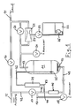
- Im Folgenden ist die Erfindung anhand der durch die Zeichnung beispielhaft dargestellten bevorzugten Ausführungsform einer erfindungsgemäßen Wasserenthärtungs-Anlage im Einzelnen erläutert. Es zeigt:
- Fig. 1
- ein Schaltbild der ganzen Anlage
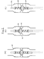
- Fig. 2
- a bis c drei schematische Längsschnitte eines Drosselorgans der Anlage in drei inneren Zuständen:
- (a) außer Betrieb
- (b) Enthärtungs-/Regenerierbetrieb
- (c) Rückspülbetrieb
- Das Ausführungsbeispiel der erfindungsgemäßen Anlage entspricht, soweit diese Stand der Technik ist, der Anlage gemäß Fig. 3 der DE 36 25 337 A1 bis auf deren 3/2-Wegeventil (60) und dessen Zuleitung (61) für Sole, die hier fehlen, wo ein Drosselorgan 40 eine Wasserleitung 42 unterbricht, die das dadurch zum Teil ersetzte Entnahmerohr 12 mit der Weichwasser-Abführleitung 15 verbindet, wobei die Prüfwasserleitung 83 zwischen Drosselorgan 40 und Sperrventil 17 an der Stelle 44 einmündet. - Aufbau und Wirkungsweise der bekannten Anlage sind von Zeile 59 der Spalte 11 bis Zeile 58 der Spalte 13 der DE 36 25 337 A1 beschrieben. Die dort verwendeten Bezugszahlen sind hier übernommen.
- Das Drosselorgan ist ein Drosselventil 40 (siehe Fig. 2) und besitzt ein den Querschnitt der Leitung 42 erweiterndes zylindrisches Gehäuse 50, in dessen axialer Mitte ein ringförmiger Ventilsitz 52 und ein zum Absperren paßgenau durch diesen axial bewegbarer, kolbenähnlicher Ventilkörper 54 angeordnet sind, der in der Haupt- oder deren Gegenströmung liegt, falls er in der einen bzw. anderen Strömungsrichtung vom Ventilsitz 52 axial entfernt ist, und welcher sich mittels zweier auf einer axialen Kolbenführungsstange 56 sitzender Schraubenfedern 58 und 60 im Sitz 52 im statischen Gleichgewicht befindet, falls keine Strömung durch das Drosselventil stattfindet.
- Beim Enthärten ebenso wie beim Regenerieren mittels Sole und beim Auswaschen derselben wechselt das Drosselventil 40 seinen Zustand von a nach b, dagegen von a nach c beim Rückspülen, wenn die Ventile 16, 17 und 24 geöffnet, die übrigen Ventile 19, 20 und 33 aber geschlossen sind. - Das Drosselventil 40 ist also stets wirksam, wenn eine Durchströmung stattfindet, gleich in welcher der beiden möglichen Richtungen.
Claims (8)
- Verfahren zum Behandeln, insbesondere Enthärten, von Wasser durch Ionenaustausch in einem regernierbaren Medium, dem enthärtetes Wasser unter Gegendruck entnommen wird, wobei die Mediumserschöpfung in einer Nebenströmung parallel zur Hauptströmung vom Medium zur Entnahmestelle gemessen wird, dadurch gekennzeichnet, daß die Hauptströmung im wesentlichen durchflußunabhängig gedrosselt und dadurch das Druckgefälle der Nebenströmung erhöht wird.
- Verfahren nach Anspruch 1, bei dem zum Regenerieren und/oder Rückspülen die Haupt- und die Nebenströmungsrichtungen umgekehrt werden, dadurch geknnzeichnet, daß die Drosselwirkung gleichfalls umgekehrt wird.
- Anlage zum Durchführen des Verfahrens nach Anspruch 1, mit einem Ionenaustauscher sowie einer Haupt- und einer Nebenströmungsleitung, die parallel geschaltet sind und vom Austausche zur Wasserentnahmestelle führen, wobei die Nebenströmungsleitung mit einer Meßzelle versehen ist, dadurch gekennzeichnet, daß in die Hauptströmungsleitung (42) ein Drosselorgan (40) geschaltet ist, welches im wesentlichen durchflußunabhängig den Druckabfall in der Meßzelle (29) erhöht (Fig. 1).
- Anlage nach Anspruch 3, zum Durchführen des Verfahrens nach Anspruch 2, gekennzeichnet durch ein selbsttätig verstellbares Drosselventil (40) als Drosselorgan (Fig. 2).
- Anlage nach Anspruch 4, dadurch gekennzeichnet, daß das Drosselventil (40) einen ringförmigen Ventilsitz (52) und zum Absperren einen paßgenau durch diesen bewegbaren Ventilkörper (54) aufweist, der in der Hauptströmung oder deren Gegenströmung liegt, falls er in der einen bzw. anderen Strömungsrichtung vom Ventilsitz (52) entfernt ist, und welcher (54) sich mittels mindestens einer Feder (58 und 60) und/oder eines Gewichtes im Sitz (52) im statischen Gleichgewicht befindet, falls keine Strömung stattfindet (Fig. 2).
- Anlage nach Anspruch 5, dadurch gekennzeichnet, daß das Drosselventil (40) vertikal durchströmbar ist und auf dem Ventilkörper (54) ein Gewicht sitzt, während an der Körperunterseite eine vertikal wirkende Schraubenfeder (60) angreift.
- Anlage nach Anspruch 3, gekennzeichnet durch ein Druckgefälleventil als Drosselorgan.
- Anlage nach Anspruch 3, zum Durchführen des Verfahrens nach Anspruch 2, gekennzeichnet, durch zwei antiparallel geschaltete Rückschlagventile.
Applications Claiming Priority (2)
| Application Number | Priority Date | Filing Date | Title |
|---|---|---|---|
| DE19532074 | 1995-08-31 | ||
| DE19532074A DE19532074A1 (de) | 1995-08-31 | 1995-08-31 | Verfahren und Anlage zur Wasserbehandlung |
Publications (3)
| Publication Number | Publication Date |
|---|---|
| EP0761602A2 true EP0761602A2 (de) | 1997-03-12 |
| EP0761602A3 EP0761602A3 (de) | 1997-05-07 |
| EP0761602B1 EP0761602B1 (de) | 2000-05-17 |
Family
ID=7770868
Family Applications (1)
| Application Number | Title | Priority Date | Filing Date |
|---|---|---|---|
| EP96113526A Expired - Lifetime EP0761602B1 (de) | 1995-08-31 | 1996-08-23 | Anlage zur Wasserbehandlung |
Country Status (4)
| Country | Link |
|---|---|
| US (1) | US5798045A (de) |
| EP (1) | EP0761602B1 (de) |
| AT (1) | ATE192998T1 (de) |
| DE (2) | DE19532074A1 (de) |
Family Cites Families (10)
| Publication number | Priority date | Publication date | Assignee | Title |
|---|---|---|---|---|
| FR1093901A (fr) * | 1954-02-25 | 1955-05-10 | Dispositif régulateur de débit | |
| CH505028A (fr) * | 1968-07-26 | 1971-03-31 | Sapir S A | Dispositif de vanne pour appareil adoucisseur d'eau |
| DE2419387A1 (de) * | 1973-05-10 | 1974-11-21 | Honeywell Inc | Wasserenthaertungsanlage |
| FR2448746A1 (fr) * | 1979-02-08 | 1980-09-05 | Etude Realisa Equip Speciaux | Dispositifs pour maintenir dans un rapport constant les debits instantanes de deux fluides et applications |
| JPS55118109A (en) * | 1979-03-06 | 1980-09-10 | Ebara Corp | Two-fluids ratio flowing amount adjuster |
| DE2910869C2 (de) * | 1979-03-20 | 1984-01-26 | Spiegl, Karl, 7031 Aidlingen | Anlage zum Enthärten von Wasser |
| US4385992A (en) * | 1981-06-29 | 1983-05-31 | Autotrol Corporation | Water softener control |
| DE3528617A1 (de) * | 1985-08-09 | 1987-05-14 | Kurt Michael Desch | Steuerung fuer auch nur teilbeladene wasseraufbereitungsanlagen mit mess- und/oder pruefstellen fuer das wasser und/oder die austauschermasse zur anpassung der regelmaessigen regenerationen an den jeweiligen erschoepfungsgrad der gesamt-austauschermasse |
| DE3625337A1 (de) * | 1985-08-13 | 1987-02-19 | Spiegl Karl | Wasserenthaertungsanlage |
| US5069779A (en) * | 1989-12-15 | 1991-12-03 | Kinetico, Incorporated | Water treatment system |
-
1995
- 1995-08-31 DE DE19532074A patent/DE19532074A1/de not_active Withdrawn
-
1996
- 1996-08-23 DE DE59605229T patent/DE59605229D1/de not_active Expired - Lifetime
- 1996-08-23 AT AT96113526T patent/ATE192998T1/de not_active IP Right Cessation
- 1996-08-23 EP EP96113526A patent/EP0761602B1/de not_active Expired - Lifetime
- 1996-08-29 US US08/705,409 patent/US5798045A/en not_active Expired - Lifetime
Also Published As
| Publication number | Publication date |
|---|---|
| ATE192998T1 (de) | 2000-06-15 |
| EP0761602A3 (de) | 1997-05-07 |
| EP0761602B1 (de) | 2000-05-17 |
| US5798045A (en) | 1998-08-25 |
| DE19532074A1 (de) | 1997-03-06 |
| DE59605229D1 (de) | 2000-06-21 |
Similar Documents
| Publication | Publication Date | Title |
|---|---|---|
| DE2910869C2 (de) | Anlage zum Enthärten von Wasser | |
| DE3126580C2 (de) | Einrichtung zum Steuern der Regenerationseinrichtung für das Ionenaustauschmaterial eines Wasserenthärters | |
| EP0031535A2 (de) | Verfahren zum zyklischen Regenerieren von Wasserenthärtungsanlagen und programmgesteuerte Wasserenthärtungsanlage zur Durchführung des Verfahrens | |
| DE3543291A1 (de) | Hydraulischer stossdaempfer | |
| DE3406724C2 (de) | Härtefühler für Wasserenthärtungsanlagen | |
| DE3913917A1 (de) | System zur filtration von fluessigkeiten mit schwebeteilchen | |
| EP0761602A2 (de) | Verfahren und Anlage zur Wasserbehandlung | |
| DE2027901A1 (de) | Verfahren zum Betreiben und Regene neren einer Anzahl Reihen miteinander verbundener Betten an Ionenaustausch material | |
| DE3124481A1 (de) | "reifendruckregelanlage" | |
| DE2834437A1 (de) | Enthaertungseinrichtung fuer haushaltgeraete, insbesondere geschirrspuel- und waschmaschinen | |
| DE3016943A1 (de) | Hydraulische anlage mit zwei pumpen | |
| EP4515109A1 (de) | Verfahren zum betreiben eines fluidspeichersystems sowie fluidspeichersystem das mit einem derartigen verfahren betreibbar ist | |
| DE4039236C1 (en) | Control valve for hydraulic shock absorber of motor vehicle - uses electromagnet to increase force of permanent magnet and open by=pass against mechanical spring force closing by=pass | |
| CH659881A5 (de) | Vorrichtung zur verteilung der absorptionsfluessigkeit in einem absorptionskuehlapparat. | |
| DE2419387A1 (de) | Wasserenthaertungsanlage | |
| DE2652113C2 (de) | ||
| DE19723798A1 (de) | Rückspülbare Filtereinrichtung | |
| DE2750658A1 (de) | Wasserenthaertungseinrichtung fuer hausgeraete, insbesondere geschirrspuelmaschinen | |
| DE19537067C1 (de) | Heiz- und/oder Klimaanlage | |
| DE2314835A1 (de) | Einrichtung zum reinigen des kondensates fuer eine hochdruckdampferzeugungsanlage | |
| DE102021109877B3 (de) | Hydraulikaggregat | |
| AT378609B (de) | Zuschaltventil zum zuschalten eines hochdruckmediums in ein mit niederdruck beaufschlagtes system | |
| EP0229918A1 (de) | Antrieb für Hochspannungs-Leistungsschalter | |
| DE1146394B (de) | Verfahren und Vorrichtung zum Fuellen von Behaeltern mit einer keimfreien Fluessigkeit | |
| DE202017001649U1 (de) | Zentralsteuerventil-Adapter für eine Ionenaustauscheranlage zur Behandlung eines Filtrats, insbesondere zur Enthärtung oder Entsalzung von Brauch- und Trinkwasser |
Legal Events
| Date | Code | Title | Description |
|---|---|---|---|
| PUAI | Public reference made under article 153(3) epc to a published international application that has entered the european phase |
Free format text: ORIGINAL CODE: 0009012 |
|
| AK | Designated contracting states |
Kind code of ref document: A2 Designated state(s): AT BE CH DE FR GB IT LI NL |
|
| PUAL | Search report despatched |
Free format text: ORIGINAL CODE: 0009013 |
|
| AK | Designated contracting states |
Kind code of ref document: A3 Designated state(s): AT BE CH DE FR GB IT LI NL |
|
| 17P | Request for examination filed |
Effective date: 19970729 |
|
| 17Q | First examination report despatched |
Effective date: 19980403 |
|
| GRAG | Despatch of communication of intention to grant |
Free format text: ORIGINAL CODE: EPIDOS AGRA |
|
| RTI1 | Title (correction) |
Free format text: INSTALLATION FOR WATER TREATMENT |
|
| GRAG | Despatch of communication of intention to grant |
Free format text: ORIGINAL CODE: EPIDOS AGRA |
|
| GRAH | Despatch of communication of intention to grant a patent |
Free format text: ORIGINAL CODE: EPIDOS IGRA |
|
| GRAH | Despatch of communication of intention to grant a patent |
Free format text: ORIGINAL CODE: EPIDOS IGRA |
|
| GRAA | (expected) grant |
Free format text: ORIGINAL CODE: 0009210 |
|
| AK | Designated contracting states |
Kind code of ref document: B1 Designated state(s): AT BE CH DE FR GB IT LI NL |
|
| PG25 | Lapsed in a contracting state [announced via postgrant information from national office to epo] |
Ref country code: FR Free format text: LAPSE BECAUSE OF FAILURE TO SUBMIT A TRANSLATION OF THE DESCRIPTION OR TO PAY THE FEE WITHIN THE PRESCRIBED TIME-LIMIT Effective date: 20000517 |
|
| REF | Corresponds to: |
Ref document number: 192998 Country of ref document: AT Date of ref document: 20000615 Kind code of ref document: T |
|
| ITF | It: translation for a ep patent filed | ||
| REG | Reference to a national code |
Ref country code: CH Ref legal event code: NV Representative=s name: TROESCH SCHEIDEGGER WERNER AG Ref country code: CH Ref legal event code: EP |
|
| GBT | Gb: translation of ep patent filed (gb section 77(6)(a)/1977) |
Effective date: 20000518 |
|
| REF | Corresponds to: |
Ref document number: 59605229 Country of ref document: DE Date of ref document: 20000621 |
|
| PG25 | Lapsed in a contracting state [announced via postgrant information from national office to epo] |
Ref country code: AT Free format text: LAPSE BECAUSE OF NON-PAYMENT OF DUE FEES Effective date: 20000823 |
|
| PG25 | Lapsed in a contracting state [announced via postgrant information from national office to epo] |
Ref country code: BE Free format text: LAPSE BECAUSE OF NON-PAYMENT OF DUE FEES Effective date: 20000831 |
|
| EN | Fr: translation not filed | ||
| BERE | Be: lapsed |
Owner name: KARL SPIEGL G.B.M.H. & CO. Effective date: 20000831 |
|
| PLBE | No opposition filed within time limit |
Free format text: ORIGINAL CODE: 0009261 |
|
| STAA | Information on the status of an ep patent application or granted ep patent |
Free format text: STATUS: NO OPPOSITION FILED WITHIN TIME LIMIT |
|
| 26N | No opposition filed | ||
| REG | Reference to a national code |
Ref country code: GB Ref legal event code: IF02 |
|
| PGFP | Annual fee paid to national office [announced via postgrant information from national office to epo] |
Ref country code: NL Payment date: 20110825 Year of fee payment: 16 Ref country code: IT Payment date: 20110825 Year of fee payment: 16 |
|
| REG | Reference to a national code |
Ref country code: NL Ref legal event code: V1 Effective date: 20130301 |
|
| PG25 | Lapsed in a contracting state [announced via postgrant information from national office to epo] |
Ref country code: NL Free format text: LAPSE BECAUSE OF NON-PAYMENT OF DUE FEES Effective date: 20130301 |
|
| PG25 | Lapsed in a contracting state [announced via postgrant information from national office to epo] |
Ref country code: IT Free format text: LAPSE BECAUSE OF NON-PAYMENT OF DUE FEES Effective date: 20120823 |
|
| PGFP | Annual fee paid to national office [announced via postgrant information from national office to epo] |
Ref country code: CH Payment date: 20130826 Year of fee payment: 18 |
|
| PGFP | Annual fee paid to national office [announced via postgrant information from national office to epo] |
Ref country code: GB Payment date: 20130805 Year of fee payment: 18 |
|
| REG | Reference to a national code |
Ref country code: CH Ref legal event code: PL |
|
| GBPC | Gb: european patent ceased through non-payment of renewal fee |
Effective date: 20140823 |
|
| PG25 | Lapsed in a contracting state [announced via postgrant information from national office to epo] |
Ref country code: LI Free format text: LAPSE BECAUSE OF NON-PAYMENT OF DUE FEES Effective date: 20140831 Ref country code: CH Free format text: LAPSE BECAUSE OF NON-PAYMENT OF DUE FEES Effective date: 20140831 |
|
| PG25 | Lapsed in a contracting state [announced via postgrant information from national office to epo] |
Ref country code: GB Free format text: LAPSE BECAUSE OF NON-PAYMENT OF DUE FEES Effective date: 20140823 |
|
| PGFP | Annual fee paid to national office [announced via postgrant information from national office to epo] |
Ref country code: DE Payment date: 20151019 Year of fee payment: 20 |
|
| REG | Reference to a national code |
Ref country code: DE Ref legal event code: R071 Ref document number: 59605229 Country of ref document: DE |