EP0761346B1 - Verfahren zur Herstellung eines Rohres im Spritzguss - Google Patents
Verfahren zur Herstellung eines Rohres im Spritzguss Download PDFInfo
- Publication number
- EP0761346B1 EP0761346B1 EP96305886A EP96305886A EP0761346B1 EP 0761346 B1 EP0761346 B1 EP 0761346B1 EP 96305886 A EP96305886 A EP 96305886A EP 96305886 A EP96305886 A EP 96305886A EP 0761346 B1 EP0761346 B1 EP 0761346B1
- Authority
- EP
- European Patent Office
- Prior art keywords
- pin
- molten metal
- support pin
- cavity
- center pin
- Prior art date
- Legal status (The legal status is an assumption and is not a legal conclusion. Google has not performed a legal analysis and makes no representation as to the accuracy of the status listed.)
- Expired - Lifetime
Links
- 238000000034 method Methods 0.000 title claims description 36
- 238000004512 die casting Methods 0.000 title 1
- 239000002184 metal Substances 0.000 claims description 88
- 238000005266 casting Methods 0.000 claims description 48
- 239000000446 fuel Substances 0.000 description 15
- 230000035939 shock Effects 0.000 description 7
- 238000010276 construction Methods 0.000 description 1
- 238000009434 installation Methods 0.000 description 1
- 238000011835 investigation Methods 0.000 description 1
- 238000011160 research Methods 0.000 description 1
- 230000000630 rising effect Effects 0.000 description 1
- 238000000926 separation method Methods 0.000 description 1
- 238000007711 solidification Methods 0.000 description 1
- 230000008023 solidification Effects 0.000 description 1
Images


Classifications
-
- B—PERFORMING OPERATIONS; TRANSPORTING
- B22—CASTING; POWDER METALLURGY
- B22D—CASTING OF METALS; CASTING OF OTHER SUBSTANCES BY THE SAME PROCESSES OR DEVICES
- B22D17/00—Pressure die casting or injection die casting, i.e. casting in which the metal is forced into a mould under high pressure
- B22D17/20—Accessories: Details
- B22D17/22—Dies; Die plates; Die supports; Cooling equipment for dies; Accessories for loosening and ejecting castings from dies
- B22D17/24—Accessories for locating and holding cores or inserts
-
- F—MECHANICAL ENGINEERING; LIGHTING; HEATING; WEAPONS; BLASTING
- F02—COMBUSTION ENGINES; HOT-GAS OR COMBUSTION-PRODUCT ENGINE PLANTS
- F02M—SUPPLYING COMBUSTION ENGINES IN GENERAL WITH COMBUSTIBLE MIXTURES OR CONSTITUENTS THEREOF
- F02M55/00—Fuel-injection apparatus characterised by their fuel conduits or their venting means; Arrangements of conduits between fuel tank and pump F02M37/00
- F02M55/02—Conduits between injection pumps and injectors, e.g. conduits between pump and common-rail or conduits between common-rail and injectors
- F02M55/025—Common rails
-
- F—MECHANICAL ENGINEERING; LIGHTING; HEATING; WEAPONS; BLASTING
- F02—COMBUSTION ENGINES; HOT-GAS OR COMBUSTION-PRODUCT ENGINE PLANTS
- F02M—SUPPLYING COMBUSTION ENGINES IN GENERAL WITH COMBUSTIBLE MIXTURES OR CONSTITUENTS THEREOF
- F02M2200/00—Details of fuel-injection apparatus, not otherwise provided for
- F02M2200/80—Fuel injection apparatus manufacture, repair or assembly
- F02M2200/8046—Fuel injection apparatus manufacture, repair or assembly the manufacture involving injection moulding, e.g. of plastic or metal
Definitions
- This invention relates to a method of casting a pipe having an axially elongate hole of which a front end is closed.
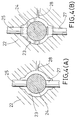
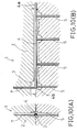
- the pipe casting apparatus shown in FIGS. 10(A) and 10(B), is for casting a fuel delivery pipe which is mounted on an engine.
- the apparatus 1 has a die 2 defining a cavity 3, in which a center pin 4 for forming an axially elongate hole is set such that it is positioned in the longitudinal direction.
- Four movable mandrel pins 5 for forming injector mounting holes are held in radial (i.e., sidewise) contact with the center pin 4 on one side thereof.
- a stationary core pin 7 for forming a pressure regulator mounting hole is held in contact with the center pin 4 on the side thereof opposite the movable mandrel pins 5.
- the center pin 4 has its stem portion 4a cantilever supported in the die 2 such that its free end 4b is found in the cavity, so that it forms a blind hole in the cast product. A front end of the hole in a cast product is closed. In other words, the center pin 4 cannot be supported by two-point support in the die 2 because of its purpose of forming a blind hole closed at the front end. In place of two-point support, its free end 4b is supported such that it is radially clamped between one movable mandrel pin 5 and the stationary core pin 7. Its intermediate portions are supported radially on one side by the other movable mandrel pins 5.
- the center pin 4 is not deviated in position or deformed by the impact exerted to the center pin 4 by pressure pouring of molten metal under high pressure into the cavity 3.
- the fuel passage (i.e., blind hole) in the fuel delivery pipe thus can be formed with high accuracy.
- the center pin 4 is supported by the movable. mandrel pins 5 and stationary core pin 7.
- the free end 4b of the center pin 4 can no longer be radially clamped between the two pins 5 and 7.
- JP-A-61-1461 discloses a casting method in which a sliding pin is retracted after molten metal in the die cavity has solidified around the pin to allow the metal to shrink freely into the space left by retraction of the pin.
- An object of the invention is to permit satisfactory support of the center pin even in the case of a pipe having no hole crossing an axial blind hole.
- One aspect of the invention features a method of casting a pipe having an axially elongate hole of which a front end is closed, in accordance with Claim 1.
- the center pin is supported sidewise by the support pin in the cavity when molten metal is poured thereinto.
- the center pin thus is not deviated or deformed by shocks exerted thereto with the charging of molten metal. It is thus possible to form the blind hole with high accuracy.
- Once molten metal has been charged into the cavity no shock due to molten metal is exerted to the center pin, so that deviation or the like of the center pin is not caused even if the support pin is separated from the center pin.
- the support pin is separated from the center pin after the charging of molten metal, and the space formed as a result of the separation of the support pin from the center pin is replenished with molten metal and is thus closed. In this way, it is possible even in the case of a pipe having no hole crossing an axial blind hole to charge molten metal with the center pin supported satisfactorily with the support pin and form no sidewise hole open to the closed end portion of the blind hole.
- the invention can be carried out using an apparatus for casting a pipe having an axially elongate hole closed at one end.
- the apparatus comprises a rod-like center pin for forming the blind hole, the center pin being positioned in a cavity of a die in a predetermined positional relation thereto such that a stem portion of the center pin is cantilever supported in the die and the free end of the center pin is found in the cavity, a support pin for supporting the center pin sldewise to prevent positional deviation of the center pin, a support pin retracting mechanism for retracting the support pin apart from the center pin by a predetermined distance after the die cavity has been filled with molten metal, and a molten metal replenishing mechanism for replenishing with molten metal a space formed as a result of the retraction of the support pin by the support pin retracting mechanism after the cavity has been filled with molten metal.
- molten metal is charged into the die cavity with the center pin held supported sidewise by the support pin, so that a blind hole can be formed with high accuracy without possibility of deviation or the like of the center pin which may otherwise be caused due to shocks exerted thereto during pressure charging of molten metal.
- the support pin is retracted apart from the center pin by the support pin retracting mechanism in the state that the cavity is filled with molten metal and also the space formed by the retraction of the support pin is replenished with molten metal by the molten metal replenishing mechanism, so that the hole that has initially been formed by the support pin is closed.
- the molten metal replenishing mechanism can be adapted to replenish the space formed by the retraction of the support pin with molten metal by pressurizing the molten metal in the cavity with a pressurizing pin. In this mode of operation, no molten metal has to be replenished through a gate, and it is thus possible to obtain efficient replenishment of the space formed by the retraction of the support pin with molten metal even where the support pin and the gate are spaced apart a large distance.
- the support pin and the pressurizing pin are preferably interlocked to each other.
- This mode of operation requires only single set of means for driving the support pin and the pressurizing pin, and thus permits reduction of the installation cost.
- the pressurizing pin is pushed into the cavity simultaneously with the retraction of the support pin, thus ensuring smooth replenishment with molten metal.
- the cavity has a molten metal flow groove extending from the position corresponding to the support pin to the gate as the molten metal supply part.
- This arrangement permits readier flow of molten metal from the gate to the position corresponding to the support pin, and the space formed by the retraction of the support pin can be efficiently replenished with molten metal through the gate. Efficient replenishment of molten metal is thus obtainable even in the case where it is impossible to provide a gate near the support pin.
- FIGS. 1(A) to 1(C) are sectional views showing successive steps in the pipe casting method.
- FIGS. 2(A) and 2(B) are fragmentary sectional views showing the pipe casting apparatus.
- FIG. 3 is a plan view showing a pipe product W obtained by the casting.
- the pipe product W obtained by the casting in the pipe casting method according to this embodiment is a fuel delivery pipe for supplying fuel to an engine.
- the pipe product W has an axial fuel passage wd having an inner closed end we.
- the axial fuel passage wd is an axial blind hole closed at the inner end.
- the pipe product W also has four injector mounting holes wj for mounting injectors therein, the injector mounting holes wj communicating with the fuel passage wd.
- the pipe casting apparatus 10 for forming the delivery pipe w comprises a die 12.
- a cavity 13 is defined therein for forming the outer shape of the delivery pipe W.
- a center pin 14 for forming the fuel passage wd is positioned in the cavity.
- the center pin 14 extends longitudinally of the cavity in a predetermined positional relation to cavity defining surfaces.
- the center pin 14 is positioned such that its stem portion 14a is cantilever supported in the die 12 and that its free end 14b is found in the cavity 14.
- Four movable mandrel pins 15 for forming the respective injector mounting holes wj are held in contact with the center pin 14 radially (i.e., sidewise) on one side thereof.
- a counter support pin 17 is held in contact with the center pin 14 at a position thereof corresponding to the movable core pin 15 adjacent the free end 14b of the center pin 14 on the side thereof opposite that movable mandrel pin 15.
- the free end 14b of the center pin 14 is thus held radially clamped between the movable mandrel pin 15 noted above and the counter support pin 17.
- the center pin 14 supported in this way thus is not deviated or bent by shocks exerted by the flow of molten metal charged into the cavity 13.
- the movable core pins 15 and counter support pin 17 serve as support pins according to the invention.
- a gate 18 through which molten metal is poured into the cavity 13, is provided near a boss space 13b of the cavity 13 for the counter support pin 17 (see FIG. 2(A)).
- the counter support pin 17 can be retracted from its position shown in FIGS. 2(A) and 2(B) to the cavity defining surface position by the action of a support pin retracting mechanism (not shown). After the lapse of a predetermined period of time, the counter support pin 17 having been retracted to the cavity defining surface position, is advanced again into the cavity 13 to locally pressurize molten metal.
- the timing of the charging of molten metal into the cavity 13 and the timing of the local pressurization of the molten metal are suitably determined according to the variable molten metal pressure which is measured by a pressure sensor (not shown) mounted on the counter support pin 17.
- the timings of the charging of molten metal and the local pressurization thereof may be determined by using a timer with reference to the instant of the end of the charging of molten metal.
- the die 12 is closed to position the center pin 14 for forming the fuel passage wd in a predetermined positional relation to the cavity defining surfaces.
- the four movable mandrel pins 15 for forming the respective injector mounting holes wj are held in contact with the positioned center pin 14 radially on one side thereof.
- the counter support pin 17 is further held in contact with the center pin 14 radially on the side thereof opposite the movable mandrel pins 15.
- the free end 14b of the center pin 14 is thus held clamped radially between the movable mandrel pin 15 and counter support pin 17 as shown in FIG. 1(A).
- molten metal is poured form a sleeve (not shown) through the gate 18 into the cavity 13.
- the completion of charging of molten metal into the cavity 13 is detected by a pressure sensor mounted on the counter support pin 17.
- the counter support pin 17 is retracted from its position in contact with the center pin 14 to the cavity defining surface position as shown in FIG. 1(B).
- molten metal is supplied through the gate 18 to the space formed by the retraction of the counter support pin 17, thus closing the hole that has been formed by the counter support pin 17. Since the gate 18 is provided near the counter support pin 17, molten metal is supplied smoothly through the gate 18 to the space noted above.
- the sleeve and gate 18 noted above constitute a molten metal replenishing mechanism for use in performing the method according to the invention.
- the counter support pin 17 is advanced to locally pressurize the molten metal in the cavity 13 when a predetermined value is measured by the pressure sensor mounted on the counter support pin 17.
- the die 12 is opened, and the delivery pipe w thus formed is taken out from the die 12. From the delivery pipe w thus taken out, the center pin 14 and the movable mandrel pins 15 are taken out, thus obtaining the pipe with the axial blind hole and holes extending across the blind hole.
- the free end of the center pin 14 is supported such that it is radially clamped between the movable mandrel pin 15 and counter support pin 17 when molten metal is poured into the cavity 13, so that the center pin 14 is neither bent nor deviated irrespective of application of shocks to the center pin 14 due to the flow of molten metal. It is thus possible to form the fuel passage wd with high accuracy.
- the center pin 14 is not deviated when the counter support pin 17 is retracted apart from the center pin 14, because the retraction of the counter support pin 17 is caused after the charging of molten metal into the cavity 14, that is, when no shock due to molten metal flow is exerted to the center pin 14 any more.
- the space that is formed by the retraction of the counter support pin 17 contains no air, that is, no air is trapped in the molten metal supplied to this space. Moreover, since the molten metal supplied to the space formed by the retraction of the counter support pin 17 is locally pressurized by the counter support pie 17 while it is solidified, the quality of this portion of the pipe is improved.
- FIGS. 4(A) and 4(B) are sectional views showing another pipe casting apparatus for performing a method according to the invention.
- the free end of a center pin 24 can be supported such that it is radially clamped between two counter support pins 25 and 27.
- a center pin 24 for forming the fuel passage w is positioned in a predetermined positional relation to the cavity defining surfaces.
- movable mandrel pins (not shown) for forming injector mounting pins wj are held in contact with the positioned center pin 24 radially on one side thereof, while also the free end of the center pin 24 is clamped radially between the two counter support pins 25 and 27, as shown in FIG. 4(A).
- molten metal is injected from a sleeve (not shown) and poured through a gate 28 into a cavity 23.
- the counter support pins 25 and 27 are retracted from their position in contact with the center pin 24 to the cavity defining surface position as shown in FIG. 4(B). With the retraction of the counter support pins 25 and 27, spaces are formed, and molten metal is supplied thereto through the gate 28, thus closing the holes having been formed by the two counter support pins 25 and 27.
- the center pin 24 can be reliably supported by using the counter support pins 25 and 27 even in the case of a delivery pipe w without any hole crossing the axial blind hole at the closed end thereof.
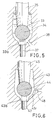
- Fig. 5 is a sectional view showing a further pipe casting apparatus for performing a method according to the invention.
- a cavity 33 has a gate 38 which is provided in the close vicinity of a boss space 33b for the counter support pin. Molten metal is thus supplied efficiently through the gate 38 to the space formed as a result of retraction of the counter support pin 37.
- Fig. 6 is a sectional view showing a further pipe casting apparatus for performing a method according to the invention.
- a cavity 43 is formed with a molten metal flow groove 43r extending between a boss space 43b for the counter support pin and a gate 48.
- Molten metal thus can be supplied efficiently through the gate 48 to the space formed by the retraction of the counter support pin 47 even in the case where it is impossible to provide the gate 48 in the close vicinity of the counter support pin boss space 43b.
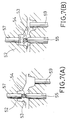
- FIGS. 7(A) and 7(B) are sectional views showing a further pipe casting apparatus for performing a method according to the invention.
- molten metal can be supplied by a pressurizing pin 59 to the space formed by the retraction of the counter support pin 57.
- a center pin 54 for forming a fuel passage wd is positioned in a predetermined positional relation to the cavity defining surfaces.
- movable mandrel pins 55 for forming an injector mounting pin wj are held in contact with the positioned center pin 54 radially on one side thereof.
- a counter support pin 57 is held in contact with a free end portion of the center pin 54 on the side thereof opposite a corresponding one of the movable mandrel pins 55. The free end portion of the center pin 54 is thus supported such that it is held clamped radially between the movable mandrel pin 55 and the counter support pin 57, as shown in FIG. 7(A).
- molten metal is injected from a sleeve (not shown) and poured through a gate into a cavity 53.
- the counter support pin 57 is retracted from its position in contact with the center pin 54 to the cavity defining surface position as shown in FIG. 7(B).
- a pressurizing pin 59 is pushed into the cavity 56 to pressurize molten metal. The molten metal is thus supplied to the space formed by the retraction of the counter support pin 57.
- molten metal need not be supplied through the gate to the space noted above. Molten metal thus can be efficiently supplied to the space formed by the removal of the counter support pin 57 even in the case where the counter support pin 57 and the gate are spaced apart a great distance. The method is thus effective even in the case where it is impossible in terms of the equipment aspect to provide the gate near the counter support pin 57.
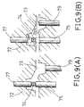
- FIGS. 8(A) and 8(B) are sectional views showing a further pipe casting apparatus for performing a method according to the invention.
- the cylinder 69y for operating the counter support pin 67 and the pressurizing pin 69 in an interlocked relation to each other, is mounted in a die 62 of the casting apparatus.
- the cylinder 69y can directly drive the pressurizing pin 69.
- a link bar 61 is coupled at one end by a pin 69p and a slot 61n to a piston rod 69r of the cylinder 69y, and the link bar 61 has a central portion rotatably supported by a pin 62p on the die 62, and is coupled at the other end also by a pin 69p and a slot 61n to a stem portion of the counter support pin 67.
- the center pin 64 for forming the fuel passage wd is positioned with respect to a cavity defining surface.
- the counter support pin 67 is brought into contact with a free end portion of the positioned center pin 64 on the side thereof opposite the cavity defining surface noted above, i.e., from above.
- the free end portion of the center pin 64 is thus supported such that it is clamped radially between the cavity defining surface and the counter support pin 67, as shown in FIG. 8(A).
- molten metal is injected from a sleeve (not shown) and poured through a gate into a cavity 63.
- the cylinder 69y is moved to lower the pressurizing pin 69.
- the molten metal is thus locally pressurized.
- the lowering of the pressurizing pin 69 by the cylinder 69y also causes rotation of the link bar 61 in the counterclockwise direction as viewed in the drawing about the pin 62p to raise the counter support pin 67 up to the vicinity of the cavity defining surface. With the rising of the counter support pin 67, a space is defined, to which molten metal having been pressurized by the pressurizing pin 69 is supplied.
- the counter support pin 67 and the pressurizing pin 69 can be operated by a single cylinder 69y, so that the equipment cost can be reduced. Simultaneously with the raising of the counter support pin 67, the pressurizing pin 69 is pushed into the cavity 63 to ensure smooth charging of molten metal.
- FIGS. 9(A) and 9(B) are sectional views showing a further pipe casting apparatus for performing a method according to the invention.
- a free end portion of a center pin 74 is held clamped radially by two counter support pins 75 and 77 and, as shown in FIG. 9(B), molten metal can be supplied by a pressurizing pin 79 to spaces formed by the retreat of the counter support pins 75 and 77.
- the center pin 74 thus can be reliably supported by using the counter support pins 75 and 77 even in the case of a delivery pipe w without any hole crossing an axial blind hole at the closed end thereof.
- the spaces formed by the retraction of the counter support pins 75 and 77 can be efficiently replenished with molten metal by the pressurizing pin 79 even in the case where the counter support pins 75 and 77 are spaced apart from the gate by a great distance.
- the center pin can be reliably supported by using support pins even in the case of a pipe having no hole crossing an axial blind hole at the closed end thereof.
Landscapes
- Engineering & Computer Science (AREA)
- Mechanical Engineering (AREA)
- Chemical & Material Sciences (AREA)
- Combustion & Propulsion (AREA)
- General Engineering & Computer Science (AREA)
- Molds, Cores, And Manufacturing Methods Thereof (AREA)
- Fuel-Injection Apparatus (AREA)
Claims (4)
- Verfahren zum Gießen eines Rohrs mit einem axial langgezogenen Loch, dessen vorderes Ende geschlossen ist, mit den folgenden Schritten:Positionieren eines stabförmigen Mittenstifts zur Ausbildung des Loches in einem Hohlraum einer Form in einer vorbestimmten Lagebeziehung dazu derart, daß ein Stielabschnitt des Mittenstifts in der Form auskragend gestützt ist und sich ein freies Ende des Mittenstifts in dem Hohlraum befindet;seitliches Stützen des positionierten Mittenstifts mit einem Stützstift zur Verhinderung einer Positionsabweichung des Mittenstifts;Einfüllen von geschmolzenem Metall in den Formhohlraum;Zurückziehen des Stützstifts weg von dem Mittenstift, bevor das eingefüllte geschmolzene Metall erstarrt; undWiederauffüllen eines durch das Zurückziehen des Stützstifts ausgebildeten Raums mit geschmolzenem Metall, bevor das eingefüllte geschmolzene Metall erstarrt.
- Verfahren nach Anspruch 1, wobei der Wiederauffüllmechanismus für geschmolzenes Metall den als eine Folge des Zurückziehens des Stützstifts ausgebildeten Raum wiederauffüllt, indem das geschmolzene Metall in dem Hohlraum mit einem Druckstift unter Druck gesetzt wird.
- Verfahren nach Anspruch 2, wobei der Stützstift und der Druckstift miteinander verblockt sind.
- Verfahren nach Anspruch 1, wobei die Form eine Fließnut für geschmolzenes Metall hat, die sich von der Position des Stützstifts zu einem Versorgungsanguß für geschmolzenes Metall erstreckt.
Applications Claiming Priority (3)
| Application Number | Priority Date | Filing Date | Title |
|---|---|---|---|
| JP22194595A JP3183114B2 (ja) | 1995-08-30 | 1995-08-30 | 中空管の鋳造方法及びその装置 |
| JP221945/95 | 1995-08-30 | ||
| JP22194595 | 1995-08-30 |
Publications (2)
| Publication Number | Publication Date |
|---|---|
| EP0761346A1 EP0761346A1 (de) | 1997-03-12 |
| EP0761346B1 true EP0761346B1 (de) | 1999-10-20 |
Family
ID=16774624
Family Applications (1)
| Application Number | Title | Priority Date | Filing Date |
|---|---|---|---|
| EP96305886A Expired - Lifetime EP0761346B1 (de) | 1995-08-30 | 1996-08-12 | Verfahren zur Herstellung eines Rohres im Spritzguss |
Country Status (5)
| Country | Link |
|---|---|
| US (1) | US5711364A (de) |
| EP (1) | EP0761346B1 (de) |
| JP (1) | JP3183114B2 (de) |
| KR (1) | KR100205118B1 (de) |
| DE (1) | DE69604750T2 (de) |
Families Citing this family (9)
| Publication number | Priority date | Publication date | Assignee | Title |
|---|---|---|---|---|
| JP3211767B2 (ja) | 1998-03-27 | 2001-09-25 | 日本電気株式会社 | 半導体装置の製造方法 |
| US6454880B1 (en) | 1999-09-29 | 2002-09-24 | Herbert (Lonny) A. Rickman, Jr. | Material for die casting tooling components, method for making same, and tooling components made from the material and process |
| DE10247524B4 (de) * | 2002-10-11 | 2004-08-12 | Siemens Ag | Kraftstoffverteiler |
| JP2007130643A (ja) * | 2005-11-08 | 2007-05-31 | Aisin Aw Co Ltd | 突出部を有する鋳造製品 |
| DE102010011003B4 (de) * | 2010-03-11 | 2011-12-08 | Audi Ag | Verfahren zur Herstellung eines Gussteils und Gießwerkzeug |
| KR101601503B1 (ko) * | 2014-10-14 | 2016-03-09 | 현대자동차주식회사 | 파이프 내 용탕 혼입 방지 기능을 갖는 코어핀 및 이를 이용한 주조장치 |
| CN106890974A (zh) * | 2017-03-21 | 2017-06-27 | 珠海市润星泰电器有限公司 | 一种半固态压铸模具 |
| KR102310239B1 (ko) | 2020-03-12 | 2021-10-08 | 큰나라찬사회적협동조합 | 공기주입형 다목적 교반장치 |
| JP7472752B2 (ja) * | 2020-10-05 | 2024-04-23 | マツダ株式会社 | 鋳造装置 |
Family Cites Families (9)
| Publication number | Priority date | Publication date | Assignee | Title |
|---|---|---|---|---|
| AT314111B (de) * | 1969-10-09 | 1974-03-25 | Rupert Fertinger Metall Und Ei | Verfahren und Vorformling zum Gießen, insbesondere Spritzgießen von Formlingen aus Metall |
| DE2402337A1 (de) * | 1974-01-18 | 1975-07-31 | Schmidt Gmbh Karl | Verfahren zur herstellung eines leichtmetallkolbens mit einem in seinem kopfteil angeordneten ringfoermigen kuehlkanal |
| CA1089166A (en) * | 1977-07-05 | 1980-11-11 | Remi Frenette | Threading device |
| JPS611461A (ja) * | 1984-06-13 | 1986-01-07 | Taiho Kogyo Co Ltd | 鋳造方法 |
| JPS619959A (ja) * | 1984-06-27 | 1986-01-17 | Honda Motor Co Ltd | 中空軸の鋳造方法 |
| JPH0611461A (ja) * | 1992-06-25 | 1994-01-21 | Kanai Hiroyuki | 平鋼線の疵検査方法 |
| JP3223728B2 (ja) * | 1993-12-24 | 2001-10-29 | トヨタ自動車株式会社 | 横孔付管の鋳造方法と鋳造品 |
| KR950016995A (ko) * | 1993-12-15 | 1995-07-20 | 와다 아끼히로 | 가로구멍 부착관의 주조방법과 이를 위한 주형 및 얻어지는 주조품 |
| DE9413450U1 (de) * | 1994-08-19 | 1994-10-20 | Gießerei Erlau GmbH, 98553 Erlau | Druckgußwerkzeug |
-
1995
- 1995-08-30 JP JP22194595A patent/JP3183114B2/ja not_active Expired - Fee Related
-
1996
- 1996-08-12 EP EP96305886A patent/EP0761346B1/de not_active Expired - Lifetime
- 1996-08-12 DE DE69604750T patent/DE69604750T2/de not_active Expired - Fee Related
- 1996-08-13 US US08/696,059 patent/US5711364A/en not_active Expired - Fee Related
- 1996-08-29 KR KR1019960036445A patent/KR100205118B1/ko not_active Expired - Fee Related
Also Published As
| Publication number | Publication date |
|---|---|
| DE69604750T2 (de) | 2000-04-27 |
| US5711364A (en) | 1998-01-27 |
| JP3183114B2 (ja) | 2001-07-03 |
| EP0761346A1 (de) | 1997-03-12 |
| DE69604750D1 (de) | 1999-11-25 |
| JPH0957421A (ja) | 1997-03-04 |
| KR100205118B1 (ko) | 1999-07-01 |
Similar Documents
| Publication | Publication Date | Title |
|---|---|---|
| EP0761346B1 (de) | Verfahren zur Herstellung eines Rohres im Spritzguss | |
| US5538413A (en) | Apparatus for strengthening weld lines in molded parts | |
| KR910009623B1 (ko) | 주조장치용의 가압장치 | |
| JPS59100236A (ja) | 繊維強化複合部材の製造方法 | |
| US7806162B2 (en) | Controlled pressure casting | |
| EP0496842A4 (de) | ||
| JP2007260687A (ja) | シリンダブロックの半溶融成形方法および半溶融成形装置 | |
| JPS61144257A (ja) | 鋳造方法 | |
| CA2138102C (en) | Process for casting pipe with transversal holes, casting die for the same and casting product obtainable by the same | |
| US5732761A (en) | Shell mold for casting a cylindrical product, apparatus for molding the shell mold, and casting method using the shell mold | |
| EP0486673A4 (de) | ||
| CA1334615C (en) | Die member for forming a lost foam pattern | |
| JPH0531564A (ja) | 局部スクイズ鋳造におけるスクイズピンの加圧タイミング制御方法 | |
| US6935221B2 (en) | Method for manufacturing an aluminum die cast piston for reciprocating compressors | |
| JPS61150746A (ja) | シリンダブロツク素材用鋳型 | |
| JPS5913941B2 (ja) | 横型締,竪鋳込型ダイカスト法および装置 | |
| EP0834365A1 (de) | Druckgiessform zur Herstellung faserverstärkter Artikel | |
| JPH04339556A (ja) | 筒状インサート保持装置 | |
| JPS61154753A (ja) | 水ジヤケット用砂中子の支持構造 | |
| EP0815988B1 (de) | Verfahren und Vorrichtung zum Einpressen von Einzelteilen in Gussstücke | |
| EP0819485B1 (de) | Verfahren, Vorrichtung und Feingiessform zum Giessen zylindrischer Gegenstände | |
| JPS61180665A (ja) | サイアミ−ズ型シリンダブロツクの製造方法 | |
| JPS61147960A (ja) | サイアミ−ズ型シリンダブロツク素材の鋳造方法 | |
| JPH04111955A (ja) | V型シリンダーブロックのダイカスト金型 | |
| JPS6132729A (ja) | 中空成形品の製造方法および装置 |
Legal Events
| Date | Code | Title | Description |
|---|---|---|---|
| PUAI | Public reference made under article 153(3) epc to a published international application that has entered the european phase |
Free format text: ORIGINAL CODE: 0009012 |
|
| 17P | Request for examination filed |
Effective date: 19960821 |
|
| AK | Designated contracting states |
Kind code of ref document: A1 Designated state(s): DE FR GB IT |
|
| 17Q | First examination report despatched |
Effective date: 19971223 |
|
| GRAG | Despatch of communication of intention to grant |
Free format text: ORIGINAL CODE: EPIDOS AGRA |
|
| GRAG | Despatch of communication of intention to grant |
Free format text: ORIGINAL CODE: EPIDOS AGRA |
|
| GRAH | Despatch of communication of intention to grant a patent |
Free format text: ORIGINAL CODE: EPIDOS IGRA |
|
| GRAH | Despatch of communication of intention to grant a patent |
Free format text: ORIGINAL CODE: EPIDOS IGRA |
|
| GRAA | (expected) grant |
Free format text: ORIGINAL CODE: 0009210 |
|
| AK | Designated contracting states |
Kind code of ref document: B1 Designated state(s): DE FR GB IT |
|
| ET | Fr: translation filed | ||
| REF | Corresponds to: |
Ref document number: 69604750 Country of ref document: DE Date of ref document: 19991125 |
|
| ITF | It: translation for a ep patent filed | ||
| PLBE | No opposition filed within time limit |
Free format text: ORIGINAL CODE: 0009261 |
|
| STAA | Information on the status of an ep patent application or granted ep patent |
Free format text: STATUS: NO OPPOSITION FILED WITHIN TIME LIMIT |
|
| 26N | No opposition filed | ||
| REG | Reference to a national code |
Ref country code: GB Ref legal event code: IF02 |
|
| PGFP | Annual fee paid to national office [announced via postgrant information from national office to epo] |
Ref country code: FR Payment date: 20040810 Year of fee payment: 9 |
|
| PGFP | Annual fee paid to national office [announced via postgrant information from national office to epo] |
Ref country code: GB Payment date: 20040811 Year of fee payment: 9 |
|
| PGFP | Annual fee paid to national office [announced via postgrant information from national office to epo] |
Ref country code: DE Payment date: 20040819 Year of fee payment: 9 |
|
| REG | Reference to a national code |
Ref country code: GB Ref legal event code: 746 Effective date: 20041018 |
|
| PG25 | Lapsed in a contracting state [announced via postgrant information from national office to epo] |
Ref country code: IT Free format text: LAPSE BECAUSE OF NON-PAYMENT OF DUE FEES;WARNING: LAPSES OF ITALIAN PATENTS WITH EFFECTIVE DATE BEFORE 2007 MAY HAVE OCCURRED AT ANY TIME BEFORE 2007. THE CORRECT EFFECTIVE DATE MAY BE DIFFERENT FROM THE ONE RECORDED. Effective date: 20050812 Ref country code: GB Free format text: LAPSE BECAUSE OF NON-PAYMENT OF DUE FEES Effective date: 20050812 |
|
| REG | Reference to a national code |
Ref country code: FR Ref legal event code: D6 |
|
| PG25 | Lapsed in a contracting state [announced via postgrant information from national office to epo] |
Ref country code: DE Free format text: LAPSE BECAUSE OF NON-PAYMENT OF DUE FEES Effective date: 20060301 |
|
| GBPC | Gb: european patent ceased through non-payment of renewal fee |
Effective date: 20050812 |
|
| PG25 | Lapsed in a contracting state [announced via postgrant information from national office to epo] |
Ref country code: FR Free format text: LAPSE BECAUSE OF NON-PAYMENT OF DUE FEES Effective date: 20060428 |
|
| REG | Reference to a national code |
Ref country code: FR Ref legal event code: ST Effective date: 20060428 |