EP0761339B1 - Appareil à étages multiples pour fabriquer des roues dentées par laminage - Google Patents
Appareil à étages multiples pour fabriquer des roues dentées par laminage Download PDFInfo
- Publication number
- EP0761339B1 EP0761339B1 EP96113866A EP96113866A EP0761339B1 EP 0761339 B1 EP0761339 B1 EP 0761339B1 EP 96113866 A EP96113866 A EP 96113866A EP 96113866 A EP96113866 A EP 96113866A EP 0761339 B1 EP0761339 B1 EP 0761339B1
- Authority
- EP
- European Patent Office
- Prior art keywords
- roller die
- roller
- workpiece
- rolling
- roughing
- Prior art date
- Legal status (The legal status is an assumption and is not a legal conclusion. Google has not performed a legal analysis and makes no representation as to the accuracy of the status listed.)
- Expired - Lifetime
Links
- 238000005096 rolling process Methods 0.000 title claims description 138
- 230000001360 synchronised effect Effects 0.000 claims description 19
- 230000007423 decrease Effects 0.000 claims description 4
- 238000000034 method Methods 0.000 description 18
- 230000007246 mechanism Effects 0.000 description 12
- 238000010438 heat treatment Methods 0.000 description 9
- 238000011282 treatment Methods 0.000 description 6
- 230000004075 alteration Effects 0.000 description 4
- 239000003638 chemical reducing agent Substances 0.000 description 4
- 238000010276 construction Methods 0.000 description 4
- 230000013011 mating Effects 0.000 description 4
- 239000006185 dispersion Substances 0.000 description 3
- 238000002474 experimental method Methods 0.000 description 3
- 230000006872 improvement Effects 0.000 description 3
- 239000010687 lubricating oil Substances 0.000 description 3
- 238000003825 pressing Methods 0.000 description 3
- OKTJSMMVPCPJKN-UHFFFAOYSA-N Carbon Chemical compound [C] OKTJSMMVPCPJKN-UHFFFAOYSA-N 0.000 description 2
- 238000005520 cutting process Methods 0.000 description 2
- 230000003247 decreasing effect Effects 0.000 description 2
- 230000000694 effects Effects 0.000 description 2
- 238000005098 hot rolling Methods 0.000 description 2
- 238000004519 manufacturing process Methods 0.000 description 2
- 239000000463 material Substances 0.000 description 2
- 239000003921 oil Substances 0.000 description 2
- 230000002250 progressing effect Effects 0.000 description 2
- 238000004513 sizing Methods 0.000 description 2
- 229910000975 Carbon steel Inorganic materials 0.000 description 1
- 206010016275 Fear Diseases 0.000 description 1
- 239000010953 base metal Substances 0.000 description 1
- 238000005452 bending Methods 0.000 description 1
- 239000010962 carbon steel Substances 0.000 description 1
- 210000000078 claw Anatomy 0.000 description 1
- 230000006835 compression Effects 0.000 description 1
- 238000007906 compression Methods 0.000 description 1
- 238000007865 diluting Methods 0.000 description 1
- 238000009826 distribution Methods 0.000 description 1
- 229910002804 graphite Inorganic materials 0.000 description 1
- 239000010439 graphite Substances 0.000 description 1
- 230000006698 induction Effects 0.000 description 1
- 239000000314 lubricant Substances 0.000 description 1
- 239000000843 powder Substances 0.000 description 1
- 230000005855 radiation Effects 0.000 description 1
- 230000003014 reinforcing effect Effects 0.000 description 1
- 102200094897 rs121913558 Human genes 0.000 description 1
- 230000008719 thickening Effects 0.000 description 1
- XLYOFNOQVPJJNP-UHFFFAOYSA-N water Substances O XLYOFNOQVPJJNP-UHFFFAOYSA-N 0.000 description 1
Images



Classifications
-
- B—PERFORMING OPERATIONS; TRANSPORTING
- B21—MECHANICAL METAL-WORKING WITHOUT ESSENTIALLY REMOVING MATERIAL; PUNCHING METAL
- B21H—MAKING PARTICULAR METAL OBJECTS BY ROLLING, e.g. SCREWS, WHEELS, RINGS, BARRELS, BALLS
- B21H5/00—Making gear wheels, racks, spline shafts or worms
- B21H5/02—Making gear wheels, racks, spline shafts or worms with cylindrical outline, e.g. by means of die rolls
-
- B—PERFORMING OPERATIONS; TRANSPORTING
- B21—MECHANICAL METAL-WORKING WITHOUT ESSENTIALLY REMOVING MATERIAL; PUNCHING METAL
- B21H—MAKING PARTICULAR METAL OBJECTS BY ROLLING, e.g. SCREWS, WHEELS, RINGS, BARRELS, BALLS
- B21H5/00—Making gear wheels, racks, spline shafts or worms
- B21H5/02—Making gear wheels, racks, spline shafts or worms with cylindrical outline, e.g. by means of die rolls
- B21H5/022—Finishing gear teeth with cylindrical outline, e.g. burnishing
Definitions
- the present invention relates to a multistage gear-rolling apparatus. For instance, it is applicable to production of vehicle-flywheels having teeth and gears used in driving systems.
- gears have been produced by way of a hob-cutting step and a shaving finish-step with respect to a disk-shaped workpiece.
- a hob-cutting step and a shaving finish-step with respect to a disk-shaped workpiece.
- a shaving finish-step with respect to a disk-shaped workpiece.
- a finishing rolling method apparatus has been disclosed in Japanese Unexamined Patent Publication (KOKAI) No.54-62,148.
- a set of rollers 203 having the first forming teeth 201 and the second forming teeth 202 disposed coaxially and longitudinally in series, are used.
- the first forming teeth 201 of the roller 203 are used for finish-rolling a first teeth portion 101 of a workpiece 100
- the second forming teeth 202 of the roller 203 are used for finish-rolling a second teeth portion 102 of the workpiece 100.
- the first forming teeth 201 of the roller 203 are squeezed in the direction of the arrow "A1", and thereby the first teeth portion 101 are finish-rolled. Thereafter, the first forming teeth 201 are withdrawn in the direction of the arrow "A2".
- the workpiece 100 is relatively moved in the direction of the arrow "B1", that is, the axial direction.
- the second forming teeth 202 of the roller 203 are squeezed in the direction of the arrow "A1", and thereby the second teeth portion 102 are finish-rolled.
- this publication gear-rolling technique requires that the workpiece 100 formed by the rough-rolling apparatus is once removed from the rough-rolling apparatus and the workpiece 100 is reset to the finish-rolling apparatus having the roller 203 after the removal. Accordingly, there might arise fears in that an axial aberration of the workpiece 100 because of resetting the workpiece 100, roundness of the rolled gear is easy to be deteriorated; thus, the above-mentioned publication gear-rolling technique is disadvantageous in improving accuracy of the rolled gear because of resetting the workpiece 100.
- first forming teeth 201 and the second forming teeth 202 are disposed coaxially and in series in the axial direction, the first forming teeth 201 are used only for finish-rolling the first teeth 101 of the workpiece 100, similarly, the second forming teeth 202 are used only for finish-rolling the second teeth 102.
- this publication technique when the first forming teeth 201 of the roller 203 begin engaging with the first teeth portion 101 of the workpiece 100 for the finish-rolling, this publication technique requires that an engaging special mechanism for engaging with the both smoothly. Similarly, when the second forming teeth 202 of the roller 203 begin engaging with the second teeth portion 102 of the workpiece 100 for the finish-rolling, this publication technique requires that an engaging special mechanism for engaging with the both smoothly.
- the present invention has been developed in view of the aforementioned circumstances. It is therefore a first object of the prime aspect of the present invention to provide a multistage gear-rolling apparatus which can carry out a finish-rolling step immediately after a rough-rolling step to be capable of abolishing a reset of workpiece so that axial aberration of a workpiece is advantageously reduced or avoided and which can contribute to improvement in accuracy of a rolled gear.
- a multistage gear-rolling apparatus comprises: a roller squeezing apparatus including at least a roughing roller die and a finishing roller die disposed coaxially and connected in series in an axial direction of the roughing roller die, the roughing roller die having a lot of forming teeth arranged in a circumferential direction for a rough-rolling step, the finishing roller die having a lot of forming teeth arranged in a circumferential direction for a finish-rolling step.
- the roughing roller die is used for carrying out a hot rough-rolling step
- the finishing roller die is used for a warm finish-rolling step.
- a multistage gear-rolling apparatus comprises:
- the finish-rolling step can be carried out immediately after the rough-rolling step. Therefore, the workpiece can be finish-rolled without the reset of wcrkpiece; thus, the axial aberration due to the reset of workpiece is reduced or avoided. Accordingly, roundness of the rolled gear is enhanced, and accurate gears are advantageously produced.
- the warm finish-rolling step can be carried out immediately after the hot rough-rolling step. Therefore, the workpiece is finish-rolled without the reset of workpiece; thus, the axial aberration due to the reset of workpiece is reduced or avoided, roundness of the rolled gear is enhanced, and thereby accurate gears are advantageously produced.
- the warm finish-rolling step can be carried out immediately after the hot rough-rolling step, a starting temperature range and a terminating temperature range of the warm finish-rolling step are kept suitably, so that the warm finish-rolling step is carried out dexterously. Hence, rectifying effect with respect to the rolled-gear in the finish-rolling step is ensured, and thereby accurate gears are advantageously produced.
- the forming teeth of the finishing roller die can be smoothly engaged with the the teeth of the rough-rolled gear because of the engagement controlling means.
- another roller die which is used for carrying out other treatments such as chamfering, marking, can preferably be disposed with the roughing roller die and the finishing roller die coaxially and in series in an axial direction of the roughing roller die.
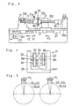
- Figure 1 is illustrates the plan view of the whole apparatus.
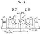
- Figure 2 illustrates the front view of the major portion of the apparatus.
- Figure 3 is the cross-sectional view of the apparatus taken along the arrow "W3-W3" of Figure 1.
- a blank holding portion 1 which operates as a workpiece holding portion, comprises a first blank holding portion 11 and a second blank holding portion 12 facing to each other.
- the first blank holding portion 11 includes a first blank holding shaft 11a having a large-diameter
- the second blank holding portion 12 includes a second holding shaft 12a having a large-diameter.
- a first motor 21 operates as a blank rotating means for operating the blank, that is, the workpiece.
- the first motor 21 drives, the first blank holding portion 11 rotates in a circumferential direction thereof (i.e., the direction of the arrow "E1" in Figure 2).
- a second motor 22 for moving the first blank holding portion 11 to transfer the blank.
- a ball screw shaft 24r rotates in a circumferential direction thereof, and thereby the first blank holding portion 11 and the blank 7 are transferred in directions of arrow "Y1" "Y2".
- a high-frequency heating coil 28 which operates as a ring-shaped heating means for heating the blank 7 by means of induction-heating.
- a thermal sensor 28c that is, a radiation pyrometer, detects situations of the heated blank.
- a roller squeezing apparatus 3 includes a first roller squeezing apparatus 31 and a second roller squeezing apparatus constituting a pair for holding the blank 7 in the radius direction of the blank 7.
- the first roller squeezing apparatus 31 comprises a first roughing roller die 32 for working as a hot rolling tool, a first finishing roller die 33 for working as a warm rolling tool, a roller die 38 for adding another treatment, such as marking or chamfering, to the blank 7, a first connecting shaft 34, and a first housing 36.
- the first connecting shaft 34 connects the first roughing roller die 32, the first finishing roller die 33, and the roller die 38 in series along the axial direction and coaxitially.
- the first roughing roller die 32, the first finishing roller die 33, and the roller die 38 are rotatably held on the first housing 36.
- the first roller squeezing apparatus 31 includes a fourth motor 24 and a first ball screw shaft 37.
- the second roller squeezing apparatus 41 comprises a second roughing roller die 42 for working as a hot rolling tool, a second finishing roller die 43 for working as a warm rolling tool, a roller die 48 for adding another treatment, such as marking or chamfering, to the blank 7, a second connecting shaft 44, and a second housing 46.
- the second connecting shaft 44 connects the second roughing roller die 42, the second finishing roller die 43, and the roller die 48 in series in the axial direction and coaxitially.
- the second roughing roller die 42, the second finishing roller die 43, and the roller die 48 are rotatably held on the second housing 46.
- the second roller squeezing apparatus 41 includes a fifth motor 25 and a second ball screw shaft 47.
- the first housing 36 is capable of squeezing the blank 7 in the direction of the arrow "X1" and is capable of withdrawing from the blank 7 in the direction of the arrow "X2".
- the second housing 46 is capable of squeezing the blank 7 in the direction of the arrow "X1” and is capable of withdrawing from the blank 7 in the directions of the arrow "X2".
- the first housing 36 having a "channel-shape" in a plan view, includes two first faced thick-wall portions 36a,36b facing each other, and a first connecting thick-wall portion 36c for connecting the first faced thick-wall portions 36a, 36b.
- the second housing 46 having a "channel-shape” in a plan view, includes two second faced thick-wall portions 46a,46b facing each other, and a second connecting thick-wall portion 46c for connecting the second faced thick-wall portions 46a, 46b.
- the first housing 36 and the second housing 46 are movable along the guiding portions 3b fixed on the base 3a for supporting themselves in the directions of the arrow "X1" "X2".
- the fourth motor 24 is driven, the driving force of the fourth motor 24 is reduced by use of the first speed reducer 24i and is transmitted to the first ball screw shaft 37. Then, the first ball screw shaft 37 is rotated in the circumferential direction, the first housing 36 is transferred in the direction of the arrow "X1"; hence, the first roughing roller die 32, the first finishing roller die 33 and the roller die 38 which are held on the first housing 36 are transferred in the same direction.
- the fourth motor 24 when the fourth motor 24 is conversely rotated, the first ball screw shaft 37 is conversely rotated in the circumferential direction thereof, and thereby the first housing 36 is transferred in the direction of the arrow "X2". Accordingly, the first roughing roller die 32, the first finishing roller die 33 and the roller die 38 are transferred together in the same direction to be withdrawn from the blank 7.
- the fourth motor 24 and the first ball screw shaft 37 operate as squeezing means for squeezing the first roughing roller die 32, the first finishing roller die 33 and the like toward the blank 7.
- the fifth motor 25 When the fifth motor 25 is conversely rotated, the second ball screw shaft 47 is conversely rotated in the circumferential direction, and thereby the second housing 46 is transferred in the direction of the arrow "X2". Accordingly, the second roughing roller die 42, the second finishing roller die 43 and roller die 48 are transferred together in the same direction to be withdrawn from the blank 7.
- the fifth motor 25 and the second ball screw shaft 47 operate as squeezing means for squeezing the second roughing roller die 42, the second finishing roller die 43 and the like toward the blank 7.
- the load working on the first housing 36 is detected by use of a first load cell 36r, and a transferred amount of the first housing 36 is detected by use of a first liner scale 36k.
- the load working on the second housing 46 is detected by use of a second load cell 46r, and a transferred amount of the second housing 46 is detected by use of a second liner scale 46k.
- Each of detected signals is inputted to a controller system 9.
- the aforementioned fourth motor 24 and fifth motor 25, constituting a servo-motor respectively, are controlled on the basis of squeezing synchronous command signals and withdrawing synchronous command signals, and thereby operating the first ball screw shaft 37 and the second ball screw shaft 47 synchronously. Accordingly, the first roughing roller die 32 and the second roughing roller die 42 can be synchronously squeezed in the direction of the arrow "X1" and can be synchronously withdrawn in the direction of the arrow "X2".
- the driving force of the motor 5 for rotating the first die is transmitted to a phase adjusting mechanism 55x, a second reducer 55, a rotating shaft 55e, and a second constant speed universal joint 56. Accordingly, the driving force of the motor 5 is transmitted to the second connecting shaft 44, the second roughing roller die 42, the second finishing roller die 43, and the roller die 48; therefore, they are rotated.
- the phase adjusting mechanism 55x is used for adjusting the circumferential phase of the forming teeth of the first roughing roller die 32 to the circumferential phase of the forming teeth of the second roughing roller die 42.
- the phase adjusting mechanism 55x has a function for canceling the phase-difference between the first roughing roller die 32 and the second roughing rolLer die 42. With the object of realizing this function, two disks 55x,55y are fixed on condition of capable of shifting their position relatively in the circumferential thereof.
- FIG. 4 shows the first roller squeezing apparatus.
- a keyway 34h is formed at the first connecting shaft 34, rotatablely held on the first housing 36, along the axial direction.
- a mating keyway 32i is formed at the inner circumferential portion of the fitting hole of the first roughing roller die 32
- a mating keyway 33i is formed at the inner circumferential portion of the fitting hole of the first finishing roller die 33
- a mating keyway 38i is formed at the inner circumferential portion of the fitting hole of the roller die 38.
- a key 34m is engaged with the mating keyways 32i, 33i, 38i and a keyway 34h formed at the first connecting shaft 34, thereby the three dies 32, 33, 38 are integrated with respect to the circumferential direction.
- the total number of the teeth in the finishing roller die 33 is as many as those of the roughing roller dies 32.
- the total number of the teeth in the finishing roller die 43 is as many as those of the roughing roller die 42.
- Figure 5 shows only part of the forming teeth 32c, 33c.
- the second roller squeezing apparatus 41 has the similar construction to the first roller squeezing apparatus 31; therefore, as can be understood from Figure 5, the aforementioned key and keyways adjust the circumferential phase of the forming die 42c of the second roughing roller die 42 to the circumferential phase of the forming teeth 43c of the second finishing roller die 43.
- a first emitting device 76 for emitting liquid-lubricant is equipped to face the portion passed a rolling area in the first roughing roller die 32.
- a second emitting device 77 for emitting liquid-lubricant containing graphite powder is equipped to face the portion passed a rolling area in the second roughing roller die 42.
- the first emitting device 76 and the second emitting device 77 are respectively separately disposed at the position being an angle of 90° apart.
- the carbon steel based blank 7 (material; JIS-STANDARD S58C ), being kept in the normal temperature range, is held on the first blank holding portion 11.
- the second motor 22 is driven to transfer the blank 7 in the direction of the arrow "Y1" and to dispose the blank 7 in the high-frequency heating coil 28.
- the motor 21 is driven to rotate the blank 7 in the circumferential direction (i.e., the direction of the arrow "E1" in Figure 2).
- the outer circumferential portion of the blank 7 is induction-heated by use of the high-frequency heating coil 28.
- the range heated up to 900°C in the blank 7 is from the outer circumferential of the blank 7 to a depth being approximately 1.3 times of the tooth height.
- the heating time is set in the neighborhood from some seconds through 30 seconds.
- the rolling step is carried out.
- the time from the termination of the heating step to the start of the hot roughing-rolling step is set within 5 seconds. The reason is that the heat-transmission into the inside of the blank 7 is suppressed to reduce the increasing of the temperature in the middle portion of the blank 7 for improving a temperature-distribution in the blank 7.
- the blank 7 is transferred in the direction of the arrow "Y1" to be disposed at a forming location "R1" in Figure 1.
- the second blank holding portion 12 is moved in the direction of the arrow "Y3"; thus, both of the second blank holding portion 12 and the first blank holding portion 11 hold the blank 7 forcibly as illustrated in Figure 3.
- the forcible force is secured to several [tonf] by use of the hydraulic cylinder 29 shown in Figure 3.
- the blank 7 is rotated in the circumferential direction thereof on the basis of the driving force of the third motor 23.
- a clutch 21p shown in Figure 3 is turned off in order not to transmit the driving force of the first motor 21 to the blank 7.
- first roughing roller die 32 and the second roughing roller die 42 are rotated at a predetermined constant speed in the range of from 150 through 300 [rpm].
- the first roughing roller die 32 and the second roughing roller die 42 are synchronously squeezed to the outer circumferential portion of the blank 7 in the direction of the arrow "X1" ( squeezing speed: 6mm/sec). After the squeezing operation, keeping the operation is carried out for approximately 4 seconds at the squeezed end.
- the deformation constituting the teeth portion and the sizing are carried out at the outer circumferential portion of the blank 7, so that the plural teeth are generated during the rolling step and the rolled gear 78 can be produced.
- the first roughing roller die 32 and the second roughing roller die 42 are synchronously withdrawn from the outer circumferential portion of the blank 7 in the direction of the arrow "X2".
- the squeezing synchronous precision between the first roughing roller die 32 and the second roughing roller die 42 is high.
- the distance between the central axis line of the blank 7 and the central axis line of the first roughing roller die 32 is indicated as L L
- the distance between the central axis line of the blank 7 and the central axis line of the second roughing roller die 42 is indicated as L R .
- L L and L R correspond with each other within the precision higher than the range from 0.03 through 0.05mm.
- a lean of the teeth-groove in the rolled gear can be decreased.
- the starting temperature can be set in the range of from 850 through 1100 °C
- the terminating temperature can be set in the range of from 500 through 700 °C.
- the cylinder 29 shown in Figure 3 and the second motor 22 transfer the blank 7 further in the direction of the arrow "Y1" to dispose the blank 7 at the finish-forming location "R2" shown in Figure 1.
- the first finishing roller die 33 being rotated with the first roughing roller die 32, is transferred in the direction of the arrow "X1" to be squeezed toward the blank 7, and the second finishing roller die 43, being rotated with the second roughing roller die 42, is transferred in the direction of the arrow "X1" to be squeezed to the blank 7 synchronously. Therefore, the teeth of the blank 7 are finish-rolled in the range of warm temperatures.
- the first finishing roller die 33 and the second finishing roller die 43 are transferred in the direction of the arrow "X2" and are withdrawn from the blank 7.
- the starting temperature can be set in the range of from 400 through 700 °C
- the terminating temperature can be set in the range of from 200 through 650 °C.
- the warm finish-rolling step is terminated as described above.
- the rolled gear 78 is transferred to the location "R3".
- a chamfering treatment or a marking treatment is carried out with respect to the rolled gear 78.
- Figure 6 shows an example of timing charts where the rolling step carried out by use of the embodiment apparatus.
- the horizontal axis in Figure 6 shows the passed time when the starting time for the hot rough-rolling step is set at "0".
- the lower part of vertical axis in Figure 6 shows advance and delay in the blank-rotation when a target rotational speed of the aforementioned blank 7 is set at N B .
- the upper part of the vertical axis shows a ratio of horsepower(h.p.) in the torque transmitting variable clutch 26. This ratio means the ratio at which the driving force of the third motor 23 is transmitted to the second holding shaft 12a of the second blank holding portion 12.
- the roughing roller dies 32, 42 are begun to be fed in the squeezing direction. From time-a, being immediately after time-a', through time-e, the hot rough-rolling step is carried out with respect to the blank 7. From time-e, the roughing roller dies 32,42 are withdrawn from the rolled gear 78 in the direction of the arrow "X2". From immediately after time-e', the finishing roller dies 33, 43 are begun to be fed in the squeezing direction ( i.e., the direction of the arrow "X1" ). At time-f, the forming teeth 33c,43c of the finishing roller dies 33,43 begin to engage with the teeth of rough-rolled gear 78.
- the number of the teeth of finishing roller dies 33, 43 is set at that of the roughing rolled dies 32, 42, namely, Z RH .
- the blank 7 is basically rotated at the target rotational speed N B except specified periods.
- the controller system 9 which operates as an engagement controlling means, controls the second holding shaft 12a of the second blank holding portion 12 in order to control the blank 7 without advance and delay with respect to the target rotational speed N B .
- the roller dies 32, 42, 33, 43 is controlled on the basis of the controller system 9 to rotate at a rotational speed "N R .
- the rotational speed of the blank 7 is gradually increased with the hot rough-rolling step progressing.
- the rotational speed of the blank 7 is increased by +0.3% with respect to the target rotational speed N B .
- the engagement between the teeth of the rolled gear 78 and the forming teeth 32c,42c of the roughing roller dies 32,42 is enhanced with the teeth of the rolled gear 78 generated, so that the rotational speed of the rolled gear 78 is increased under the influence of the rotational driving force of the roughing roller dies 32,42.
- the controller system 9 controls the transmitting torque variable clutch 26 from time-b through time-d to decrease the rate of the transmitted horsepower in the range of less than 50% and to decrease the transmitting of the driving force from the third motor 23.
- the rotational speed of the blank 7( i.e., the rolled gear 78 ) returns again to the target rotational speed N B . Therefore, the rotational speed of the blank 7 returns to the target rotational speed N B at time-d where the teeth are fitted to be a nearly steady state with the sizing operation progressing.
- the controller system 9 controls the transmitting torque variable clutch 26 in such a manner that the transmitting horsepower efficiency is returned to 100%; hence, the rotational speed of the blank 7 ( i.e., the rolled gear 78) is kept at the target rotational speed N B .
- the finishing roller dies 33,43 begin to engage with the rolled gear 78 at time-f.
- the rotational speed of the blank 7 i.e., the rough-rolled gear 78
- N B the target rotational speed of the blank 7
- the forming teeth 32c of the first roughing rolled die 32 and the forming teeth 33c of the first finishing roller die 33 agree with each other in the circumferential phase.
- the teeth 42c of the second roughing rolled die 42 and the forming teeth 43c of the second finishing roller die 43 agree with in the circumferential phase.
- the roller die 32, 33,42,43 are controlled to be rotated usually at the constant rotational speed N R on the basis of the controller system 9.
- Time-e is immediately after the termination of the hot rough-rolling step.
- the rough-rolled gear 78 is rotated at the target rotational speed N B at time-e.
- the forming teeth 42c of the roughing roller die 42, rotating at the rotational speed N R are transferred in the direction of the arrow "X2" to be withdrawn from the teeth 78c of the rolled gear 78 after the termination of the hot rough-rolling step.
- this embodiment is advantageous in improving finished accuracy and producing efficiency in the finish-rolling step
- Figure 7(C) shows time-f where the conventional engagement starts.
- the rotational speed of the rolled gear 78 varies to ( N B + ⁇ )
- the relationship immediately after the termination of the rough-rolling step can not be kept to be varied. So, the teeth 78c of the rolled gear 78 and the forming teeth 43c of the finishing roller die 43 collide with each other at the starting of engagement, and thereby the smooth engagement is hindered.
- Figure 6 shows an engaging early-region being after the start of engagement in the finish-rolling step, namely, a region from time-g through time-h, as ⁇ T2,
- the transmitting torque variable clutch 26 is controlled to reduce the ratio of the transmitting horsepower on the basis of the controller system 9.
- the rolled gear 78 is driven owing to the finishing roller dies 33,43.
- the rolled gear 78 is again rotated at the target rotational speed N B .
- the finish- rolling step is terminated at time-i.
- roller Die 38,48 for carrying out Another Treatment such as Chamfering or Marking roller Die 38,48 for carrying out Another Treatment such as Chamfering or Marking
- the target is the keeping of the phase-relationship which exists between the teeth 78c of the rolled gear 78 and the forming teeth 33c,43c of the finishing rolled dies 33, 43 in the circumferential phase and which exists immediately after the termination of the finish-rolling step.
- the controller system 9 controls the finishing roller dies 33,43, the roller dies 38,48 for chamfering or marking and the rolled gear 78 in order to rotate them.
- the roller squeezing apparatus 31, 41 are squeezed toward the rolled gear 78 to engage the forming teeth 33c,43c of the finishing roller dies 33,43 with the teeth of the rolled gear 78 smoothly.
- the first blank holding portion 11 includes a first holding shaft 11a, a operating shaft 14, a tightening body 15 having a sleeve-shape, a collet 16, a pressing body 17 having a ring-shape.
- the first holding shaft 11a having high rigidity, includes a first conical surface 11c having a reducing outer diameter as it goes to an axial end.
- the operating shaft 14 is slidablely inserted in an inserting hole lid of the first holding shaft 11a.
- the tightening body 15 is disposed at the end of the first holding shaft 11a to be engaged with a flange 14c positioned at the axial end of the operating shaft 14.
- the collet 16 operates as a engaging claw capable of moving in the direction of the arrow "C1", namely, the radius outward direction.
- the pressing body 17 is held at the end surface of the first holding shaft 11a by use of bolts( not shown).
- the second blank holding portion 12 comprises an inserting bore 18 formed at the axial end thereof and a ring-shaped pressing body 19 held with bolts (not shown) at the axial end.
- a guiding wall surface 18k with a slight inclination is formed at the inner surface of the inserting bore 18.
- the blank holding rigidity is set more rigid than 0.1 mm/tonf in the direction of the arrow "X1", namely, the squeezing direction. Concretely, from 0.01 through 0.085 mm/tonf, or from 0.07 through 0.08 mm/tonf.
- the aforementioned blank holding rigidity on the basis of the blank holding portion 1 is defined as follows:
- E B ⁇ B S (mm) / ⁇ W' (tonf) ⁇
- the squeezing synchronous precision means an average deflection in a squeezed amount of the first roller die 32 and the second roller die 42 during the rolling step when both of the roller dies are synchronously squeezed with respect to the blank 7.
- the squeezing synchronous precision L between the first roller die 32 and the second roller die 42 is set higher than 0.03 mm in the direction of the arrow "X1", namely, the squeezing direction. Concretely, it is set in the range from 0.005 through 0.03 mm. In this embodiment, not only the squeezing synchronous precision between the first roughing roller die 32 and the second roughing roller die 42, but also the squeezing synchronous precision between the first finishing roller die 33 and the second finishing roller die 43, the squeezing synchronous precision is the aforementioned same range.
- ⁇ L' means an absolute value of the difference between the a squeezed amount of the first roller die 32 and a squeezed amount of the second roller die 42 at the certain time.
- ⁇ L' is a moment value, it varies from the starting to the terminating in the rolling step; therefore, the average value of the aforementioned moment values ⁇ L' is determined as the squeezing synchronous precision ⁇ L in the present invention.
- the aforementioned ⁇ L' is under the influence of the originally feeding precision on the basis of the roller squeezing apparatus 3 in the no-load condition and a bending amount of the roller squeezing apparatus 3 during the rolling step.
- the aforementioned squeezing synchronous precision having high precision is archived as follows: As shown in Figure 1, the ball-screw system having the accurate ball screw shafts 37, 47 is employed, and the servo-controlled system operating the ball screw shafts 37,47 synchronously by way of the motors 24,25 operating as servo-motor is employed. A combination of these systems shows that the feeding precision for transferring the first roller die 32 and the second roller die 42 in the squeezing direction is improved to be high, and the rigidity of the roller squeezing apparatus 3 is high.
- the rigidity of the roller squeezing apparatus 3 is set in the region more rigid than 0.01 mm/tonf. Concretely, it is set to be in the range of from 0.033 through 0.01 mm/tonf.
- the rigidity of the roller squeezing apparatus 3 is defined as follows: As shown in Figure 9, L RSO (mm) indicates the distance from the central axial line of the blank holding portion 1 to the outer end of the roller die 42 under no-load. On the other hand, when load "F" applied to this apparatus, L RSK (mm) indicates the distance the central line of the blank holding portion 1 to the outer end of the roller die 42.
- the motor 5 constituting the servo-motor for rotating the die is controlled by use of the controller system 9, the phase adjusting mechanism 55x is employed and the constant speed universal joints 53,5 are employed, this small phase-difference can be advantageously realized.
- the phase-difference between both the dies during rolling is under influence of the sum adding an initial phase-difference ⁇ to a speed dispersion ⁇ m in the rotating mechanism.
- the initial phase-difference ⁇ existing between the first roller die 32 and the second roller die 42, will be hereinafter described as follows: It is requested before rolling that the center 32t,42r in the roller die 32,42 must be disposed on the "O L -O R " line. In spite of this request, when the center 42r of forming teeth in the second roller die 42 is shifted by ⁇ with respect to the "O L - O R " line before rolling, the angle ⁇ is defined as the initial phase-difference between the first roller die 32 and the second roller die 42.
- ⁇ R is not equal to ⁇ L in a microscopic level. Because of the influence of rotational dispersion of the rotational mechanism.
- ⁇ R ⁇ L + ⁇ m '
- ⁇ 'm is defined as an speed dispersion in the rotational mechanism.
- ⁇ 'm is a moment value at a certain time, and varies slightly during rotating. So, in this embodiment, not a moment value but an average value from the starting of the rolling to the terminating of the rolling is defined as the aforementioned ⁇ m.
- one of the teeth-groove of the forming teeth of the first roller die 32 is disposed to face with one of the teeth-groove of the forming teeth of the second roller die 42.
- the phase-difference comes to be 0°.
- a module of the target gear was set at 2.4, a helix angle was set at 30°, the number of the teeth was set at 67, a facewidth of the teeth was set at 21mm, the number of the roller dies 32, 42, 33, 43 was set at 73, a rotational speed of each roller dies 32, 42, 33, and 43 was set at 300rpm.
- the induction heating was curried out on condition of 3 kHz, 600 kW.
- liquid lubricant diluting a graphite based lubricant with water, was sprayed at the rate of 5 cc/sec.
- the rolled gears having the good accuracy in the range of from class 3 through class 4 in JIS-STANDARD, were produced in the case where the hot roughing-rolling step was carried out by use of the first roughing roller die 32 and the second roughing roller die 42 without the warm finish-rolling step.
- the warm rough-rolling step was carried out for 5 seconds on condition that a compressed amount of the teeth-surface was set at 30 micrometers and the temperature was set in the range of from 500 through 600 °C; hence, the rolled gears which have class 2 through class 3 in JIS-STANDARD and which can not be produced in the conventional gear-rolling technique, were produced.
- both of the first roller squeezing apparatus 31 and the second roller squeezing apparatus 41 are used.
- either the first roller squeezing apparatus 31 or the second roller squeezing apparatus 41 may be used on condition that the blank holding rigidity is high.
Landscapes
- Engineering & Computer Science (AREA)
- Mechanical Engineering (AREA)
- Forging (AREA)
- Press Drives And Press Lines (AREA)
Claims (19)
- Appareil multi-étagé à rouler les dentures, comprenant :
un appareil de pressage à galets incluant au moins une filière à galets d'ébauche (32) et une filière à galets de finition (33) disposées coaxialement et reliées en série dans une direction axiale de ladite filière à galets d'ébauche, ladite filière à galets d'ébauche comportant un lot de dents de formation (32c) disposées dans une direction circonférentielle pour une étape de roulage d'ébauche, ladite filière à galets de finition comportant un lot de dents de formation (33c) disposées dans une direction circonférentielle pour une étape de roulage de finition. - Appareil multi-étagé à rouler les dentures selon la revendication 1, dans lequel ledit appareil de pressage à galets inclut un premier appareil de pressage à galets (31) et un deuxième appareil de pressage à galets (41) se faisant face mutuellement de façon à maintenir la pièce de fabrication dans la direction radiale de ladite pièce de fabrication pour roulage,
la précision synchrone de pressage entre ledit premier appareil de pressage à galets et ledit deuxième appareil de pressage à galets est établie dans la plage allant de 0,005 mm à 0,03 mm. - Appareil multi-étagé à rouler les dentures selon la revendication 1, dans lequel ledit appareil de pressage à galets inclut un premier appareil de pressage à galets (31) et un deuxième appareil de pressage à galets (41) se faisant face mutuellement de façon à maintenir ladite pièce de fabrication dans la direction radiale de ladite pièce de fabrication pour roulage,ledit premier appareil de pressage à galets comprend une première filière à galets d'ébauche (32) et une première filière à galets de finition (33) reliées coaxialement et en série dans une direction axiale de ladite première filière à galets d'ébauche, etledit deuxième appareil de pressage à galets comprend une deuxième filière à galets d'ébauche (42) et une deuxième filière à galets de finition (43) reliées coaxialement et en série dans une direction axiale de ladite première filière à galets d'ébauche.
- Appareil multi-étagé à rouler les dentures selon la revendication 1, dans lequel ledit appareil de pressage à galets inclut un premier appareil de pressage à galets (31) et un deuxième appareil de pressage à galets (41) se faisant face mutuellement de façon à maintenir ladite pièce de fabrication dans la direction radiale de ladite pièce de fabrication pour roulage,ledit premier appareil de pressage à galets comprend une première filière à galets d'ébauche (32), une première filière à galets de finition (33), et une autre filière à galets reliées coaxialement et en série dans une direction axiale de ladite première filière à galets d'ébauche, etledit deuxième appareil de pressage à galets comprend une deuxième filière à galets d'ébauche (42), une deuxième filière à galets de finition (43), et encore une autre filière à galets reliées coaxialement et en série dans une direction axiale de ladite première filière à galets d'ébauche.
- Appareil multi-étagé à rouler les dentures selon l'une des revendications 1 à 4, dans lequel une différence de phase entre ladite première filière a galets d'ébauche (32) et ladite deuxième filière à galets d'ébauche (42) dans la direction circonférentielle est établie à moins de 0,1°, et
une différence de phase entre ladite première filière à galets de finition (33) et ladite deuxième filière à galets de finition (43) dans la direction circonférentielle est établie à moins de 0,1°. - Appareil multi-étagé à rouler les dentures selon l'une des revendications 1 à 5, comprenant :une partie de maintien de la pièce de fabrication pour maintenir une pièce de fabrication et incluant une première partie de maintien de la pièce de fabrication (11) et une deuxième partie de maintien de la pièce de fabrication (12) se faisant mutuellement face,dans lequel la rigidité de maintien de la pièce de fabrication de ladite partie de maintien de la pièce de fabrication est établie plus rigide que 0,1 mm/T dans la direction de pressage dudit appareil de pressage à galets.
- Appareil multi-étagé à rouler les dentures selon la revendication 6, dans lequel la rigidité de maintien de la pièce de fabrication de ladite partie de maintien de la pièce de fabrication se situe dans la plage allant de 0,01 mm/T à 0,085 mm/T dans la direction de pressage dudit appareil de pressage à galets.
- Appareil multi-étagé à rouler les dentures selon la revendication 6 ou 7, comprenant de plus :un moteur (21) pour faire tourner ladite partie de maintien de la pièce de fabrication ; etun embrayage capable de faire varier un rapport de transmission par rapport à ladite partie de maintien de la pièce de fabrication et disposé entre ledit moteur et ladite partie de maintien de la pièce de fabrication ;dans lequel ledit embrayage est commandé pour faire varier ledit rapport de transmission de sorte que ladite partie de maintien de la pièce de fabrication puisse tourner à une vitesse uniforme.
- Appareil multi-étagé à rouler les dentures selon l'une des revendications 1 à 8, dans lequel ladite filière à galets d'ébauche (32) est utilisée pour accomplir une étape de roulage d'ébauche à chaud, et ladite filière à galets de finition (33) est utilisée pour une étape de roulage de finition à tiède.
- Appareil multi-étagé à rouler les dentures, comprenant :une partie de maintien de la pièce de fabrication pour maintenir une pièce de fabrication devant être transformée en une roue d'engrenage roulée d'ébauche ;un appareil de pressage à galets capable de presser ladite pièce de fabrication et de se retirer de ladite pièce de fabrication, ledit appareil de pressage à galets incluant au moins une filière à galets d'ébauche (32) et une filière à galets de finition (33) disposées coaxialement et reliées en série dans une direction axiale de ladite filière à galets d'ébauche, ladite filière à galets d'ébauche comportant un lot de dents de formation (32c) disposées dans une direction circonférentielle pour une étape de roulage d'ébauche, ladite filière à galets de finition comportant un lot de dents de formation (33c) disposées dans une direction circonférentielle pour une étape de roulage de finition ;un moyen destiné à ajuster une phase desdites dents de formation de ladite filière de roulage d'ébauche et une phase desdites dents de formation de ladite filière à galets de finition l'une par rapport à l'autre dans une direction circonférentielle ; etun moyen destiné à commander ledit engrènement entre lesdites dents de formation de ladite filière à galets de finition et les dents de ladite roue d'engrenage roulée d'ébauche dans une direction circonférentielle, ledit moyen de commande d'engrènement visant à conserver une relation de phase circonférentielle entre lesdites dents de ladite roue d'engrenage roulée d'ébauche formée par ladite filière à galets d'ébauche et lesdites dents de formation de ladite filière à galets d'ébauche, ledit moyen de commande d'engrènement faisant tourner ladite filière à galets d'ébauche, ladite filière à galets de finition, et ladite pièce de fabrication maintenue sur ladite partie de maintien de la pièce de fabrication, presse ledit appareil de pressage à galets vers ladite roue d'engrenage roulée d'ébauche, ladite relation de phase immédiatement après ladite étape de roulage d'ébauche étant conservée, et lesdites dents de formation de ladite filière à galets de finition étant engrenées sans à-coup avec lesdites dents de ladite roue d'engrenage roulée d'ébauche.
- Appareil multi-étagé à rouler les dentures selon la revendication 10, comprenant de plus :un moteur (21) pour faire tourner ladite partie de maintien de la pièce de fabrication ; etun embrayage capable de faire varier un rapport de transmission par rapport à ladite partie de maintien de la pièce de fabrication et disposé entre ledit moteur et ladite partie de maintien de la pièce de fabrication ;dans lequel ledit moyen de commande d'engrènement commande ledit rapport de transmission dudit embrayage de sorte que ladite pièce de fabrication tourne au départ de l'engrènement entre ladite filière à galets de finition et la roue d'engrenage roulée d'ébauche à une vitesse uniforme qui est égale à une vitesse de la fin de l'étape de roulage d'ébauche.
- Appareil multi-étagé à rouler les dentures selon la revendication 11, dans lequel ledit moyen de commande d'engrènement fait décroítre ledit rapport de transmission dudit embrayage de sorte que ladite pièce de fabrication tourne à une vitesse uniforme comme une cible dans une première période de l'étape de roulage d'ébauche pour éviter que la vitesse de la pièce de fabrication augmente, de sorte que ladite pièce de fabrication tourne à une vitesse uniforme.
- Appareil multi-étagé à rouler les dentures selon la revendication 11, dans lequel ledit moyen de commande d'engrènement fait diminuer ledit rapport de transmission dudit embrayage comme une cible de sorte que ladite pièce de fabrication soit entraínée avec ladite filière à galets de finition dans une première période de ladite étape de roulage de finition pour annuler une différence de phase entre ladite filière à galets d'ébauche et ladite filière à galets de finition.
- Appareil multi-étagé à rouler les dentures selon l'une des revendications 10 à 13, dans lequel ladite filière à galets d'ébauche (32) est utilisée pour accomplir une étape de roulage d'ébauche à chaud, et ladite filière à galets de finition (33) est utilisée pour une étape de roulage de finition à tiède.
- Appareil multi-étagé à rouler les dentures selon l'une des revendications 10 à 14, dans lequel la rigidité de maintien de la pièce de fabrication de ladite partie de maintien de la pièce de fabrication est établie plus rigide que 0,1 mm/T dans la direction de pressage.
- Appareil multi-étagé à rouler les dentures selon la revendication 15, dans lequel la rigidité de maintien de la pièce de fabrication de ladite partie de maintien de la pièce de fabrication se situe dans la plage allant de 0,01 mm/T à 0,085 mm/T dans la direction de pressage.
- Appareil multi-étagé à rouler les dentures selon l'une des revendications 10 à 16, dans lequel ledit appareil de pressage à galets est composé d'un premier appareil de pressage à galets (31) et d'un deuxième appareil de pressage à galets (41) se faisant face mutuellement de façon à maintenir ladite pièce de fabrication dans la direction radiale de ladite pièce de fabrication,
la précision synchrone de pressage entre ledit premier appareil de pressage à galets et ledit deuxième appareil de pressage à galets est établie dans la plage allant de 0,005 mm à 0,03 mm. - Appareil multi-étagé à rouler les dentures selon l'une des revendications 10 à 16, dans lequel ledit appareil de pressage à galets est composé d'un premier appareil de pressage à galets (31) et d'un deuxième appareil de pressage à galets (41) se faisant face mutuellement de façon à maintenir ladite pièce de fabrication dans la direction radiale de ladite pièce de fabrication pendant le roulage,ledit premier appareil de pressage à galets comprend une première filière à galets d'ébauche (32) et une première filière à galets de finition (33) reliées coaxialement et en série dans une direction axiale de ladite première filière à galets d'ébauche, etledit deuxième appareil de pressage à galets comprend une deuxième filière à galets d'ébauche (42) et une deuxième filière à galets de finition (43) reliées coaxialement et en série dans une direction axiale de ladite deuxième filière à galets d'ébauche.
- Appareil multi-étagé à rouler les dentures selon l'une des revendications 10 à 18, dans lequel une différence de phase entre ladite première filière à galets d'ébauche (32) et ladite deuxième filière à galets d'ébauche (42) dans la direction circonférentielle est établie à moins de 0,1°, et
une différence de phase entre ladite première filière à galets de finition (33) et ladite deuxième filière à galets de finition (43) dans la direction circonférentielle est établie à moins de 0,1°.
Applications Claiming Priority (3)
| Application Number | Priority Date | Filing Date | Title |
|---|---|---|---|
| JP7229305A JP3034447B2 (ja) | 1995-09-06 | 1995-09-06 | 歯車多段転造装置 |
| JP229305/95 | 1995-09-06 | ||
| JP22930595 | 1995-09-06 |
Publications (3)
| Publication Number | Publication Date |
|---|---|
| EP0761339A2 EP0761339A2 (fr) | 1997-03-12 |
| EP0761339A3 EP0761339A3 (fr) | 1997-03-19 |
| EP0761339B1 true EP0761339B1 (fr) | 2001-05-23 |
Family
ID=16890064
Family Applications (1)
| Application Number | Title | Priority Date | Filing Date |
|---|---|---|---|
| EP96113866A Expired - Lifetime EP0761339B1 (fr) | 1995-09-06 | 1996-08-29 | Appareil à étages multiples pour fabriquer des roues dentées par laminage |
Country Status (4)
| Country | Link |
|---|---|
| US (1) | US5918495A (fr) |
| EP (1) | EP0761339B1 (fr) |
| JP (1) | JP3034447B2 (fr) |
| DE (1) | DE69612926T2 (fr) |
Cited By (1)
| Publication number | Priority date | Publication date | Assignee | Title |
|---|---|---|---|---|
| DE102020210952B3 (de) | 2020-08-31 | 2021-10-21 | Fraunhofer-Gesellschaft zur Förderung der angewandten Forschung eingetragener Verein | Verfahren zur Herstellung einer Verzahnung an rotationssymmetrischen Oberflächen metallischer Antriebselemente |
Families Citing this family (18)
| Publication number | Priority date | Publication date | Assignee | Title |
|---|---|---|---|---|
| CH692382A5 (de) * | 1997-07-29 | 2002-05-31 | Revue Thommen Ag | Profilrollmaschine mit Kraftrahmen. |
| EP0947258B1 (fr) | 1998-04-02 | 2006-08-16 | Nissei Co. Ltd. | Appareil de formage par roulage comportant des matrices cylindriques |
| US6779270B2 (en) * | 1999-07-13 | 2004-08-24 | The Penn States Research Foundation | Full form roll finishing technique |
| US6705022B2 (en) | 2001-10-16 | 2004-03-16 | Metso Minerals Industries, Inc. | Method and apparatus for determining a pinion bearing move to align a pinion-to-gear assembly |
| PT1469957E (pt) * | 2002-01-17 | 2008-11-28 | Quide B V | Método e máquina de conformação para fabrico de um produto com vários diâmetros |
| DE10244483B4 (de) * | 2002-09-24 | 2006-08-31 | Profiroll Technologies Gmbh | Profilwalzmaschine mit Kraftrahmen zum Walzen mit außenverzahnten Rundwalzwerkzeugen |
| DE20312485U1 (de) * | 2003-03-04 | 2003-10-16 | Langenstein & Schemann Gmbh, 96450 Coburg | Walzmaschine zum Umformen eines Werkstücks |
| JP3959385B2 (ja) * | 2003-08-26 | 2007-08-15 | 株式会社神戸製鋼所 | 溶接用ソリッドワイヤの製造方法 |
| JP3959380B2 (ja) * | 2003-08-28 | 2007-08-15 | 株式会社神戸製鋼所 | シーム有りフラックス入り溶接用ワイヤの製造方法 |
| JP4869210B2 (ja) * | 2006-11-22 | 2012-02-08 | 日本特殊陶業株式会社 | スパークプラグの製造装置及び製造方法 |
| WO2008113188A1 (fr) | 2007-03-19 | 2008-09-25 | Magna Powertrain Inc. | Procédé de fabrication d'un disque denté et disque denté ainsi fabriqué |
| AT505118B1 (de) * | 2007-03-28 | 2013-03-15 | Miba Sinter Austria Gmbh | Verfahren zur bearbeitung einer verzahnung an einem sinterteil |
| CN102319999B (zh) * | 2011-06-20 | 2012-12-26 | 安徽省小小科技实业有限责任公司 | 皮带轮精密热滚挤碾机 |
| JP6307877B2 (ja) * | 2013-12-27 | 2018-04-11 | アイシン精機株式会社 | 転造装置 |
| CN105195653A (zh) * | 2015-11-03 | 2015-12-30 | 北京科技大学 | 一种大模数大直径圆柱齿轮热轧成形的方法和装置 |
| CN105618646B (zh) * | 2016-01-26 | 2017-11-14 | 重庆大学 | 一种超声辅助齿轮轴向轧制成形装置 |
| JP2019058929A (ja) * | 2017-09-26 | 2019-04-18 | 株式会社ジェイテクト | 転造装置 |
| CN110523903B (zh) * | 2019-08-22 | 2022-06-03 | 重庆伊洛美克动力总成有限公司 | 一种台阶式齿毂成型机构及其成型方法 |
Family Cites Families (15)
| Publication number | Priority date | Publication date | Assignee | Title |
|---|---|---|---|---|
| US1001799A (en) * | 1910-07-14 | 1911-08-29 | Harold N Anderson | Gear-rolling machine. |
| US1665286A (en) * | 1921-08-30 | 1928-04-10 | Catherine Strayer | Method and machine for finishing circular castings |
| DE2315702A1 (de) * | 1973-03-29 | 1974-10-10 | Zahnradfabrik Friedrichshafen | Vorrichtung zum spanlosen abschraegen der stirnkanten von vorverzahnten zahnraedern |
| DD100018A1 (fr) * | 1972-03-09 | 1973-09-05 | ||
| CH609261A5 (fr) * | 1976-06-30 | 1979-02-28 | Grob Ernst Fa | |
| JPS5317550A (en) * | 1976-07-31 | 1978-02-17 | Toyoda Chuo Kenkyusho Kk | Hot forminggbyyrolling device |
| JPS5462148A (en) * | 1977-10-28 | 1979-05-18 | Honda Motor Co Ltd | Gear rolling disc |
| JPS5499055A (en) * | 1978-01-21 | 1979-08-04 | Toyota Central Res & Dev Lab Inc | Method and apparatus for double-roll thread rolling |
| SU1225659A1 (ru) * | 1984-01-03 | 1986-04-23 | Всесоюзный ордена Ленина научно-исследовательский и проектно-конструкторский институт металлургического машиностроения | Устройство дл накатывани зубчатых колес |
| SU1255252A1 (ru) * | 1984-01-09 | 1986-09-07 | Всесоюзный ордена Ленина научно-исследовательский и проектно-конструкторский институт металлургического машиностроения | Инструмент дл прокатки зубчатых колес из штампованных заготовок |
| JPS61222648A (ja) * | 1985-03-27 | 1986-10-03 | Toyota Central Res & Dev Lab Inc | 転造装置 |
| SU1400743A1 (ru) * | 1986-02-10 | 1988-06-07 | Алма-Атинский Завод Тяжелого Машиностроения Им.60-Летия Ссср | Стан дл прокатки зубчатых профилей |
| US5301528A (en) * | 1991-03-05 | 1994-04-12 | Langstein & Schemann Gmbh | Device for manufacturing toothed pulleys |
| RU1810196C (ru) * | 1991-01-09 | 1993-04-23 | Алма-Атинский Завод Тяжелого Машиностроения Им.60-Летия Ссср | Стан дл накатки зубчатых профилей |
| FR2676668B1 (fr) * | 1991-05-23 | 1994-07-01 | Escofier Tech Sa | Dispositif et procede permettant le formage a froid de cannelures sur la paroi d'une piece de revolution. |
-
1995
- 1995-09-06 JP JP7229305A patent/JP3034447B2/ja not_active Expired - Fee Related
-
1996
- 1996-08-26 US US08/703,014 patent/US5918495A/en not_active Expired - Fee Related
- 1996-08-29 DE DE69612926T patent/DE69612926T2/de not_active Expired - Fee Related
- 1996-08-29 EP EP96113866A patent/EP0761339B1/fr not_active Expired - Lifetime
Cited By (1)
| Publication number | Priority date | Publication date | Assignee | Title |
|---|---|---|---|---|
| DE102020210952B3 (de) | 2020-08-31 | 2021-10-21 | Fraunhofer-Gesellschaft zur Förderung der angewandten Forschung eingetragener Verein | Verfahren zur Herstellung einer Verzahnung an rotationssymmetrischen Oberflächen metallischer Antriebselemente |
Also Published As
| Publication number | Publication date |
|---|---|
| US5918495A (en) | 1999-07-06 |
| DE69612926D1 (de) | 2001-06-28 |
| JP3034447B2 (ja) | 2000-04-17 |
| EP0761339A2 (fr) | 1997-03-12 |
| EP0761339A3 (fr) | 1997-03-19 |
| JPH0970635A (ja) | 1997-03-18 |
| DE69612926T2 (de) | 2002-03-28 |
Similar Documents
| Publication | Publication Date | Title |
|---|---|---|
| EP0761339B1 (fr) | Appareil à étages multiples pour fabriquer des roues dentées par laminage | |
| EP0761340B1 (fr) | Procédé pour fabriquer des roues dentées de haute précision par laminage | |
| US4115022A (en) | Couplings having sliding splines | |
| EP2722115B1 (fr) | Dispositif de moulage de cannelure frontale et procédé de moulage de cannelure frontale | |
| EP1068912A2 (fr) | Roue dentée hypoide pour différentiels et procédé pour sa fabrication | |
| US20020040835A1 (en) | Method and apparatus for manufacturing a cylindrical member, and cylindrical member having splines | |
| WO2000003819A1 (fr) | Technique de finition par cylindre operant sur la forme entiere | |
| US5528917A (en) | Force controlled rolling of gears | |
| US7331206B2 (en) | Method of fabricating component having internal teeth and rolling machine thereof | |
| US7191626B2 (en) | Method for producing an inner contour with an internal arbor acting on the inside wall of a workpiece | |
| JP3298764B2 (ja) | 高精度歯車熱間転造方法 | |
| CN100372626C (zh) | 具有内齿的部件的制造方法和滚轧机械 | |
| JP3436622B2 (ja) | 転造装置 | |
| JP4933081B2 (ja) | 回転直動変換機構の噛合い要素の製作方法 | |
| RU2030934C1 (ru) | Способ производства труб и оболочек большого диаметра и устройство для его осуществления | |
| JP2006341287A (ja) | コップ状又は環状の回転対称加工物の内面に作用するマンドレルで内部輪郭を製作する方法 | |
| CZ200778A3 (cs) | Válcovací stroj profilu | |
| EP1208927A2 (fr) | Machine de laminage pour la fabrication simultanée de dents de types différents | |
| JPH0966333A (ja) | 熱間転造歯車の仕上転造装置 | |
| Uhriumov et al. | Preparation of rolled products for processing at a pipe rolling unit | |
| JP2901874B2 (ja) | 幅・脚長可変エッジングロール及びそのロール零点調整方法 | |
| EP1000686B1 (fr) | Dispositif et procédé de fabrication de broches | |
| JP2024000965A (ja) | 転造ダイス | |
| WO2022226781A1 (fr) | Structure de liaison pour vilebrequin et pignon de vilebrequin, procédé d'assemblage, moteur et véhicule | |
| JPH07155811A (ja) | 幅・脚長可変エッジングロール |
Legal Events
| Date | Code | Title | Description |
|---|---|---|---|
| PUAI | Public reference made under article 153(3) epc to a published international application that has entered the european phase |
Free format text: ORIGINAL CODE: 0009012 |
|
| PUAL | Search report despatched |
Free format text: ORIGINAL CODE: 0009013 |
|
| 17P | Request for examination filed |
Effective date: 19960829 |
|
| AK | Designated contracting states |
Kind code of ref document: A2 Designated state(s): DE FR GB |
|
| AK | Designated contracting states |
Kind code of ref document: A3 Designated state(s): DE FR GB |
|
| GRAG | Despatch of communication of intention to grant |
Free format text: ORIGINAL CODE: EPIDOS AGRA |
|
| 17Q | First examination report despatched |
Effective date: 20000921 |
|
| GRAG | Despatch of communication of intention to grant |
Free format text: ORIGINAL CODE: EPIDOS AGRA |
|
| GRAG | Despatch of communication of intention to grant |
Free format text: ORIGINAL CODE: EPIDOS AGRA |
|
| GRAH | Despatch of communication of intention to grant a patent |
Free format text: ORIGINAL CODE: EPIDOS IGRA |
|
| GRAH | Despatch of communication of intention to grant a patent |
Free format text: ORIGINAL CODE: EPIDOS IGRA |
|
| GRAA | (expected) grant |
Free format text: ORIGINAL CODE: 0009210 |
|
| AK | Designated contracting states |
Kind code of ref document: B1 Designated state(s): DE FR GB |
|
| REF | Corresponds to: |
Ref document number: 69612926 Country of ref document: DE Date of ref document: 20010628 |
|
| ET | Fr: translation filed | ||
| REG | Reference to a national code |
Ref country code: GB Ref legal event code: IF02 |
|
| PLBE | No opposition filed within time limit |
Free format text: ORIGINAL CODE: 0009261 |
|
| STAA | Information on the status of an ep patent application or granted ep patent |
Free format text: STATUS: NO OPPOSITION FILED WITHIN TIME LIMIT |
|
| 26N | No opposition filed | ||
| PGFP | Annual fee paid to national office [announced via postgrant information from national office to epo] |
Ref country code: FR Payment date: 20020808 Year of fee payment: 7 |
|
| PGFP | Annual fee paid to national office [announced via postgrant information from national office to epo] |
Ref country code: GB Payment date: 20020828 Year of fee payment: 7 |
|
| PGFP | Annual fee paid to national office [announced via postgrant information from national office to epo] |
Ref country code: DE Payment date: 20020904 Year of fee payment: 7 |
|
| PG25 | Lapsed in a contracting state [announced via postgrant information from national office to epo] |
Ref country code: GB Free format text: LAPSE BECAUSE OF NON-PAYMENT OF DUE FEES Effective date: 20030829 |
|
| PG25 | Lapsed in a contracting state [announced via postgrant information from national office to epo] |
Ref country code: DE Free format text: LAPSE BECAUSE OF NON-PAYMENT OF DUE FEES Effective date: 20040302 |
|
| GBPC | Gb: european patent ceased through non-payment of renewal fee | ||
| PG25 | Lapsed in a contracting state [announced via postgrant information from national office to epo] |
Ref country code: FR Free format text: LAPSE BECAUSE OF NON-PAYMENT OF DUE FEES Effective date: 20040430 |
|
| REG | Reference to a national code |
Ref country code: FR Ref legal event code: ST |