EP0760306A1 - Tankklappe - Google Patents
Tankklappe Download PDFInfo
- Publication number
- EP0760306A1 EP0760306A1 EP95440082A EP95440082A EP0760306A1 EP 0760306 A1 EP0760306 A1 EP 0760306A1 EP 95440082 A EP95440082 A EP 95440082A EP 95440082 A EP95440082 A EP 95440082A EP 0760306 A1 EP0760306 A1 EP 0760306A1
- Authority
- EP
- European Patent Office
- Prior art keywords
- hatch
- housing
- volume
- bodywork
- auxiliary
- Prior art date
- Legal status (The legal status is an assumption and is not a legal conclusion. Google has not performed a legal analysis and makes no representation as to the accuracy of the status listed.)
- Granted
Links
Images


Classifications
-
- B—PERFORMING OPERATIONS; TRANSPORTING
- B60—VEHICLES IN GENERAL
- B60K—ARRANGEMENT OR MOUNTING OF PROPULSION UNITS OR OF TRANSMISSIONS IN VEHICLES; ARRANGEMENT OR MOUNTING OF PLURAL DIVERSE PRIME-MOVERS IN VEHICLES; AUXILIARY DRIVES FOR VEHICLES; INSTRUMENTATION OR DASHBOARDS FOR VEHICLES; ARRANGEMENTS IN CONNECTION WITH COOLING, AIR INTAKE, GAS EXHAUST OR FUEL SUPPLY OF PROPULSION UNITS IN VEHICLES
- B60K15/00—Arrangement in connection with fuel supply of combustion engines or other fuel consuming energy converters, e.g. fuel cells; Mounting or construction of fuel tanks
- B60K15/03—Fuel tanks
- B60K15/04—Tank inlets
- B60K15/05—Inlet covers
Definitions
- the present invention relates to systems intended to mask the orifice of the fuel supply pipe of a motor vehicle.
- this orifice consisted of a simple plug adapted on the mouth of the pipeline, generally by a bayonet type connection; to prevent theft, such a plug was generally associated with a locking system.
- This rustic device being at the level of the body, it was very unsightly.
- the solution adopted was to locate the mouth of the pipeline, with its plug, at the bottom of a metal bowl, itself housed in a space behind the exterior surface of the bodywork, said space itself masked by a pivoting hatch, the exterior surface of which is level with the exterior surface of the bodywork, of which it provides continuity.
- Improvements to this system consisted, on the one hand, of ensuring the pivoting of the hatch by means of an arm in the form of a "swan neck”, facilitating the erasure of the hatch in the open position, which facilitates access to the pipeline located at bottom of the bowl, and secondly to associate with the hatch determining mechanisms for the hatch two stable positions, namely the fully open position and the completely closed position, preferred over all the intermediate positions.
- the "swan neck” arm may oscillate relative to the optimal position, in the center of the opening of the bowl, so that the hatch is often off-center in the closed position.
- the invention relates to a system of this general type eliminating all these drawbacks.
- the invention relates to an improvement to systems for masking access to the mouth of the filling pipe of the fuel tank of a motor vehicle, comprising a main volume or bowl housed inside the vehicle body and at the bottom of which opens said pipe, and open to the outside of the body, and a hatch intended to close this bowl, articulated around an axis parallel to the surface of the body by means of a rounded arm in "collar swan “so as to switch between an open position, giving access to the bowl and a closed position, in which the external surface of the hatch is at the level of the external surface of the bodywork, of the type in which elastic means exert on the hatch an action such that said open and closed positions are stable relative to the intermediate positions, this improvement ensuring the centering of the hatch in the closed position and eliminating the need for lubrication of the elastic means.
- this improvement consists essentially in that, in a system as thus defined, said elastic means consist of at least one plate of elastic material bent in a U-shape located in a removable housing housed in a first auxiliary volume secured laterally of said bowl, and one branch of which is immobilized in said housing while the other branch is subjected to the pressure of a flat portion of the end of said arm crossed by said axis (real or virtual).
- said “swan neck” arm has the shape of a fork, each branch of which is a hollow girder with boxes, said elastic plate being disposed between said branches and said flat being formed on a transverse spacer joining the ends. of said branches.
- said axis of articulation of the hatch may be metallic and completely pass through said spacer and said housing, its ends being carried by bearings made on the horizontal walls opposite said first auxiliary volume, or else it may be made of plastic. and constituted by the external extensions of said spacer beyond the external faces of said branches, these extensions being carried by half-bearings open respectively towards the front and towards the rear formed face to face respectively in the horizontal walls of said housing and of said first auxiliary volume.
- said “swan neck” arm has the shape of a fork with several branches, at least the outer branches of which are hollow box girders, said flat being formed on an inner branch at equal distance from the branches outside.
- said housing can be associated with the first auxiliary volume from the rear or laterally, and be fixed to it by any suitable means, for example by clipping or screwing.
- said elastic plate may be made of plastic, molded with the assembly of said housing, or even metallic and fixed to the interior face of the vertical wall of said housing, or directly to that of said first auxiliary volume.
- said hatch is joined to said arm by a wing or knuckle extending said swan neck.
- This meeting can take several forms:
- said hatch may consist only of a skin, and said knuckle be assembled to it by clipping, or else said hatch consists of a skin and a lining joined together by welding, said knuckle being housed in removably by friction between said skin and said lining, or the knuckle is molded in one piece with either the skin or the lining of the hatch.
- said main volume and first auxiliary volume is integral with a second auxiliary volume in which is housed a mechanism for locking said hatch in the closed position.
- this second auxiliary volume is housed a removable housing containing said locking mechanism.
- this second auxiliary volume which itself constitutes said housing, into which said locking mechanism is removably introduced.
- Said locking mechanism can be electrically controlled, for example associated with central locking of the doors and the boot, or manually controlled, for example by cable. It can be combined with a partial pre-unlocking system.
- said main volume comprises on its periphery open towards the outside an elastomer seal, comprising on its inner face stops ensuring the self-centering of the hatch when it is closed. on the one hand, and on the other hand of the bowl in the opening of its housing.
- This seal can be constituted by an elastomer different from the material of the main volume and the auxiliary volumes, and come from molding with, or else be attached to the periphery of the main volume.
- the main volume can be fixed to the bodywork by screwing or riveting from the outside of the vehicle through the inside of the bowl, it is provided that said main volume and the rear face of the body have assembly elements by clipping allowing the manual installation of said system from outside the body.
- the complete assembly consisting of the main volume and the two auxiliary volumes, the hatch and associated elements housed in volumes molded with the bowl, can thus be easily inserted into the space reserved for it in the bodywork. from the front of it, and clipped in place without further intervention.
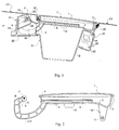
- FIG. 1 there is shown an embodiment of a system according to the invention, designated by the general reference S, in place in an opening in the outer face of a body of vehicle, consisting of a skin C 1 , C 2 and a lining (not shown).
- This system essentially consists of the combination of a hatch T, having the constitution illustrated in detail in Figures 2 and 3, and a main volume or bowl B, in the bottom of which is housed the mouth of the pipe fuel, with its cap, and which are joined by molding two auxiliary volumes V 1 and V 2 .
- volume V 1 and V 2 can take several variants, as illustrated in FIGS. 4 to 9 and 12.
- the arm 4 - 5 is made integral with the hatch proper 1 - 2, by jamming the knuckle 5 in a housing (9) formed in the lining 2 ( Figures 1 - 3) or between the skin 1 and the lining 2 (figure 12).
- the arm 4 - 5 can also come from molding in a single piece with the skin 1 or the lining 2.
- the branches 4, 4 ′ of the swan neck are molded in the form of boxes, which gives said swan neck a volume which ensures the rigidity of the arm and, consequently, of the entire arm and the hatch, during their repeated pivoting.
- a tab 10 perpendicular to the plane of the hatch has a slot 11 intended for locking the hatch as will be seen below.
- a hook 12 towards the bottom of the interior face of the hatch is intended for hooking the plug during filling.
- the bowl B is associated by molding a first auxiliary volume V1 consisting of two horizontal cheeks 30, 30 'and a vertical peripheral wall 13, comprising a front portion located directly behind the body C 1 and a lateral portion 31, this volume V 1 , constituting a housing for a part forming a cover and a spring, appearing in FIG. 1, and two embodiments of which are shown in detail in FIGS. 5 to 9.
- This part is composed in the two cases of a base 20 secured to two cheeks 21 and a back 22.
- this part is crossed by the pivot axis 29 of the arm 4 - 5, this axis being metallic and carried by bearings 32, 32 'provided in the cheeks 30, 30' of volume V 1 .
- said part or housing is fixed to the volume V1 by screwing or clipping.
- each cheek 21 has at its upper part a half-bearing 24, intended to receive the ends 7 of the pivot axis of the swan neck arm, these half bearings 24 cooperating with half-bearings 25 oriented in opposite directions, carried by the wall 13 (see FIG. 4).
- the pivot axis 7 constitutes an extension of the spacer 6 joining the arms 4, 4 'and is made of plastic.
- the housing is then fixed to the volume V 1 , by means of four screws passing through holes 23.
- the invention provides that the internal face of the wall 22 carries an elastic U-shaped blade 26, the free branch 27 of which exerts elastic pressure on one or the other of the flats 8, 8 ′, as a function of the position of the hatch, which stabilizes said hatch in said position.
- the housing instead of being introduced into the volume V 1 from the rear, as in the previous embodiments, is introduced laterally, at roughly parallel to bodywork C 1 .
- the volume V 1 comprises a rear vertical partition 33 on which the base 20 of the housing comes to lean. The attachment of the housing can then simply be carried out by two clips, although it is a plastic axis.
- a second auxiliary volume V 2 is also secured by molding with the main volume B and the first auxiliary volume V 1 .
- this second auxiliary volume V 2 is intended to receive a remote locking mechanism of the hatch P in the closed position.
- This mechanism symbolically designated by the reference 40, can be of any construction, consisting of a movable element, axially or in rotation, to be housed in the lumen 11 of the tab 10 carried by the hatch (see FIG. 2) .
- the control of this rod can be done automatically, for example simultaneously with the central locking of the doors and / or the trunk, or manually. It may include a pre-unlocking system, allowing the hatch to be ajar to facilitate its operation.
- Such a mechanism requiring only little energy, can be of smaller dimensions than those commonly used for doors, which allows it to be housed in a housing which can be introduced into a volume V 2 completely closed or partially open. on the outside, except on one end (figure 12). According to a variant, it is the volume V 2 itself which constitutes a housing comprising a cover 41 (FIG. 1).
- a seal 50 made of elastomeric material is provided between the assembly formed by the main volume and the two auxiliary volumes V 1 and V 2 on the one hand, and the bodywork C 1 C 2 on the other hand, and finally the inner edge of the hatch.
- This seal firstly ensures the self-centering of said assembly in the opening of the bodywork and secondly the seal between the interior of said assembly and the peripheral zone which surrounds it inside the bodywork, and for this purpose, it has on its inner periphery flexible stops such as 51 ( Figure 4) which allow self-centering of the hatch in the closed position.
- this seal 50 is deformed inwardly by the body C 1 , C 2 , when the assembly according to the invention is put in place.
- This seal can be made of elastomeric material molded simultaneously with the bowl and the auxiliary volumes, or simply be attached to the latter.
- the bowl B comprises, under its front periphery, at least two legs 60 (FIG. 4) which slide under corresponding elements (62) of the bodywork C 1 and under its rear periphery a clip 61 coming to lock in a corresponding element (63) of the bodywork C 2 (FIG. 10).
- the clipping system 61 can be oriented so as to allow an insertion substantially perpendicular.
- the installation of the system according to the invention is therefore done very simply and without any tools, by inserting the whole assembly (except possibly the hatch T), in the opening provided in the bodywork C 1 - C 2 , first by the legs 60, then after immobilization tilting by clipping of 61.
- the assembly can be put in place in the housing 20 - 21 - 22 already occupying its location in the first auxiliary volume V 1 , by simple sliding of the plastic pins 7 on appropriate ramps made on the cheeks 21, up to the bearings 24 - 25, and this even after assembly of the bowl assembly B and the volumes V 1 , V 2 on the vehicle .
Priority Applications (3)
| Application Number | Priority Date | Filing Date | Title |
|---|---|---|---|
| ES95440082T ES2100761T3 (es) | 1995-12-01 | 1995-12-01 | Sistema de tapa para deposito de carburante. |
| EP19950440082 EP0760306B1 (de) | 1995-12-01 | 1995-12-01 | Tankklappe |
| DE1995600202 DE69500202T2 (de) | 1995-12-01 | 1995-12-01 | Tankklappe |
Applications Claiming Priority (1)
| Application Number | Priority Date | Filing Date | Title |
|---|---|---|---|
| EP19950440082 EP0760306B1 (de) | 1995-12-01 | 1995-12-01 | Tankklappe |
Publications (2)
| Publication Number | Publication Date |
|---|---|
| EP0760306A1 true EP0760306A1 (de) | 1997-03-05 |
| EP0760306B1 EP0760306B1 (de) | 1997-03-26 |
Family
ID=8221597
Family Applications (1)
| Application Number | Title | Priority Date | Filing Date |
|---|---|---|---|
| EP19950440082 Expired - Lifetime EP0760306B1 (de) | 1995-12-01 | 1995-12-01 | Tankklappe |
Country Status (3)
| Country | Link |
|---|---|
| EP (1) | EP0760306B1 (de) |
| DE (1) | DE69500202T2 (de) |
| ES (1) | ES2100761T3 (de) |
Cited By (7)
| Publication number | Priority date | Publication date | Assignee | Title |
|---|---|---|---|---|
| EP0796754A1 (de) * | 1996-03-21 | 1997-09-24 | Mittelhäuser, Bernhard | Vorrichtung zum Abdecken des Tankstutzens an Kraftfahrzeugen mittels Tankklappe |
| DE19827194A1 (de) * | 1998-06-18 | 1999-12-23 | Volkswagen Ag | Verschlußklappe für eine Tankmulde eines Kraftfahrzeugs |
| EP1260400A3 (de) * | 2001-05-24 | 2004-12-15 | Maier, S. Coop. | Deckel |
| EP1508465A1 (de) * | 2003-08-21 | 2005-02-23 | Volkswagen Aktiengesellschaft | Tankklappenanordnung für ein Kraftfahrzeug sowie Verfahren zu ihrer Herstellung |
| EP1829727A2 (de) * | 2006-03-01 | 2007-09-05 | FIAT AUTO S.p.A. | Klappeneinheit für den Kraftstoffeinfüllstutzen eines Kraftfahrzeuges |
| WO2011026532A1 (de) * | 2009-09-02 | 2011-03-10 | Gm Global Technology Operations, Inc. | Tankklappenmodul |
| CN104512244A (zh) * | 2013-10-02 | 2015-04-15 | 通用汽车环球科技运作有限责任公司 | 油箱盖模块 |
Families Citing this family (3)
| Publication number | Priority date | Publication date | Assignee | Title |
|---|---|---|---|---|
| DE10160652B4 (de) * | 2001-12-11 | 2009-11-26 | GM Global Technology Operations, Inc., Detroit | Kraftfahrzeug mit einer Tankklappe und einer Rückleuchte |
| DE102012019796A1 (de) * | 2012-10-10 | 2013-09-26 | Audi Ag | Ladevorrichtung für ein Fahrzeug und Fahrzeug |
| CN108454386A (zh) * | 2018-04-11 | 2018-08-28 | 北京汽车研究总院有限公司 | 车辆加油口底座和具有其的车辆 |
Citations (8)
| Publication number | Priority date | Publication date | Assignee | Title |
|---|---|---|---|---|
| DE7328516U (de) * | 1973-11-15 | Bossert K Druckguss Metallwaren | Anordnung zur Abdeckung einer fur den Tankstutzen eines Kraftfahrzeugs vorgesehenen Karosseneoffnung | |
| DE3118267A1 (de) * | 1980-11-13 | 1982-06-09 | K.K.P. Konstruktive Kunststoff-Produkte Handelsgesellschaft Mbh, 8744 Mellrichstadt | Klappdeckel fuer oeffnungen in kraftfahrzeugkarosserien oder dgl. |
| DE3301072A1 (de) * | 1983-01-14 | 1984-07-19 | Itw-Ateco Gmbh, 2000 Norderstedt | Tankmulde fuer kraftfahrzeuge |
| EP0273525A2 (de) * | 1986-12-30 | 1988-07-06 | ALFA LANCIA S.p.A. | Haltevorrichtung für den Füllstutzen von Kraftfahrzeugen |
| US4782978A (en) * | 1987-09-03 | 1988-11-08 | General Motors Corporation | Remotely releasable fuel filler door with controlled opening |
| US5165749A (en) * | 1991-07-22 | 1992-11-24 | Molmec, Inc. | Gas cap cover adjustment device |
| DE4416992A1 (de) * | 1993-05-13 | 1994-11-24 | Yazaki Corp | Wasserdichte Verschlußanordnung für Ladeanschlußvorrichtungen |
| US5437491A (en) | 1994-04-07 | 1995-08-01 | Illinois Tool Works Inc. | Fuel door housing |
-
1995
- 1995-12-01 DE DE1995600202 patent/DE69500202T2/de not_active Expired - Fee Related
- 1995-12-01 ES ES95440082T patent/ES2100761T3/es not_active Expired - Lifetime
- 1995-12-01 EP EP19950440082 patent/EP0760306B1/de not_active Expired - Lifetime
Patent Citations (8)
| Publication number | Priority date | Publication date | Assignee | Title |
|---|---|---|---|---|
| DE7328516U (de) * | 1973-11-15 | Bossert K Druckguss Metallwaren | Anordnung zur Abdeckung einer fur den Tankstutzen eines Kraftfahrzeugs vorgesehenen Karosseneoffnung | |
| DE3118267A1 (de) * | 1980-11-13 | 1982-06-09 | K.K.P. Konstruktive Kunststoff-Produkte Handelsgesellschaft Mbh, 8744 Mellrichstadt | Klappdeckel fuer oeffnungen in kraftfahrzeugkarosserien oder dgl. |
| DE3301072A1 (de) * | 1983-01-14 | 1984-07-19 | Itw-Ateco Gmbh, 2000 Norderstedt | Tankmulde fuer kraftfahrzeuge |
| EP0273525A2 (de) * | 1986-12-30 | 1988-07-06 | ALFA LANCIA S.p.A. | Haltevorrichtung für den Füllstutzen von Kraftfahrzeugen |
| US4782978A (en) * | 1987-09-03 | 1988-11-08 | General Motors Corporation | Remotely releasable fuel filler door with controlled opening |
| US5165749A (en) * | 1991-07-22 | 1992-11-24 | Molmec, Inc. | Gas cap cover adjustment device |
| DE4416992A1 (de) * | 1993-05-13 | 1994-11-24 | Yazaki Corp | Wasserdichte Verschlußanordnung für Ladeanschlußvorrichtungen |
| US5437491A (en) | 1994-04-07 | 1995-08-01 | Illinois Tool Works Inc. | Fuel door housing |
Cited By (14)
| Publication number | Priority date | Publication date | Assignee | Title |
|---|---|---|---|---|
| EP0796754A1 (de) * | 1996-03-21 | 1997-09-24 | Mittelhäuser, Bernhard | Vorrichtung zum Abdecken des Tankstutzens an Kraftfahrzeugen mittels Tankklappe |
| DE19827194B4 (de) * | 1998-06-18 | 2012-06-06 | Volkswagen Ag | Verschlußklappe für eine Tankmulde eines Kraftfahrzeugs |
| DE19827194A1 (de) * | 1998-06-18 | 1999-12-23 | Volkswagen Ag | Verschlußklappe für eine Tankmulde eines Kraftfahrzeugs |
| EP1260400A3 (de) * | 2001-05-24 | 2004-12-15 | Maier, S. Coop. | Deckel |
| EP1508465A1 (de) * | 2003-08-21 | 2005-02-23 | Volkswagen Aktiengesellschaft | Tankklappenanordnung für ein Kraftfahrzeug sowie Verfahren zu ihrer Herstellung |
| EP1829727A3 (de) * | 2006-03-01 | 2009-08-05 | FIAT AUTO S.p.A. | Klappeneinheit für den Kraftstoffeinfüllstutzen eines Kraftfahrzeuges |
| EP1829727A2 (de) * | 2006-03-01 | 2007-09-05 | FIAT AUTO S.p.A. | Klappeneinheit für den Kraftstoffeinfüllstutzen eines Kraftfahrzeuges |
| WO2011026532A1 (de) * | 2009-09-02 | 2011-03-10 | Gm Global Technology Operations, Inc. | Tankklappenmodul |
| CN102395485A (zh) * | 2009-09-02 | 2012-03-28 | 通用汽车环球科技运作有限责任公司 | 油箱盖模块 |
| GB2485285A (en) * | 2009-09-02 | 2012-05-09 | Gm Global Tech Operations Inc | Fuel tank cover module |
| US8556326B2 (en) | 2009-09-02 | 2013-10-15 | GM Global Technology Operations LLC | Fuel tank cover module |
| CN102395485B (zh) * | 2009-09-02 | 2015-06-17 | 通用汽车环球科技运作有限责任公司 | 油箱盖模块 |
| GB2485285B (en) * | 2009-09-02 | 2016-02-24 | Gm Global Tech Operations Inc | Fuel tank cover module |
| CN104512244A (zh) * | 2013-10-02 | 2015-04-15 | 通用汽车环球科技运作有限责任公司 | 油箱盖模块 |
Also Published As
| Publication number | Publication date |
|---|---|
| DE69500202T2 (de) | 1997-10-30 |
| DE69500202D1 (de) | 1997-05-15 |
| EP0760306B1 (de) | 1997-03-26 |
| ES2100761T3 (es) | 1997-06-16 |
Similar Documents
| Publication | Publication Date | Title |
|---|---|---|
| CA1097385A (fr) | Plinthe automatique | |
| FR2759729A1 (fr) | Dispositif pour commander l'ouverture et la fermeture de la malle arriere et de la plage arriere d'un vehicule decouvrable | |
| EP0760306B1 (de) | Tankklappe | |
| EP0448452B1 (de) | Verbindungsglied, um einen Scheibenwischerarm mit einem Scheibenwischerblatt zu verbinden | |
| EP1227948A1 (de) | Tankverschlussdeckel für kraftfahrzeug | |
| FR2736025A1 (fr) | Essuie-glace pour vehicule automobile comportant un connecteur muni d'un capot articule | |
| FR2737192A1 (fr) | Boitier a couvercle pivotant pourvu d'une articulation a pattes souples | |
| FR2771972A1 (fr) | Dispositif de reserve pour un reservoir de carburant de vehicule automobile | |
| FR2519927A1 (fr) | Dispositif de coffre a bagages sur petits vehicules | |
| FR2590849A1 (fr) | Dispositif de couverture pour compartiment de rangement de capote pliable de vehicule | |
| FR2834487A1 (fr) | Dispositif d'ouverture et de fermeture du capot du coffre arriere d'un vehicule decouvrable a toit repliable | |
| EP0518760A1 (de) | Auf einem Scheibenwischerblatt montierte Vorrichtung für Waschflüssigkeitsejektion | |
| FR2658060A1 (fr) | Porte-filtre pour une cafetiere ou une theiere muni d'un dispositif de securite contre un ecoulement non desire du liquide. | |
| FR2739816A1 (fr) | Projecteur pour vehicules | |
| EP0742329B1 (de) | Verriegelungsvorrichtung für Kraftwagenflügel mit verbesserten Einbaumitteln für Verkleidungskappe | |
| FR2620090A3 (fr) | Systeme de fixation d'un dispositif lumineux plus particulierement d'un dispositif d'eclairage ou de signalisation, notamment de vehicule automobile | |
| EP0481863B1 (de) | Dichtung für Fahrzeugschiebefenster | |
| FR2889115A1 (fr) | Systeme d'obturation d'un reservoir a carburant | |
| FR2888274A1 (fr) | Mecanisme de support d'un ouvrant de vehicule automobile et vehicule automobile en comportant application | |
| FR2746750A1 (fr) | Essuie-glace de vehicule automobile comportant une canalisation d'alimentation dissimulee sous un capot d'habillage | |
| FR2513577A1 (fr) | Toit ouvrant pouvant recevoir un store pare-soleil pour vehicule automobile | |
| EP0047194B1 (de) | Türgriff mit Betätigungsklappe, insbesondere für Kraftfahrzeuge | |
| EP0555146B1 (de) | Scheibenwischer mit Abdeckkappe, insbesondere für Kraftfahrzeuge | |
| CH682040A5 (en) | Bracelet for watch including small medicament container - has container incorporated in bracelet with clasp having appearance similar to that of other bracelet links | |
| FR2491402A1 (fr) | Pare-soleil, notamment pour vehicule automobile |
Legal Events
| Date | Code | Title | Description |
|---|---|---|---|
| GRAG | Despatch of communication of intention to grant |
Free format text: ORIGINAL CODE: EPIDOS AGRA |
|
| GRAH | Despatch of communication of intention to grant a patent |
Free format text: ORIGINAL CODE: EPIDOS IGRA |
|
| GRAH | Despatch of communication of intention to grant a patent |
Free format text: ORIGINAL CODE: EPIDOS IGRA |
|
| PUAI | Public reference made under article 153(3) epc to a published international application that has entered the european phase |
Free format text: ORIGINAL CODE: 0009012 |
|
| GRAA | (expected) grant |
Free format text: ORIGINAL CODE: 0009210 |
|
| 17P | Request for examination filed |
Effective date: 19951221 |
|
| AK | Designated contracting states |
Kind code of ref document: A1 Designated state(s): DE ES FR GB IT |
|
| AK | Designated contracting states |
Kind code of ref document: B1 Designated state(s): DE ES FR GB IT |
|
| PG25 | Lapsed in a contracting state [announced via postgrant information from national office to epo] |
Ref country code: IT Free format text: LAPSE BECAUSE OF FAILURE TO SUBMIT A TRANSLATION OF THE DESCRIPTION OR TO PAY THE FEE WITHIN THE PRESCRIBED TIME-LIMIT;WARNING: LAPSES OF ITALIAN PATENTS WITH EFFECTIVE DATE BEFORE 2007 MAY HAVE OCCURRED AT ANY TIME BEFORE 2007. THE CORRECT EFFECTIVE DATE MAY BE DIFFERENT FROM THE ONE RECORDED. Effective date: 19970326 Ref country code: GB Effective date: 19970326 |
|
| REF | Corresponds to: |
Ref document number: 69500202 Country of ref document: DE Date of ref document: 19970515 |
|
| REG | Reference to a national code |
Ref country code: ES Ref legal event code: FG2A Ref document number: 2100761 Country of ref document: ES Kind code of ref document: T3 |
|
| GBV | Gb: ep patent (uk) treated as always having been void in accordance with gb section 77(7)/1977 [no translation filed] |
Effective date: 19970326 |
|
| PLBE | No opposition filed within time limit |
Free format text: ORIGINAL CODE: 0009261 |
|
| STAA | Information on the status of an ep patent application or granted ep patent |
Free format text: STATUS: NO OPPOSITION FILED WITHIN TIME LIMIT |
|
| 26N | No opposition filed | ||
| PGFP | Annual fee paid to national office [announced via postgrant information from national office to epo] |
Ref country code: DE Payment date: 19981216 Year of fee payment: 4 |
|
| PGFP | Annual fee paid to national office [announced via postgrant information from national office to epo] |
Ref country code: ES Payment date: 19981229 Year of fee payment: 4 |
|
| PG25 | Lapsed in a contracting state [announced via postgrant information from national office to epo] |
Ref country code: DE Free format text: LAPSE BECAUSE OF NON-PAYMENT OF DUE FEES Effective date: 20001003 |
|
| PG25 | Lapsed in a contracting state [announced via postgrant information from national office to epo] |
Ref country code: ES Free format text: LAPSE BECAUSE OF NON-PAYMENT OF DUE FEES Effective date: 20001202 |
|
| PGFP | Annual fee paid to national office [announced via postgrant information from national office to epo] |
Ref country code: FR Payment date: 20011227 Year of fee payment: 7 |
|
| PG25 | Lapsed in a contracting state [announced via postgrant information from national office to epo] |
Ref country code: FR Free format text: LAPSE BECAUSE OF NON-PAYMENT OF DUE FEES Effective date: 20030901 |
|
| REG | Reference to a national code |
Ref country code: FR Ref legal event code: ST |
|
| REG | Reference to a national code |
Ref country code: ES Ref legal event code: FD2A Effective date: 20010113 |