EP0760072B1 - Heating and ventilation system for a building - Google Patents
Heating and ventilation system for a building Download PDFInfo
- Publication number
- EP0760072B1 EP0760072B1 EP95920353A EP95920353A EP0760072B1 EP 0760072 B1 EP0760072 B1 EP 0760072B1 EP 95920353 A EP95920353 A EP 95920353A EP 95920353 A EP95920353 A EP 95920353A EP 0760072 B1 EP0760072 B1 EP 0760072B1
- Authority
- EP
- European Patent Office
- Prior art keywords
- air
- floor
- building
- barrier
- beneath
- Prior art date
- Legal status (The legal status is an assumption and is not a legal conclusion. Google has not performed a legal analysis and makes no representation as to the accuracy of the status listed.)
- Expired - Lifetime
Links
- 238000010438 heat treatment Methods 0.000 title claims abstract description 10
- 238000009423 ventilation Methods 0.000 title description 2
- 230000004888 barrier function Effects 0.000 claims abstract description 38
- 239000000463 material Substances 0.000 claims abstract description 15
- 230000002093 peripheral effect Effects 0.000 claims abstract description 3
- 238000010276 construction Methods 0.000 claims description 11
- XLYOFNOQVPJJNP-UHFFFAOYSA-N water Substances O XLYOFNOQVPJJNP-UHFFFAOYSA-N 0.000 claims description 6
- 238000009413 insulation Methods 0.000 claims description 5
- 230000003319 supportive effect Effects 0.000 claims description 3
- 239000010865 sewage Substances 0.000 claims description 2
- 239000003570 air Substances 0.000 description 94
- 239000010410 layer Substances 0.000 description 12
- 230000008901 benefit Effects 0.000 description 9
- 239000012528 membrane Substances 0.000 description 9
- 239000004033 plastic Substances 0.000 description 3
- 229920003023 plastic Polymers 0.000 description 3
- 239000002985 plastic film Substances 0.000 description 3
- 239000012080 ambient air Substances 0.000 description 2
- 238000001816 cooling Methods 0.000 description 2
- 230000004048 modification Effects 0.000 description 2
- 238000012986 modification Methods 0.000 description 2
- 239000011505 plaster Substances 0.000 description 2
- 239000011120 plywood Substances 0.000 description 2
- 230000015572 biosynthetic process Effects 0.000 description 1
- 230000001413 cellular effect Effects 0.000 description 1
- 238000004891 communication Methods 0.000 description 1
- 239000004020 conductor Substances 0.000 description 1
- 230000008878 coupling Effects 0.000 description 1
- 238000010168 coupling process Methods 0.000 description 1
- 238000005859 coupling reaction Methods 0.000 description 1
- 230000001419 dependent effect Effects 0.000 description 1
- 238000011161 development Methods 0.000 description 1
- 230000018109 developmental process Effects 0.000 description 1
- 238000007599 discharging Methods 0.000 description 1
- 230000000694 effects Effects 0.000 description 1
- 239000004744 fabric Substances 0.000 description 1
- 230000002349 favourable effect Effects 0.000 description 1
- 229920002457 flexible plastic Polymers 0.000 description 1
- 238000009434 installation Methods 0.000 description 1
- 239000007788 liquid Substances 0.000 description 1
- 239000011241 protective layer Substances 0.000 description 1
- 229910052704 radon Inorganic materials 0.000 description 1
- SYUHGPGVQRZVTB-UHFFFAOYSA-N radon atom Chemical compound [Rn] SYUHGPGVQRZVTB-UHFFFAOYSA-N 0.000 description 1
- 230000003134 recirculating effect Effects 0.000 description 1
- 230000009467 reduction Effects 0.000 description 1
- 239000011150 reinforced concrete Substances 0.000 description 1
- 238000005496 tempering Methods 0.000 description 1
- 238000011144 upstream manufacturing Methods 0.000 description 1
Images

Classifications
-
- F—MECHANICAL ENGINEERING; LIGHTING; HEATING; WEAPONS; BLASTING
- F24—HEATING; RANGES; VENTILATING
- F24F—AIR-CONDITIONING; AIR-HUMIDIFICATION; VENTILATION; USE OF AIR CURRENTS FOR SCREENING
- F24F12/00—Use of energy recovery systems in air conditioning, ventilation or screening
- F24F12/001—Use of energy recovery systems in air conditioning, ventilation or screening with heat-exchange between supplied and exhausted air
- F24F12/006—Use of energy recovery systems in air conditioning, ventilation or screening with heat-exchange between supplied and exhausted air using an air-to-air heat exchanger
-
- E—FIXED CONSTRUCTIONS
- E04—BUILDING
- E04B—GENERAL BUILDING CONSTRUCTIONS; WALLS, e.g. PARTITIONS; ROOFS; FLOORS; CEILINGS; INSULATION OR OTHER PROTECTION OF BUILDINGS
- E04B1/00—Constructions in general; Structures which are not restricted either to walls, e.g. partitions, or floors or ceilings or roofs
- E04B1/62—Insulation or other protection; Elements or use of specified material therefor
- E04B1/74—Heat, sound or noise insulation, absorption, or reflection; Other building methods affording favourable thermal or acoustical conditions, e.g. accumulating of heat within walls
- E04B1/76—Heat, sound or noise insulation, absorption, or reflection; Other building methods affording favourable thermal or acoustical conditions, e.g. accumulating of heat within walls specifically with respect to heat only
-
- F—MECHANICAL ENGINEERING; LIGHTING; HEATING; WEAPONS; BLASTING
- F24—HEATING; RANGES; VENTILATING
- F24D—DOMESTIC- OR SPACE-HEATING SYSTEMS, e.g. CENTRAL HEATING SYSTEMS; DOMESTIC HOT-WATER SUPPLY SYSTEMS; ELEMENTS OR COMPONENTS THEREFOR
- F24D5/00—Hot-air central heating systems; Exhaust gas central heating systems
-
- F—MECHANICAL ENGINEERING; LIGHTING; HEATING; WEAPONS; BLASTING
- F24—HEATING; RANGES; VENTILATING
- F24F—AIR-CONDITIONING; AIR-HUMIDIFICATION; VENTILATION; USE OF AIR CURRENTS FOR SCREENING
- F24F5/00—Air-conditioning systems or apparatus not covered by F24F1/00 or F24F3/00, e.g. using solar heat or combined with household units such as an oven or water heater
- F24F5/0046—Air-conditioning systems or apparatus not covered by F24F1/00 or F24F3/00, e.g. using solar heat or combined with household units such as an oven or water heater using natural energy, e.g. solar energy, energy from the ground
- F24F5/005—Air-conditioning systems or apparatus not covered by F24F1/00 or F24F3/00, e.g. using solar heat or combined with household units such as an oven or water heater using natural energy, e.g. solar energy, energy from the ground using energy from the ground by air circulation, e.g. "Canadian well"
-
- F—MECHANICAL ENGINEERING; LIGHTING; HEATING; WEAPONS; BLASTING
- F24—HEATING; RANGES; VENTILATING
- F24F—AIR-CONDITIONING; AIR-HUMIDIFICATION; VENTILATION; USE OF AIR CURRENTS FOR SCREENING
- F24F7/00—Ventilation
- F24F7/04—Ventilation with ducting systems, e.g. by double walls; with natural circulation
- F24F7/06—Ventilation with ducting systems, e.g. by double walls; with natural circulation with forced air circulation, e.g. by fan positioning of a ventilator in or against a conduit
-
- F—MECHANICAL ENGINEERING; LIGHTING; HEATING; WEAPONS; BLASTING
- F24—HEATING; RANGES; VENTILATING
- F24D—DOMESTIC- OR SPACE-HEATING SYSTEMS, e.g. CENTRAL HEATING SYSTEMS; DOMESTIC HOT-WATER SUPPLY SYSTEMS; ELEMENTS OR COMPONENTS THEREFOR
- F24D5/00—Hot-air central heating systems; Exhaust gas central heating systems
- F24D5/06—Hot-air central heating systems; Exhaust gas central heating systems operating without discharge of hot air into the space or area to be heated
- F24D5/10—Hot-air central heating systems; Exhaust gas central heating systems operating without discharge of hot air into the space or area to be heated with hot air led through heat-exchange ducts in the walls, floor or ceiling
-
- Y—GENERAL TAGGING OF NEW TECHNOLOGICAL DEVELOPMENTS; GENERAL TAGGING OF CROSS-SECTIONAL TECHNOLOGIES SPANNING OVER SEVERAL SECTIONS OF THE IPC; TECHNICAL SUBJECTS COVERED BY FORMER USPC CROSS-REFERENCE ART COLLECTIONS [XRACs] AND DIGESTS
- Y02—TECHNOLOGIES OR APPLICATIONS FOR MITIGATION OR ADAPTATION AGAINST CLIMATE CHANGE
- Y02B—CLIMATE CHANGE MITIGATION TECHNOLOGIES RELATED TO BUILDINGS, e.g. HOUSING, HOUSE APPLIANCES OR RELATED END-USER APPLICATIONS
- Y02B10/00—Integration of renewable energy sources in buildings
- Y02B10/40—Geothermal heat-pumps
-
- Y—GENERAL TAGGING OF NEW TECHNOLOGICAL DEVELOPMENTS; GENERAL TAGGING OF CROSS-SECTIONAL TECHNOLOGIES SPANNING OVER SEVERAL SECTIONS OF THE IPC; TECHNICAL SUBJECTS COVERED BY FORMER USPC CROSS-REFERENCE ART COLLECTIONS [XRACs] AND DIGESTS
- Y02—TECHNOLOGIES OR APPLICATIONS FOR MITIGATION OR ADAPTATION AGAINST CLIMATE CHANGE
- Y02B—CLIMATE CHANGE MITIGATION TECHNOLOGIES RELATED TO BUILDINGS, e.g. HOUSING, HOUSE APPLIANCES OR RELATED END-USER APPLICATIONS
- Y02B30/00—Energy efficient heating, ventilation or air conditioning [HVAC]
- Y02B30/54—Free-cooling systems
-
- Y—GENERAL TAGGING OF NEW TECHNOLOGICAL DEVELOPMENTS; GENERAL TAGGING OF CROSS-SECTIONAL TECHNOLOGIES SPANNING OVER SEVERAL SECTIONS OF THE IPC; TECHNICAL SUBJECTS COVERED BY FORMER USPC CROSS-REFERENCE ART COLLECTIONS [XRACs] AND DIGESTS
- Y02—TECHNOLOGIES OR APPLICATIONS FOR MITIGATION OR ADAPTATION AGAINST CLIMATE CHANGE
- Y02B—CLIMATE CHANGE MITIGATION TECHNOLOGIES RELATED TO BUILDINGS, e.g. HOUSING, HOUSE APPLIANCES OR RELATED END-USER APPLICATIONS
- Y02B30/00—Energy efficient heating, ventilation or air conditioning [HVAC]
- Y02B30/56—Heat recovery units
Definitions
- the present invention relates to a system for heating and ventilating a building which includes a generally peripheral foundation wall or edge beam which supports the external walls of the building, a floor construction which defines residential floor areas in the building, a space located beneath the floor construction and contained within the foundation wall, and openings which pass through the floor construction in the proximity of the external walls of the building to enable air to pass from said underlying space to the residential areas of the building.
- a system according to the preamble of claim 1 is known from SE-B-468 441, where the building foundations beneath the floor define a space which can be referred to generally as a miniature cellar or crawl in space.
- This space is thermally insulated and is sufficiently large to accommodate service equipment such as heat exchangers, water heaters, water and sewage connections, and the like.
- Exhaust air is ducted from the building interior to a heat exchanger in the service space and then discharged as extract air from the foundations/the building, to atmosphere through an outlet duct.
- Ambient or outdoor air is taken as supply air through an inlet duct and passed to a heat exchanger for heat exchange with the exhaust air, from where the supply air is passed to the service space.
- the supply air is then passed from the service space to the residential areas in the building, through a slot which extends around the perimeter of the external walls and the floor.
- An object of the invention is to provide a system which will enable the floor to be heated with the aid of relatively simple means and therewith at relatively low costs, by passing and at tempering air from the residential areas of the building through the space beneath the floor into surface enlarged contact with the underside of the floor.
- Another object of the invention is to provide a system which utilizes a substantial part of the energy contained by the building exhaust air without requiring the use of a true heat exchanger to this end.
- the exhaust air is then allowed to flow to the surrounding atmosphere.
- the air-permeable material may extend to the vicinity of the ground surface outside the edge beam/foundation wall.
- the air-permeable material may extend conveniently over the whole area of the foundations, or at least over the areas in which equipment is to stand.
- the exhaust air delivers its heat content to the ground underlying the foundations and also to the air-permeable material and/or to the edge beam/foundation wall, so that the heat carried by the exhaust air will have slowly been extracted therefrom before the exhaust air as extract air is conducted to the surrounding atmosphere, while at the same time the barrier has kept the exhaust air separate from the circulation air and possibly also from a service space beneath a self-supporting floor structure.
- the inventive system provides a number of advantages, as will be evident to the person skilled in this art.
- One advantage is that after being heated, the circulating indoor air will heat the floor structure; this enables the air circulating in the residential areas to have a lower temperature while maintaining a subjective comfort level.
- ventilation exhaust air delivers its heat content to the ground and to the foundation wall/edge beam, so as to reduce the heat that is lost from the circulation air to the foundation wall and to the ground beneath the building.
- the air in the residential areas can be circulated at a rate of flow which is generally independent of the flow rate of the supply/exhaust air.
- the supply air can be mixed with the circulation air without the use of a heat exchanger, wherein the supply air can be controlled in a known manner so that it is not released into the residential areas until the temperature of the supply air is generally the same as that of the circulating air.
- the supply air can be conducted along a circulation air duct that extends through a heat exchanger and thereafter down into the surface-enlarged space beneath the floor.
- the supply air can be introduced through a large number of perforations distributed in the roof insulation and/or wall insulation of the building, such that the supply air will enter the residential areas of the building relatively slowly and therewith have time to be heated to the average temperature of the circulation air before arriving at the central parts of the residential areas.
- the inventive system can use a floor which is constructed from a relatively bid distributing slab or plate which is carried by flexurally rigid lattice-work structures capable of receiving and supporting conduits, such as electric cable ducting, liquid carrying conduits, gas conduits and the like and therewith facilitate installation of such conduits or ducts in the building, wherein water heaters, fans, electric cable trunking etc. can be placed in a space beneath the floor.
- conduits such as electric cable ducting, liquid carrying conduits, gas conduits and the like
- the free-supporting floor may have some other conventional construction, for instance a reinforced concrete slab construction, in which case the conduits are attached to the underside of the floor with the aid of conventional fasteners.
- the barrier may be placed on the sub-surface in said space and may optionally be covered with a protective layer to prevent damage when walked on.
- the service equipment may therewith be placed on top of the membrane and the circulation air allowed to flow through the bottom space which is downwardly delimited by the membrane.
- the membrane may be mounted on the underside of the flexurally rigid structures after having installed the cables, ducts and conduits, wherewith the barrier may have the form of sheets of plaster board, plywood, air-impervious insulating board or like materials.
- the air-permeable material can then have the form of a gravel bed or a bed of like material beneath the foundation wall/the edge beam.
- the edge beam/foundation wall itself may be made air permeable in the sub-barrier region thereof.
- the sub-region of the edge beam/foundation wall may be provided with a plurality of perforations configured to effect the transfer of heat with the mass of the edge beam/foundation wall.
- a layer of air conducting material such as a gravel bed, in those parts of the foundations at which the barrier lies against its underlying supporting surface.
- the invention has been described with reference to winter conditions, in which heat is delivered to the building with the intention of lowering heating costs.
- the inventive system also has benefits in the summer season when wishing to keep the building cool, by enabling the circulating air to be cooled.
- the floor surface is cooled so as to give a subjective impression that the floor temperature is lower than the actual air temperature in the residential areas.
- FIG. 1 there is shown a building which has a generally closed ring-like foundation 1 that supports a structural 2 comprised of floor elements 21 (see Figure 4).
- Each of the floor elements 21 has a surface-enlarged top flange 22, a much narrower bottom beam element 23 and a flexurally rigid lattice work construction 24 which connects the top flange 22 with the bottom beam element 23.
- the flanges 22 define a sub-floor structure 25.
- An air gap 26 is provided between the sub-floor 25 and the foundation wall 1 or the external walls 11 of the building, said gap extending essentially along the full length of said walls.
- the roof insulation 30 is of a known porous kind and ambient air is able to seep relatively slowly into the building interior and into the residential or living areas 32 of the building as supply air, due to sub-pressure conditions prevailing in the building.
- the insulation 30 may be provided with an air-permeable pressure equalizing layer, for instance a layer of fabric, which offers a resistance such as to cause the air to be distributed generally uniformly across the insulated area.
- Located beneath the sub-floor 25 is a service space or utilities space 3 whose bottom defining surface is delimited by an impervious barrier 15, in the illustrated case a membrane, eg made of flexible plastic sheet, wherein the edges of the barrier are sealingly connected to the foundation wall 1 around the perimeter thereof and beneath the base floor structure 2.
- the barrier may have a heat-insulating character and may, for instance, be comprised of a sheet of impervious flexible expanded plastic or cellular plastic.
- the space 3 accommodates a water heater 41, a fan unit 42 and a fan unit 44.
- a circulation air duct 50 draws in air from the residential areas 32 and conducts the air to the fan unit 42 installed in the utilities space 3, wherein the circulation air may optionally be heated in heating unit 43 prior to be brought into contact with the underside of the floor structure 25, where the air can disperse in surface-enlarged contact with the sub-floor 25 to the gap 26 while heating the surface of the floor 25 (floor heating).
- the air exiting from the gap 26 rises in the residential areas 32 and is recirculated through the openings 51 in the duct 50.
- Exhaust air is evacuated from toilet, bathroom and kitchen facilities through an exhaust air duct 60, which conducts the air to a fan unit 44.
- the fan unit 44 may optionally be fitted with a typical filter unit and functions to lead the exhaust air through the impervious barrier 15 and to the central space 7 between the membrane 15 and the ground.
- the space floor may be comprised of a layer of air-permeable material, such as a layer of gravel or like material. Similar gravel beds may be placed beneath the foundation walls 11 to establish a means of communication of the exhaust air with the outdoor surroundings, in a direction out from the intermediate space 7 and beneath the walls 1.
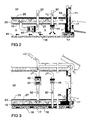
- Figure 2 shows a variant of the inventive system in which the barrier is mounted on the underside of the structural floor 2, to form a floor space 27 whose vertical extension or depth corresponds essentially to the vertical extension of the floor elements 21 minus the thickness of the upper flange, therewith to disperse the recirculating air through the floor structure.
- the barrier 15 may conveniently comprise panel elements, such as sheets of plaster board, plywood, or thermally insulating and air-impervious material, attached to the beam elements 23. Exhaust air can now be dispersed freely across the cross-sectional area of the foundations, wherein exhaust air/supply air can be led out through an air-conducting porous layer/bed 17 which holds the foundation wall spaced from the ground surface 18. Those parts of the foundation wall 1 that are located actually beneath the barrier 15 may also in this case be permeable to air.
- the sub-floor 25 is placed directly on the ground 18, via the preferably thermally insulating barrier 15 and a layer of bed of air-permeable material 17 (a gravel bed or like bed), therewith establishing a circulation-air distributing channel way 27 in the structural floor 2, the fan unit 42 for recirculated air also being placed in the residential area 32 of the building.
- the exhaust air fan unit 44 is also placed in the residential area 32.
- the barrier 15 may, eg, be formed by the bottom plate, the insulating layer and/or an impervious plastic sheet.
- supply air can be taken into the building in a conventional manner through a duct system which communicates with the surroundings, said supply air primarily being conducted into the circulation-air system and to the fan unit, from where the air is passed through the air heater and then through the floor structure prior to being dispersed in the residential areas 32.
- All of the embodiments shown in respective Figures 1, 2 and 3 includes an impervious barrier 15 which functions to screen the full area of the foundations beneath the base floor structure, such that the barrier 15 delimits downwardly a circulation space for the air mass in the residential areas of the building, wherein the circulation air can be caused to heat or warm a floor.
- the barrier 15 defines upwardly a space which receives exhaust air from the building, said exhaust air being intended to disperse or spread in the pressurized space defined between the barrier 15 and the foundation wall supportive layer and to pass therefrom through an air-permeable supportive layer beneath the foundation walls (or through perforations in the foundation walls beneath the barrier) to the building surroundings.
- an impervious plastic sheet may be placed on the ground 18 as protection against the ingress of moisture and radon gas, particularly when the floor structure is i self-supporting structure.
- One advantage afforded by the present invention is that in hot weather the building can be cooled by coupling a cooling source to the circulation-air duct 50, for instance the evaporator of a heat pump.
- a cooling source for instance the evaporator of a heat pump.
- Another advantage afforded by the inventive system is that with the aid of relatively simple means the residential or living areas of the building can be cooled in summer months by discharging exhaust air 60 directly to the outdoor surroundings (instead of passing the air down beneath the barrier 15) and by passing outside ambient air through the layer 17, the perforated foundation walls 1 and optionally also the layer 16 so as to cool the air, and thereafter to the residential areas of the building, with the aid of suitable fans, blowers and air ducts.
- this modification may include the provision of a branch connecting pipe in the duct 50 immediately upstream of the fan unit 42, and the provision of a switching valve downstream of the outlet of the air duct 60 to the fan unit 44, and the provision of a duct from the valve directly to the surrounding outdoor atmosphere.
Landscapes
- Engineering & Computer Science (AREA)
- Combustion & Propulsion (AREA)
- General Engineering & Computer Science (AREA)
- Mechanical Engineering (AREA)
- Chemical & Material Sciences (AREA)
- Physics & Mathematics (AREA)
- Life Sciences & Earth Sciences (AREA)
- Architecture (AREA)
- Sustainable Development (AREA)
- Sustainable Energy (AREA)
- Acoustics & Sound (AREA)
- Electromagnetism (AREA)
- Civil Engineering (AREA)
- Structural Engineering (AREA)
- Thermal Sciences (AREA)
- Building Environments (AREA)
Applications Claiming Priority (5)
| Application Number | Priority Date | Filing Date | Title |
|---|---|---|---|
| SE9401730 | 1994-05-19 | ||
| SE9401730A SE9401730L (sv) | 1993-07-19 | 1994-05-19 | Anordning för husuppvärmning och ventilation |
| SE9500123 | 1995-01-16 | ||
| SE9500123A SE9500123D0 (sv) | 1994-05-19 | 1995-01-16 | Systemlösning |
| PCT/SE1995/000569 WO1995032397A1 (en) | 1994-05-19 | 1995-05-19 | Heating and ventilation system for a building |
Publications (2)
| Publication Number | Publication Date |
|---|---|
| EP0760072A1 EP0760072A1 (en) | 1997-03-05 |
| EP0760072B1 true EP0760072B1 (en) | 2000-04-12 |
Family
ID=26662057
Family Applications (1)
| Application Number | Title | Priority Date | Filing Date |
|---|---|---|---|
| EP95920353A Expired - Lifetime EP0760072B1 (en) | 1994-05-19 | 1995-05-19 | Heating and ventilation system for a building |
Country Status (10)
| Country | Link |
|---|---|
| US (1) | US5954046A (pl) |
| EP (1) | EP0760072B1 (pl) |
| AU (1) | AU2582995A (pl) |
| CA (1) | CA2190639C (pl) |
| DK (1) | DK0760072T3 (pl) |
| FI (1) | FI107078B (pl) |
| NO (1) | NO308713B1 (pl) |
| PL (1) | PL178755B1 (pl) |
| SE (1) | SE9500123D0 (pl) |
| WO (1) | WO1995032397A1 (pl) |
Cited By (1)
| Publication number | Priority date | Publication date | Assignee | Title |
|---|---|---|---|---|
| CN106016436A (zh) * | 2016-06-03 | 2016-10-12 | 华北电力大学(保定) | 一种太阳能与地热能互补的建筑能源系统 |
Families Citing this family (34)
| Publication number | Priority date | Publication date | Assignee | Title |
|---|---|---|---|---|
| DE19533475B4 (de) * | 1995-09-12 | 2006-04-13 | Krecké, Edmond Dominique | Energieanlage für Gebäude |
| US6843718B2 (en) * | 2001-03-26 | 2005-01-18 | Johannes Schmitz | Method of guiding external air in a building shell and a building; and a method of temperature control of a building |
| US6679247B1 (en) * | 2001-05-16 | 2004-01-20 | David T. Gozikowski | Solar water heating |
| SE531216C2 (sv) * | 2005-03-16 | 2009-01-20 | Sten Engwall | Uppvärmningssystem, värmepump och uppvärmningsaggregat |
| FR2904007B1 (fr) * | 2006-07-21 | 2008-11-21 | Toulouse Inst Nat Polytech | Procede de depot de revetements ceramiques non oxydes. |
| US20080034681A1 (en) * | 2006-08-14 | 2008-02-14 | Paul Francis McDonald | First House II |
| US7789740B2 (en) * | 2006-11-10 | 2010-09-07 | Janesky Lawrence M | Crawlspace air apparatus |
| US20090229199A1 (en) * | 2008-03-10 | 2009-09-17 | Peapod Homes, Llc | Building structure with having spaces having improved temperature stability |
| ES2308942B1 (es) * | 2008-04-04 | 2009-09-22 | Edificios Sostenibles Getech,S.L | Nuevo modelo de edificio sostenible. |
| CN104864609A (zh) | 2009-02-02 | 2015-08-26 | 玻点太阳能有限公司 | 用温室聚集太阳能 |
| DE202009007559U1 (de) * | 2009-05-27 | 2009-08-27 | Voltwerk Electronics Gmbh | Wechselrichtergebäude |
| US8701773B2 (en) | 2010-07-05 | 2014-04-22 | Glasspoint Solar, Inc. | Oilfield application of solar energy collection |
| WO2012006288A2 (en) * | 2010-07-05 | 2012-01-12 | Glasspoint Solar, Inc. | Subsurface thermal energy storage of heat generated by concentrating solar power |
| US8752542B2 (en) | 2010-07-05 | 2014-06-17 | Glasspoint Solar, Inc. | Direct solar steam generation |
| WO2012128877A2 (en) | 2011-02-22 | 2012-09-27 | Glasspoint Solar, Inc. | Concentrating solar power with glasshouses |
| CN106052145B (zh) | 2010-07-05 | 2019-11-05 | 玻点太阳能有限公司 | 温室的聚光太阳能发电 |
| FR2962793A1 (fr) * | 2010-07-19 | 2012-01-20 | Philippe Malapert | Procede de regulation thermique par ventilation forcee d'un batiment incorporant un vide sanitaire et batiment pour la realisation de ce procede |
| CN103510546A (zh) * | 2012-06-30 | 2014-01-15 | 中国有色金属工业第六冶金建设有限公司 | 一种严冬下设备基础暖棚法防护施工方法 |
| US9200799B2 (en) | 2013-01-07 | 2015-12-01 | Glasspoint Solar, Inc. | Systems and methods for selectively producing steam from solar collectors and heaters for processes including enhanced oil recovery |
| US9874359B2 (en) | 2013-01-07 | 2018-01-23 | Glasspoint Solar, Inc. | Systems and methods for selectively producing steam from solar collectors and heaters |
| US9719268B2 (en) * | 2013-03-15 | 2017-08-01 | Aacer Acquisition, Llc | Ventilated athletic flooring systems and methods of assembling the same |
| JP6170375B2 (ja) * | 2013-08-26 | 2017-07-26 | 積水化学工業株式会社 | 空調システム及び建物 |
| JP2015045489A (ja) * | 2013-08-29 | 2015-03-12 | パナホーム株式会社 | 建物の空調システム |
| JP6235848B2 (ja) * | 2013-09-27 | 2017-11-22 | パナホーム株式会社 | 建物の空調システム |
| JP6219215B2 (ja) * | 2014-03-31 | 2017-10-25 | パナホーム株式会社 | 住宅の構造 |
| US9828740B1 (en) * | 2014-04-29 | 2017-11-28 | Arizona Foundation Solutions, LLC | System and method for stabilization of structures by control of soil moisture content |
| CN106999838A (zh) | 2014-10-23 | 2017-08-01 | 玻点太阳能有限公司 | 使用太阳能的气体净化和相关系统及方法 |
| AU2015335752A1 (en) | 2014-10-23 | 2017-05-04 | Glasspoint Solar, Inc. | Heat storage devices for solar steam generation, and associated systems and methods |
| JP6381449B2 (ja) * | 2015-01-08 | 2018-08-29 | 次彦 玉井 | 床暖房システム及び床暖房方法 |
| JP6625358B2 (ja) * | 2015-07-17 | 2019-12-25 | 旭化成ホームズ株式会社 | 空調システム |
| CN108603656A (zh) | 2016-02-01 | 2018-09-28 | 玻点太阳能有限公司 | 针对提高石油采收率的用于长距离输送质量受控的太阳能生成的蒸汽的分离器和混合器,以及相关的系统及方法 |
| FR3059086B1 (fr) * | 2016-11-23 | 2020-10-23 | Commissariat Energie Atomique | Systeme de production de chauffage et/ou d'eau chaude sanitaire, couplant une pompe a chaleur avec un puits enthalpique |
| JP6611266B2 (ja) * | 2017-03-31 | 2019-11-27 | パナソニックホームズ株式会社 | 住宅 |
| HU231047B1 (en) * | 2017-06-12 | 2020-01-28 | Civis Therm Kft | Geothermal insulating system and method |
Family Cites Families (9)
| Publication number | Priority date | Publication date | Assignee | Title |
|---|---|---|---|---|
| US2206119A (en) * | 1937-02-03 | 1940-07-02 | Automatic Control Corp | Building heating and cooling system |
| US2559871A (en) * | 1949-08-24 | 1951-07-10 | Frazer W Gay | House structure and heating system therefor |
| US4195441A (en) * | 1977-05-23 | 1980-04-01 | Baldwin Richard E | Solar greenhouse |
| US4602676A (en) * | 1979-07-03 | 1986-07-29 | Stephen J. Ledet, Jr. | Heat transfer and building support system |
| SE8301130D0 (sv) * | 1983-03-01 | 1983-03-01 | George Wegler | Betongelement med forstyvningar |
| US4578912A (en) * | 1983-06-30 | 1986-04-01 | Profoment Utvecklings Ab | Foundation for cellarless houses |
| SE454280B (sv) * | 1983-12-15 | 1988-04-18 | Tyrens Foeretagsgrupp Ab | Anordning for att vid en byggnad med en bottenplatta infora en luftvolym under bottenplattan |
| DE3801199A1 (de) * | 1988-01-18 | 1989-07-27 | Erhard Wolke | Verfahren zum energiesparenden beheizen von gebaeuden sowie einrichtung zur durchfuehrung des verfahrens |
| SE468441B (sv) * | 1991-05-10 | 1993-01-18 | Sten Engwall | Husgrund med serviceutrymme |
-
1995
- 1995-01-16 SE SE9500123A patent/SE9500123D0/xx unknown
- 1995-05-19 US US08/737,734 patent/US5954046A/en not_active Expired - Fee Related
- 1995-05-19 PL PL95317260A patent/PL178755B1/pl unknown
- 1995-05-19 AU AU25829/95A patent/AU2582995A/en not_active Abandoned
- 1995-05-19 DK DK95920353T patent/DK0760072T3/da active
- 1995-05-19 EP EP95920353A patent/EP0760072B1/en not_active Expired - Lifetime
- 1995-05-19 WO PCT/SE1995/000569 patent/WO1995032397A1/en not_active Ceased
- 1995-05-19 CA CA002190639A patent/CA2190639C/en not_active Expired - Fee Related
-
1996
- 1996-11-11 FI FI964513A patent/FI107078B/fi not_active IP Right Cessation
- 1996-11-15 NO NO964877A patent/NO308713B1/no not_active IP Right Cessation
Cited By (1)
| Publication number | Priority date | Publication date | Assignee | Title |
|---|---|---|---|---|
| CN106016436A (zh) * | 2016-06-03 | 2016-10-12 | 华北电力大学(保定) | 一种太阳能与地热能互补的建筑能源系统 |
Also Published As
| Publication number | Publication date |
|---|---|
| DK0760072T3 (da) | 2002-12-23 |
| SE9500123D0 (sv) | 1995-01-16 |
| EP0760072A1 (en) | 1997-03-05 |
| NO964877D0 (no) | 1996-11-15 |
| PL317260A1 (en) | 1997-04-01 |
| FI964513A7 (fi) | 1996-11-11 |
| US5954046A (en) | 1999-09-21 |
| NO308713B1 (no) | 2000-10-16 |
| CA2190639A1 (en) | 1995-11-30 |
| CA2190639C (en) | 2004-03-30 |
| WO1995032397A1 (en) | 1995-11-30 |
| AU2582995A (en) | 1995-12-18 |
| NO964877L (no) | 1996-11-15 |
| PL178755B1 (pl) | 2000-06-30 |
| FI107078B (fi) | 2001-05-31 |
| FI964513A0 (fi) | 1996-11-11 |
Similar Documents
| Publication | Publication Date | Title |
|---|---|---|
| US5954046A (en) | Heating and ventilation system for a building | |
| US4651805A (en) | Heat transfer and building support system | |
| US4602676A (en) | Heat transfer and building support system | |
| US5158501A (en) | Below grade heat recovery ventilator | |
| US4672887A (en) | Combination valance and conditioned air admission and return ducts | |
| RU2159899C2 (ru) | Система отопления и вентиляции зданий | |
| JP2954872B2 (ja) | 家 屋 | |
| JP2005201601A (ja) | 建物の暖房システム。 | |
| JP2002194827A (ja) | 建物の換気構造 | |
| JPH1144435A (ja) | 空気循環式空調型床暖房システムハウス | |
| US4538507A (en) | Air circulation system and air flow elements therefor | |
| JPH04244538A (ja) | 熱交換型強制換気式家屋 | |
| JP3895698B2 (ja) | 換気装置および床暖房装置を備えた建物 | |
| JP3029335U (ja) | 床下空間を活用した集中暖房換気方式を採用した木造住宅 | |
| RU96123901A (ru) | Система отопления и вентиляции здания | |
| SK42799A3 (en) | Building with a heating and a cooling system which includes a floor heating system and a fresh-air heating system | |
| JP2000240957A (ja) | フリーアクセスフロア用床暖房装置 | |
| JP3082112B2 (ja) | 逆梁床構造の住宅 | |
| JP3909405B2 (ja) | 暖房システム | |
| JP3558241B2 (ja) | 高気密高断熱住宅の換気暖房システム | |
| JP2564363B2 (ja) | 家 屋 | |
| JP3729361B2 (ja) | 家屋 | |
| JPH01179832A (ja) | 家屋 | |
| JP3097667U (ja) | 外断熱建物 | |
| JP2004162932A (ja) | 木造住宅に於ける床下調湿を利用した空調システム |
Legal Events
| Date | Code | Title | Description |
|---|---|---|---|
| PUAI | Public reference made under article 153(3) epc to a published international application that has entered the european phase |
Free format text: ORIGINAL CODE: 0009012 |
|
| 17P | Request for examination filed |
Effective date: 19961211 |
|
| AK | Designated contracting states |
Kind code of ref document: A1 Designated state(s): DE DK FR GB SE |
|
| 17Q | First examination report despatched |
Effective date: 19980904 |
|
| GRAG | Despatch of communication of intention to grant |
Free format text: ORIGINAL CODE: EPIDOS AGRA |
|
| GRAG | Despatch of communication of intention to grant |
Free format text: ORIGINAL CODE: EPIDOS AGRA |
|
| GRAG | Despatch of communication of intention to grant |
Free format text: ORIGINAL CODE: EPIDOS AGRA |
|
| GRAH | Despatch of communication of intention to grant a patent |
Free format text: ORIGINAL CODE: EPIDOS IGRA |
|
| GRAH | Despatch of communication of intention to grant a patent |
Free format text: ORIGINAL CODE: EPIDOS IGRA |
|
| GRAA | (expected) grant |
Free format text: ORIGINAL CODE: 0009210 |
|
| AK | Designated contracting states |
Kind code of ref document: B1 Designated state(s): DE DK FR GB SE |
|
| PG25 | Lapsed in a contracting state [announced via postgrant information from national office to epo] |
Ref country code: FR Free format text: LAPSE BECAUSE OF FAILURE TO SUBMIT A TRANSLATION OF THE DESCRIPTION OR TO PAY THE FEE WITHIN THE PRESCRIBED TIME-LIMIT Effective date: 20000412 |
|
| REF | Corresponds to: |
Ref document number: 69516278 Country of ref document: DE Date of ref document: 20000518 |
|
| PG25 | Lapsed in a contracting state [announced via postgrant information from national office to epo] |
Ref country code: DE Free format text: LAPSE BECAUSE OF FAILURE TO SUBMIT A TRANSLATION OF THE DESCRIPTION OR TO PAY THE FEE WITHIN THE PRESCRIBED TIME-LIMIT Effective date: 20000713 |
|
| EN | Fr: translation not filed | ||
| PLBE | No opposition filed within time limit |
Free format text: ORIGINAL CODE: 0009261 |
|
| STAA | Information on the status of an ep patent application or granted ep patent |
Free format text: STATUS: NO OPPOSITION FILED WITHIN TIME LIMIT |
|
| 26N | No opposition filed | ||
| REG | Reference to a national code |
Ref country code: GB Ref legal event code: IF02 |
|
| REG | Reference to a national code |
Ref country code: DK Ref legal event code: EGE |
|
| REG | Reference to a national code |
Ref country code: DK Ref legal event code: T3 |
|
| PGFP | Annual fee paid to national office [announced via postgrant information from national office to epo] |
Ref country code: DK Payment date: 20050526 Year of fee payment: 11 |
|
| PG25 | Lapsed in a contracting state [announced via postgrant information from national office to epo] |
Ref country code: DK Free format text: LAPSE BECAUSE OF NON-PAYMENT OF DUE FEES Effective date: 20060531 |
|
| REG | Reference to a national code |
Ref country code: DK Ref legal event code: EBP |
|
| PGFP | Annual fee paid to national office [announced via postgrant information from national office to epo] |
Ref country code: GB Payment date: 20090506 Year of fee payment: 15 |
|
| GBPC | Gb: european patent ceased through non-payment of renewal fee |
Effective date: 20100519 |
|
| PG25 | Lapsed in a contracting state [announced via postgrant information from national office to epo] |
Ref country code: GB Free format text: LAPSE BECAUSE OF NON-PAYMENT OF DUE FEES Effective date: 20100519 |
|
| PGFP | Annual fee paid to national office [announced via postgrant information from national office to epo] |
Ref country code: SE Payment date: 20121130 Year of fee payment: 19 |
|
| PG25 | Lapsed in a contracting state [announced via postgrant information from national office to epo] |
Ref country code: SE Free format text: LAPSE BECAUSE OF NON-PAYMENT OF DUE FEES Effective date: 20140520 |
|
| REG | Reference to a national code |
Ref country code: SE Ref legal event code: EUG |