EP0759532B1 - Einrichtung zur Aufnahme und Halterung von Flugkörpern in einem Startgerät - Google Patents
Einrichtung zur Aufnahme und Halterung von Flugkörpern in einem Startgerät Download PDFInfo
- Publication number
- EP0759532B1 EP0759532B1 EP96112503A EP96112503A EP0759532B1 EP 0759532 B1 EP0759532 B1 EP 0759532B1 EP 96112503 A EP96112503 A EP 96112503A EP 96112503 A EP96112503 A EP 96112503A EP 0759532 B1 EP0759532 B1 EP 0759532B1
- Authority
- EP
- European Patent Office
- Prior art keywords
- cam
- missile
- launcher
- spiral
- wedging
- Prior art date
- Legal status (The legal status is an assumption and is not a legal conclusion. Google has not performed a legal analysis and makes no representation as to the accuracy of the status listed.)
- Expired - Lifetime
Links
Images




Classifications
-
- B—PERFORMING OPERATIONS; TRANSPORTING
- B64—AIRCRAFT; AVIATION; COSMONAUTICS
- B64D—EQUIPMENT FOR FITTING IN OR TO AIRCRAFT; FLIGHT SUITS; PARACHUTES; ARRANGEMENT OR MOUNTING OF POWER PLANTS OR PROPULSION TRANSMISSIONS IN AIRCRAFT
- B64D7/00—Arrangement of military equipment, e.g. armaments, armament accessories or military shielding, in aircraft; Adaptations of armament mountings for aircraft
- B64D7/08—Arrangement of rocket launchers
-
- F—MECHANICAL ENGINEERING; LIGHTING; HEATING; WEAPONS; BLASTING
- F41—WEAPONS
- F41F—APPARATUS FOR LAUNCHING PROJECTILES OR MISSILES FROM BARRELS, e.g. CANNONS; LAUNCHERS FOR ROCKETS OR TORPEDOES; HARPOON GUNS
- F41F3/00—Rocket or torpedo launchers
- F41F3/04—Rocket or torpedo launchers for rockets
- F41F3/0406—Rail launchers
Definitions
- the invention relates to a device for receiving and holding missiles in a starting device according to the preamble of protection claim 1.
- Missiles or guided missiles have two or three T-shaped sliding shoes with which they are guided in the guide rail of the starter.
- the missile When loading, the missile is inserted into the guide rail and so far pushed in the direction of flight until a locking mechanism front slide shoe includes form-fitting.
- a play of several millimeters Between the guide rail of the Starting device and the missile there is a play of several millimeters, to enable easy loading.
- the missile In the loading position described above, the missile is inserted into the guide rails without play pressed, what by two scissors-like, wedge-shaped sheets done under spring force. Due to the point contact between the sheets and the glide shoe comes with the inevitable plane vibrations to pressure points and considerable abrasion on the shoes, so that the functional reliability the mechanical bracket after just a few hours of flight is no longer given. Since there are so-called double loading stations on some carrier aircraft where the starters are down by about 30 ° Verticals arranged diagonally to the left and to the right are scissors-like stored sheets loaded unevenly, thereby increasing the functional reliability is further reduced.
- the secure mounting of the missile is on or in the starter ensures that a Reibrichtgehemme special Design a relatively large area between the missile and the launcher in the form of a force pairing.
- This pair of forces in which an eccentric with a logarithmic spiral active surface against a missile surface acts and is supported on a surface of the starter, the remains recorded missiles also in the case of aircraft vibrations in the Stop position and prevents unintentional by the relatively large surface pressure
- the friction straightening bracket used is made robust, so that damage that could impair the functional safety, are largely excluded.
- the launcher 1 for a missile 2 has two opposite one another Guide rails 3 into which the missile 2 slides by means of a hanger 4 is inserted.
- This facility points to the beginning described prior art two scissors-like mounted on bolts 8, wedge-shaped sheets 7. Through these sheets only one is on the trailer 4 punctiform escapement, which leads to pressure points and aircraft vibrations considerable abrasion and finally to the unwanted release of the missile 2 the starting device 1 leads.
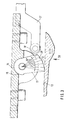
- a specially designed Reibrichtgehemme 9 for receiving and mounting of missiles 2 shown.
- the missile 2 is by means of Trailer 4 again in the guide rails 3 of the starter device 1 on both sides inserted.
- the Reibrichtgehemme 9 holds the missile 2 in one predetermined position on the starter 1 securely.
- One around a bolt 10 rotatably mounted eccentric 11 with its effective surface 12 inhibits one assigned surface 13 of the hanger 4.
- the effective surface 12 of the eccentric 11 is designed in the form of a logarithmic spiral, as shown in FIG. 3 is made clear. With the spherical surface facing away from this active surface 12 14 the eccentric is supported on the correspondingly shaped surface 15 of the Starting device 1 from.
- This supporting construction causes the pin 10th do not act the inhibiting forces, so that this bolt 10 in the Bore 16 can have a relatively small cross section.
- the spherical trained surface 14 of the eccentric 11 leads to the advantageous Line contact between the active surface 12 of the friction thumb 20 and the facing surface 13 of the hanger 4.
- the Bearing pin 10 has a relatively small diameter because it has no forces and Has to record moments, but only serves for positioning. The forces are basically about the eccentric 11 in its support or Transfer creation positions. There is also a fit between the bearing pin 10 and the corresponding mounting hole in the eccentric 11 is not required.
- the active surface 12 of the friction thumb 20 is in a logarithmic spiral in their inhibitory system on the counter surface 13 of the hanger 4 clearly recognizable.
- the eccentric 11 is in this inhibiting position by a Push rod 17 brought, which is in principle tangential to its front rounded end face presses on the eccentric 11.
- the front end face of the push rod 17 can also be rounded off with a roller or a roller wheel 18.
- the push rod 17 is in the front Position can be determined when inhibition occurs.
- the eccentric 11 is contrary to caused by the push rod 17 direction of movement by coil springs 19 automatically resettable, one end of each in a side recess 21st engages in the eccentric 11, while the other end of the screw around the ends of the bearing bolt 10 coiled coil spring 19 with the fixed Starter 1 is connected.
- a preferred embodiment of the spiral active surface 12 provides that in Angular steps of 10 ° each increase the radius uniformly is made.
- the support surface 14 facing away from the active surface 12 Eccentric 11 is spherical and lies on the corresponding trained area on the starting device 1.
- the circular in itself possible Design of the support surface 14 only causes a deterioration in execution random line-shaped contact between the active surface 12 of the Frictional thumb 20 and the surface 13 of the hanger 4.
- the spiral-shaped active surface 12 is finely machined. You can go to Increasing the frictional torque can also be roughened or a special one Obtained coating to control the frictional forces. Alternatively, you can special materials can be selected that optimal inhibition between the effective surface 12 of the eccentric 11 and the surface 13 of the hanger 4 and the Ensure missile 2.
- FIG. 5 shows the eccentric 11 with one of one Set screw 22 acted upon tension spring 21 shown. This arrangement does an automatic resetting of the eccentric 11.
Landscapes
- Engineering & Computer Science (AREA)
- Aviation & Aerospace Engineering (AREA)
- General Engineering & Computer Science (AREA)
- Aiming, Guidance, Guns With A Light Source, Armor, Camouflage, And Targets (AREA)
- Clamps And Clips (AREA)
- Pinball Game Machines (AREA)
Description
- Figur 1
- ein Startgerät mit einer Halteeinrichtung nach dem geschilderten Stand der Technik im Schnitt;
- Figur 2
- die Einrichtung zur Aufnahme und Halterung von Flugkörpern in einem Startgerät gemäß der Erfindung im Schnitt;
- Figur 3
- die Einrichtung nach Figur 2 gemäß der Linie III-III in Figur 2;
- Figur 4
- eine Draufsicht auf die Einrichtung gemäß dem Pfeil IV in Figur 3;
- Figur 5
- die Einrichtung nach Figur 2 in anderer Ausführung im Schnitt.
Claims (3)
- Einrichtung zur Aufnahme und Halterung von Flugkörpern (2) in einem Startgerät (1), welches mit zwei seitlichen Führungsschienen (3) versehen ist, in die der Flugkörper (2) mit Spiel einschiebbar und in vorbestimmter Position mechanisch durch ein Reibrichtgehemme (9) feststellbar ist, das einen Exzenter (11) aufweist, der auf einem Bolzen (10) am/im Startgerät gelagert ist,
dadurch gekennzeichnet,
daß das Reibrichtgehemme (9) im Mittelbereich zwischen den Führungsschienen (3) eingesetzt ist und unter der Wirkung einer Feststellkraft steht, daß die Wirkfläche (12) des Exzenters (11) in Form einer logarithmischen Spirale ausgebildet ist, die sich mit der abgewandten, bogenförmig, insbesondere kugelförmig gestalteten Oberfläche (14) auf einer korrespondierend geformten Fläche am Startgerät (1) abstützt, und daß die Feststellkraft für den Exzenter (11) des Reibrichtgehemmes (9) durch einen axial bewegbaren Feststellhebel (17) erzeugt wird, der zur Erzielung einer Hemmung gegen den Exzenter (11) tangential ansteht und die radial äußere Fläche der spiralförmigen Wirkfläche (12) gegen die zugewandte Fläche des Flugkörpers (2) gedrückt hält. - Einrichtung nach Anspruch 1,
dadurch gekennzeichnet,
daß die spiralförmige Wirkfläche (12) und/oder die abgewandte Abstützfläche (Oberfläche 14) des Exzenters (11) eine aufgerauhte Oberfläche aufweist/aufweisen. - Einrichtung nach Anspruch 1 oder 2,
dadurch gekennzeichnet,
daß der Exzenter (11) des Reibrichtgehemmes (9) zumindest an einer Seitenfläche durch eine Schraubenfeder (19) beaufschlagt ist, die sich am Startgerät (1) abstützt und der Hemmrichtung des Exzenters (11) entgegenwirkt.
Applications Claiming Priority (2)
| Application Number | Priority Date | Filing Date | Title |
|---|---|---|---|
| DE19530563 | 1995-08-19 | ||
| DE19530563A DE19530563A1 (de) | 1995-08-19 | 1995-08-19 | Einrichtung zur Aufnahme und Halterung von Flugkörpern in einem Startgerät |
Publications (3)
| Publication Number | Publication Date |
|---|---|
| EP0759532A2 EP0759532A2 (de) | 1997-02-26 |
| EP0759532A3 EP0759532A3 (de) | 1998-01-07 |
| EP0759532B1 true EP0759532B1 (de) | 2000-11-29 |
Family
ID=7769904
Family Applications (1)
| Application Number | Title | Priority Date | Filing Date |
|---|---|---|---|
| EP96112503A Expired - Lifetime EP0759532B1 (de) | 1995-08-19 | 1996-08-02 | Einrichtung zur Aufnahme und Halterung von Flugkörpern in einem Startgerät |
Country Status (3)
| Country | Link |
|---|---|
| EP (1) | EP0759532B1 (de) |
| DE (2) | DE19530563A1 (de) |
| ES (1) | ES2153522T3 (de) |
Cited By (1)
| Publication number | Priority date | Publication date | Assignee | Title |
|---|---|---|---|---|
| RU2753418C1 (ru) * | 2020-12-07 | 2021-08-16 | Федеральное казённое предприятие "Национальное испытательное объединение "Государственные боеприпасные полигоны России" (ФКП "НИО "ГБИП России") | Устройство для крепления и отстыковки объекта испытаний от каретки ракетного трека |
Families Citing this family (8)
| Publication number | Priority date | Publication date | Assignee | Title |
|---|---|---|---|---|
| US5956813A (en) * | 1998-06-10 | 1999-09-28 | Avery Dennison Corporation | Cable tie |
| GB0100277D0 (en) | 2001-01-05 | 2001-02-14 | Flight Refueling Ltd | Release suspension for an airborne store |
| RU2287771C2 (ru) * | 2004-12-22 | 2006-11-20 | Федеральное государственное унитарное предприятие "Научно-производственное объединение машиностроения" | Планер крылатой ракеты |
| CN105865265B (zh) * | 2016-06-28 | 2017-09-22 | 贵州航天天马机电科技有限公司 | 一种运载火箭起竖架后端锁紧装置 |
| CN109204819B (zh) * | 2018-11-16 | 2024-01-23 | 长沙中部翼天智能装备科技有限公司 | 无人机连续抛投器 |
| CN110775277B (zh) * | 2019-12-06 | 2024-04-19 | 中国工程物理研究院总体工程研究所 | 一种具有同步性的无人机机载微小型导弹投放分离装置 |
| CN111551075A (zh) * | 2020-04-08 | 2020-08-18 | 上海机电工程研究所 | 断开式可连续滑动的导轨滑块副 |
| DE102021000573B3 (de) | 2021-02-04 | 2022-05-12 | Mbda Deutschland Gmbh | Trage- und Abwurfsystem für ein Mehrkörperflugsystem |
Family Cites Families (5)
| Publication number | Priority date | Publication date | Assignee | Title |
|---|---|---|---|---|
| US3854681A (en) * | 1973-06-01 | 1974-12-17 | Alkan R & Cie | Device for steadying loads suspended from aircrafts |
| US4155286A (en) * | 1977-12-01 | 1979-05-22 | Mihm John J | Wedge clamp for missile launcher |
| US4660456A (en) * | 1983-10-03 | 1987-04-28 | Frazer-Nash Limited | Airborne missile launcher of modular construction |
| DE3815022A1 (de) * | 1988-05-03 | 1989-11-16 | Messerschmitt Boelkow Blohm | Vorrichtung zum aufhaengen, abpratzen und starten von flugkoerpern |
| US5291820A (en) * | 1992-12-10 | 1994-03-08 | United Technologies Corporation | Inertial restraint mechanism for rail-mounted missiles |
-
1995
- 1995-08-19 DE DE19530563A patent/DE19530563A1/de not_active Withdrawn
-
1996
- 1996-08-02 ES ES96112503T patent/ES2153522T3/es not_active Expired - Lifetime
- 1996-08-02 DE DE59606161T patent/DE59606161D1/de not_active Expired - Fee Related
- 1996-08-02 EP EP96112503A patent/EP0759532B1/de not_active Expired - Lifetime
Cited By (1)
| Publication number | Priority date | Publication date | Assignee | Title |
|---|---|---|---|---|
| RU2753418C1 (ru) * | 2020-12-07 | 2021-08-16 | Федеральное казённое предприятие "Национальное испытательное объединение "Государственные боеприпасные полигоны России" (ФКП "НИО "ГБИП России") | Устройство для крепления и отстыковки объекта испытаний от каретки ракетного трека |
Also Published As
| Publication number | Publication date |
|---|---|
| DE19530563A1 (de) | 1997-02-20 |
| DE59606161D1 (de) | 2001-01-04 |
| EP0759532A3 (de) | 1998-01-07 |
| EP0759532A2 (de) | 1997-02-26 |
| ES2153522T3 (es) | 2001-03-01 |
Similar Documents
| Publication | Publication Date | Title |
|---|---|---|
| EP3020902B1 (de) | Rollenwagen für die aufnahme einer schiebetür mit einer aushebeschutzvorrichtung | |
| DE2643828C3 (de) | Zünder für drallarm zu verschießende Geschosse | |
| DE3930980A1 (de) | Ausloesevorrichtung fuer einen mechanischen energiespeicher | |
| DE4301403A1 (de) | Zentralschloß für Mehrpunktsicherheitsgurte | |
| DE2660241C2 (de) | Vorrichtung zur Freigabe und Sperrung oder Bremsung einer Relativbewegung einer Rohrleitung gegenüber einem Befestigungspunkt | |
| DE3815022C2 (de) | ||
| DE2040241A1 (de) | Zange zum Herstellen und Loesen von Rohrverbindungen od.dgl. | |
| EP2950033A1 (de) | Handfeuerwaffe und abzugssicherung hierfür | |
| EP3350533B1 (de) | Rückstossdämpfende vorrichtung | |
| DE2119648C3 (de) | Stoßdampfer für Handfeuerwaffen | |
| DE3742575A1 (de) | Zuender | |
| EP0192076A1 (de) | Vor- und Rücklaufbremse für eine selbsttätige Feuerwaffe | |
| EP0759532A2 (de) | Einrichtung zur Aufnahme und Halterung von Flugkörpern in einem Startgerät | |
| DE3403297C2 (de) | ||
| DE2841116C2 (de) | Vorrichtung zum Abziehen von Hülsen, Lagerringen o.dgl. | |
| DE102016120478B4 (de) | Scheibenbremse für ein Nutzfahrzeug sowie Bremsbelag für eine Scheibenbremse | |
| EP0114215A2 (de) | Geschützverschluss mit Pilzkopfliderung | |
| EP0203579A2 (de) | Sicherungseinrichtung für einen Zünder | |
| DE2321573C2 (de) | Drehbarer Geschützturm mit einer exzentrisch angeordneten Schußwaffe | |
| DE3306616C2 (de) | Vorrichtung zum Verriegeln und Entriegeln von Kreiselgeräten | |
| EP3543640B1 (de) | Geschoss mit ausschwenkbaren flügeln und einem gemeinsamen, um die längsachse verdrehbaren arretierbauteil zum lösbaren arretieren der flügel in der eingeschwenkten position | |
| EP0432383A1 (de) | Vorrichtung zum Verspannen einer Last | |
| DE2311940B2 (de) | Abzugsvorrichtung für Schußwaffen, insbesondere für Wettkampl-Schußwaffen | |
| CH473702A (de) | Schleppseilbremse für Skilift | |
| DE2503875A1 (de) | Mechanische bremsbetaetigungsvorrichtung fuer eine fahrzeugbremse |
Legal Events
| Date | Code | Title | Description |
|---|---|---|---|
| PUAI | Public reference made under article 153(3) epc to a published international application that has entered the european phase |
Free format text: ORIGINAL CODE: 0009012 |
|
| AK | Designated contracting states |
Kind code of ref document: A2 Designated state(s): DE ES GB IT SE |
|
| PUAL | Search report despatched |
Free format text: ORIGINAL CODE: 0009013 |
|
| AK | Designated contracting states |
Kind code of ref document: A3 Designated state(s): DE ES GB IT SE |
|
| RHK1 | Main classification (correction) |
Ipc: F41F 3/04 |
|
| 17P | Request for examination filed |
Effective date: 19971206 |
|
| 17Q | First examination report despatched |
Effective date: 19990624 |
|
| GRAG | Despatch of communication of intention to grant |
Free format text: ORIGINAL CODE: EPIDOS AGRA |
|
| GRAG | Despatch of communication of intention to grant |
Free format text: ORIGINAL CODE: EPIDOS AGRA |
|
| GRAH | Despatch of communication of intention to grant a patent |
Free format text: ORIGINAL CODE: EPIDOS IGRA |
|
| GRAH | Despatch of communication of intention to grant a patent |
Free format text: ORIGINAL CODE: EPIDOS IGRA |
|
| GRAA | (expected) grant |
Free format text: ORIGINAL CODE: 0009210 |
|
| AK | Designated contracting states |
Kind code of ref document: B1 Designated state(s): DE ES GB IT SE |
|
| REF | Corresponds to: |
Ref document number: 59606161 Country of ref document: DE Date of ref document: 20010104 |
|
| ITF | It: translation for a ep patent filed | ||
| GBT | Gb: translation of ep patent filed (gb section 77(6)(a)/1977) |
Effective date: 20010130 |
|
| REG | Reference to a national code |
Ref country code: ES Ref legal event code: FG2A Ref document number: 2153522 Country of ref document: ES Kind code of ref document: T3 |
|
| EN | Fr: translation not filed | ||
| PLBE | No opposition filed within time limit |
Free format text: ORIGINAL CODE: 0009261 |
|
| STAA | Information on the status of an ep patent application or granted ep patent |
Free format text: STATUS: NO OPPOSITION FILED WITHIN TIME LIMIT |
|
| 26N | No opposition filed | ||
| REG | Reference to a national code |
Ref country code: GB Ref legal event code: IF02 |
|
| PGFP | Annual fee paid to national office [announced via postgrant information from national office to epo] |
Ref country code: ES Payment date: 20070803 Year of fee payment: 12 |
|
| PGFP | Annual fee paid to national office [announced via postgrant information from national office to epo] |
Ref country code: GB Payment date: 20070814 Year of fee payment: 12 |
|
| PGFP | Annual fee paid to national office [announced via postgrant information from national office to epo] |
Ref country code: SE Payment date: 20070829 Year of fee payment: 12 Ref country code: IT Payment date: 20070823 Year of fee payment: 12 Ref country code: DE Payment date: 20071024 Year of fee payment: 12 |
|
| EUG | Se: european patent has lapsed | ||
| GBPC | Gb: european patent ceased through non-payment of renewal fee |
Effective date: 20080802 |
|
| PG25 | Lapsed in a contracting state [announced via postgrant information from national office to epo] |
Ref country code: IT Free format text: LAPSE BECAUSE OF NON-PAYMENT OF DUE FEES Effective date: 20080802 Ref country code: DE Free format text: LAPSE BECAUSE OF NON-PAYMENT OF DUE FEES Effective date: 20090303 |
|
| REG | Reference to a national code |
Ref country code: ES Ref legal event code: FD2A Effective date: 20080804 |
|
| PG25 | Lapsed in a contracting state [announced via postgrant information from national office to epo] |
Ref country code: GB Free format text: LAPSE BECAUSE OF NON-PAYMENT OF DUE FEES Effective date: 20080802 |
|
| PG25 | Lapsed in a contracting state [announced via postgrant information from national office to epo] |
Ref country code: ES Free format text: LAPSE BECAUSE OF NON-PAYMENT OF DUE FEES Effective date: 20080804 |
|
| PG25 | Lapsed in a contracting state [announced via postgrant information from national office to epo] |
Ref country code: SE Free format text: LAPSE BECAUSE OF NON-PAYMENT OF DUE FEES Effective date: 20080803 |