EP0759192B1 - Prozesskontrollstreifen und verfahren zur aufzeichnung - Google Patents
Prozesskontrollstreifen und verfahren zur aufzeichnung Download PDFInfo
- Publication number
- EP0759192B1 EP0759192B1 EP96903928A EP96903928A EP0759192B1 EP 0759192 B1 EP0759192 B1 EP 0759192B1 EP 96903928 A EP96903928 A EP 96903928A EP 96903928 A EP96903928 A EP 96903928A EP 0759192 B1 EP0759192 B1 EP 0759192B1
- Authority
- EP
- European Patent Office
- Prior art keywords
- strip
- process control
- value
- control strip
- exposure
- Prior art date
- Legal status (The legal status is an assumption and is not a legal conclusion. Google has not performed a legal analysis and makes no representation as to the accuracy of the status listed.)
- Expired - Lifetime
Links
- 238000000034 method Methods 0.000 title claims description 65
- 238000004886 process control Methods 0.000 title claims description 50
- 238000007639 printing Methods 0.000 claims description 42
- 230000000007 visual effect Effects 0.000 claims description 9
- 230000001419 dependent effect Effects 0.000 claims description 7
- 239000000463 material Substances 0.000 claims description 6
- 238000011161 development Methods 0.000 description 22
- 230000018109 developmental process Effects 0.000 description 22
- 238000012544 monitoring process Methods 0.000 description 4
- 230000003287 optical effect Effects 0.000 description 4
- 238000012360 testing method Methods 0.000 description 4
- 238000005516 engineering process Methods 0.000 description 3
- 238000004519 manufacturing process Methods 0.000 description 3
- 230000008929 regeneration Effects 0.000 description 3
- 238000011069 regeneration method Methods 0.000 description 3
- 238000012937 correction Methods 0.000 description 2
- 238000010586 diagram Methods 0.000 description 2
- 230000035945 sensitivity Effects 0.000 description 2
- PLXMOAALOJOTIY-FPTXNFDTSA-N Aesculin Natural products OC[C@@H]1[C@@H](O)[C@H](O)[C@@H](O)[C@H](O)[C@H]1Oc2cc3C=CC(=O)Oc3cc2O PLXMOAALOJOTIY-FPTXNFDTSA-N 0.000 description 1
- 238000010924 continuous production Methods 0.000 description 1
- 230000000694 effects Effects 0.000 description 1
- 230000002349 favourable effect Effects 0.000 description 1
- YTCQFLFGFXZUSN-BAQGIRSFSA-N microline Chemical compound OC12OC3(C)COC2(O)C(C(/Cl)=C/C)=CC(=O)C21C3C2 YTCQFLFGFXZUSN-BAQGIRSFSA-N 0.000 description 1
- 238000007645 offset printing Methods 0.000 description 1
- 238000001303 quality assessment method Methods 0.000 description 1
- 238000011160 research Methods 0.000 description 1
- 239000007787 solid Substances 0.000 description 1
- 230000004304 visual acuity Effects 0.000 description 1
Images


Classifications
-
- G—PHYSICS
- G03—PHOTOGRAPHY; CINEMATOGRAPHY; ANALOGOUS TECHNIQUES USING WAVES OTHER THAN OPTICAL WAVES; ELECTROGRAPHY; HOLOGRAPHY
- G03D—APPARATUS FOR PROCESSING EXPOSED PHOTOGRAPHIC MATERIALS; ACCESSORIES THEREFOR
- G03D13/00—Processing apparatus or accessories therefor, not covered by groups G11B3/00 - G11B11/00
- G03D13/007—Processing control, e.g. test strip, timing devices
-
- Y—GENERAL TAGGING OF NEW TECHNOLOGICAL DEVELOPMENTS; GENERAL TAGGING OF CROSS-SECTIONAL TECHNOLOGIES SPANNING OVER SEVERAL SECTIONS OF THE IPC; TECHNICAL SUBJECTS COVERED BY FORMER USPC CROSS-REFERENCE ART COLLECTIONS [XRACs] AND DIGESTS
- Y10—TECHNICAL SUBJECTS COVERED BY FORMER USPC
- Y10T—TECHNICAL SUBJECTS COVERED BY FORMER US CLASSIFICATION
- Y10T428/00—Stock material or miscellaneous articles
- Y10T428/24—Structurally defined web or sheet [e.g., overall dimension, etc.]
- Y10T428/24942—Structurally defined web or sheet [e.g., overall dimension, etc.] including components having same physical characteristic in differing degree
Definitions
- the invention relates to the field of electronic reproduction technology and relates to a process control strip for visual control and calibration an exposure process for a recording material, in particular for a Printing plate, and a method for recording the process control strip.
- the dot and line, screened exposure of a recording material is usually done by means of an electronic one Recording device, also called imagesetter or recorder.
- image signal values which represent the tonal values to be recorded
- a raster generator supplied in which the image signal values after a raster function in Control signal values for one generated in an exposure unit of the imagesetter Exposure beam to be converted.
- the exposure beam switch on and off and thus determine which pixels as parts of the halftone dots exposed on the film or not exposed.
- the grid function sets the size of the grid points depending on the ones to be recorded Tonal values.
- the real tonal values produced on the film give way or screen dot sizes from the desired nominal tonal values, since every pixel and therefore every raster point by overexposing more or less is recorded enlarged.
- the deviations between the real generated Tonal values and the nominal tonal values are referred to as point increases, which lead to disturbing tonal value changes in the reproduction.
- the dot gains are therefore compensated for in the imagesetter during film exposure, by the image signal values representing the nominal tonal values after a correction curve determined before the film exposure by a so-called Film linearization can be corrected so that the real on the film recorded tonal values correspond to the nominal tonal values.
- the film exposed in the imagesetter is placed in a developing station developed and used for the production of a printing form.
- the conventional production of printing plates takes place in two sub-processes.
- a film is exposed using an imagesetter and the exposed Film developed in a development station.
- the exposed and developed film as a template in a copier copied a photosensitive printing plate, whereby also slight positive or negative dot gains and thus tone value distortions can occur.
- the exposed printing plate is then also in one Development station developed.
- the conventional calibration of the first sub-process namely the point and line-wise film exposure in an imagesetter and film development in one Development station, for example with the help of stepped standard gray wedges, which are exposed on the film and co-developed, and by measuring the Solid densities. Constant monitoring of the stability of exposure and development is too expensive in practice with the known means. Compliance For this reason, a stable work process has so far been carried out indirectly Control and regulation or adjustment of suitable process parameters such as the intensity of the exposure beam and / or the correction curve in the imagesetter and the development temperature and / or the regeneration rates in the development station.
- the conventional calibration of the second sub-process namely the pictorial one Exposure of the printing plate in a copier and the development of the exposed Printing plate in a development station, is often made using the microline method with the help of precision measuring strips, for example with the FOGRA precision measuring strips PMS-I or the UGRA offset test wedge 1982.
- These Precision measuring strips are e.g. B. in detail in "fogra praxis report” No. 34, 1990, Fogra-PMS-I and UGRA offset test wedge 1982.
- FOGRA German Research Association for Printing and Reproduction Technology e.V.
- test film which together in a copying device copied with the original onto a printing plate in order to be on the printing plate a control image for visual control of the subsequent development process to create.
- the test film shows fine signal elements in the form of finely structured Districts and rough signal elements in the form of a roughly structured background district that surrounds and separates the finely structured districts.
- the Districts each consist of a large number of points.
- the finely structured Districts are such that a change in process conditions to one visible change in their optical density results while the optical Density of the roughly structured background area when the process conditions change changes only slightly, causing changes in process conditions be displayed visually.
- Constant monitoring of the stability of the copying process and the development of the Printing plate is also too expensive in practice with the known means.
- adherence to a stable work process takes place at the So far, copying has also been done indirectly through control and regulation or adjustment suitable process parameters such as the exposure time or the number of cycles and the duration of vacuum suction of the pressure plate at the imagewise exposures in the copier and the development temperature or the regeneration rates in the development station.
- suitable process parameters such as the exposure time or the number of cycles and the duration of vacuum suction of the pressure plate at the imagewise exposures in the copier and the development temperature or the regeneration rates in the development station.
- the object of the invention is therefore to provide a process control strip for visual Control and calibration of an exposure process for a recording material, in particular for a printing plate, and a method for recording to improve the process control strip in such a way that it can also be used for direct exposure of printing plates in electronic recording devices are applicable and high quality quality monitoring with regard to exposure and development enable.
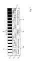
- Fig. 1 shows the basic structure of a process control strip (1) for direct exposure of printing plates by means of an imagesetter (computer-to-plate).
- the process control strip (1) is during the direct exposure of the printing plate in the imagesetter outside of that intended for the information to be exposed Area of the printing plate exposed on the printing plate and together with the information developed in a development station.
- the exposed and developed process control strip (1) is used for visual control and setting of the process parameters such as the intensity of the exposure beam and the development temperature and / or the regeneration rates in the development station.
- the process control strip (1) basically consists of three in the direction of the larger one Extension of the process control strip (1) extending parallel to each other arranged strips, namely a setpoint strip (2), an actual value strip (3) and a display strip (4).
- the setpoint strip (2) is a stepped tonal value wedge for example 16 reference levels from 0% to 100%.
- the reference tone values of the tone value wedge are largely process-independent, i.e. they change only insignificant in the case of fluctuations in process parameters.
- a setpoint range can be set within the tone value wedge of the setpoint strip (1) (5) the at least one reference tone level as the setpoint tolerance range contains that in the exposure and development process on the Pressure plate should be reached.
- the reference tone levels of the Tone value wedge appropriately selected such that the desired setpoint range (5) lies in the middle area of the process control strip (1).
- a tone value wedge can also be used with continuously changing reference tone values.
- the tone value wedge of the setpoint strip (2) is a line grid with perpendicular to Extension of the process control strip (1) oriented lines (6) formed are composed of individual pixels during exposure.
- the reference tone values of the tonal value wedge are due to the ratio of line width to line interval of the line grid defined.
- the lines (6) of the tone value wedge represent rough signal elements The size of the coarse signal elements changes with fluctuations the process parameters are only minor because of the process-dependent changes the pixel sizes essentially only in the direction of the lines on the side Edges of the lines (6) lead to negligible tonal value changes, whereby the reference tone values of the setpoint strip (2) are essentially process-independent are.
- the structure of the line grid of the setpoint strip (2) is due to the resolving power of the human eye and should be chosen that the integrating effect regarding a homogeneous impression is not lost goes.
- a favorable value for the line spacing in the line grid lies in the range 10 to 16 times the value of the pixel diameter by the addressing can be set when generating the halftone dot.
- the actual value strip (3) running parallel to the setpoint strip (2) is finely screened, for example with 333 lines / cm, and represents a highly process-dependent, but represents a uniform tonal value within the actual value strip (3).
- the actual value strip (3) consists of a plurality of fine arranged in a grid Halftone dots, each halftone dot within a grid of the grid is composed of individual exposed pixels during the exposure.
- the sum of the exposed pixel areas or the halftone dot size within one Grid mesh based on the total area of the grid mesh determines the exposed tonal value.
- the exposed pixels or those composed of the exposed pixels Grid points within the actual value strip (3) form fine signal elements, whose size changes with fluctuations in the process parameters, which creates process-dependent tonal value changes.
- each halftone dot is more appropriate Way from a comparatively large number of within a grid of the available pixels of the grid are exposed, for example from 2 x 2 exposed pixels within a 3 x 3 pixel grid.
- a process-dependent change in pixel size thus brings about a comparable one large change in the percentage of the total area of a Grid mesh, so that changes in pixel size due to fluctuations the process parameter changes the tonal value within the actual value strip (3) arise.
- the structure of the grid in the actual value strip (3) with regard to the size of the grid mesh, the dot size and dot shape is determined by the resolution limited to the printing plate to be exposed and is therefore of the plate type and additional also dependent on addressing when generating raster points. practical Values are 3 to 5 times the addressing for the side length of one square grid grid.
- Each pixel size exposed on the actual value strip (3) of the process control strip (1) or dot size thus represents one achieved in the exposure process Tone value that corresponds to a reference tone value of the tone value wedge of the setpoint strip (2) matches.
- the tonal value of the actual value strip changes (3) while the tonal values of the tonal value wedge in the setpoint strip (2) of the process control strip (1) remain practically stable.
- the tonal values are matched at another point on the process control strip (1).
- the process control strip (1) is parallel to the setpoint strip (2) and the Actual value strips (3) extending display strips (4) in the longitudinal direction of the strip Display fields arranged one behind the other and labeled with symbols (7) is divided.
- a display field (7a) e.g. B. with the label "setpoint reached” or “correct exposure” while the neighboring display fields (7b, 7c) e.g. B. with the inscription “falling below setpoint” or “too little exposure” or “setpoint exceeded” or “too much exposure” are provided.
- Fig. 3 shows a process control strip (1) simulated as a contone pressure Reproduction of the real optical impression for printing reasons not is possible, the real optical impression in Fig. 3 is by means of a contone print the process control strip (1) simulated.
- the visual tonal value comparison thus advantageously provides a continuous one Statement about process stability.
- the distance between the "coarseness" of the line grid the tone value wedge in the setpoint strip (2) and the "fineness" of Dot grid in the actual value strip (3) determines the sensitivity of the control process.
- the calibration and control procedure with the help of the process control strip (1) enables a highly sensitive quality assessment of the overall process of direct exposure and development of printing plates.
- the high sensitivity poses in particular the increased quality requirements that are certain when exposing Printing plates with frequency-modulated grids exist.
- Fig. 4 shows a basic block diagram of a device for direct exposure of printing plates, in particular offset printing plates.
- the facility exists essentially a raster image processor (8), simply called RIP, a plate imager (9) and a plate development station (10).
- One sheet to be exposed on the printing plate and the one next to the sheet Process control strips (1) to be exposed are, for example, in an electronic Assembly station assembled according to an imposition program.
- the one there PostScript image data obtained are then processed in a raster image processor (8) interpreters included in a display list.
- the raster generator also contained in the raster image processor (8) Display list after a raster function in corresponding control signal values in Form of a bitmap for switching on and off pixel by pixel in an exposure unit of the platesetter (9) converted exposure beam.
- the platesetter (9) takes the pixel-by-line exposure of the printing plate (11) before.
- the control signal values of the bitmap determine during plate exposure, which pixels are exposed as parts of the halftone dots on the printing plate (11) or not exposed.
- the grid function defines the size of the grid points depending on the tonal values to be recorded.
- the exposure beam is, for example, a laser beam, which by means of the control signal values controlled modulator is switched on and off.
- a platesetter (9) can, for example, the "Gutenberg" platesetter from Linotype-Hell AG can be used.
- the exposed plate is on the printing plate (11) exposed in the platesetter (9) Printing sheet (12) and the process control strip exposed outside the printing sheet (12) (1) visible.
- a CTX printing plate for example, can be used as the printing plate (11) from Polychrome can be used.
- the exposed printing plate (11) is developed in the plate development station (10).
- the process control strip (1) on the exposed and developed printing plate (10 ') is then used for visual control of the exposure process and for adjustment the process parameter used.
Landscapes
- Physics & Mathematics (AREA)
- General Physics & Mathematics (AREA)
- Exposure And Positioning Against Photoresist Photosensitive Materials (AREA)
- Photographic Processing Devices Using Wet Methods (AREA)
- Control Of Exposure In Printing And Copying (AREA)
- Photographic Developing Apparatuses (AREA)
- Preparing Plates And Mask In Photomechanical Process (AREA)
Description
- Fig. 1
- einen prinzipiellen Aufbau eines Prozeßkontrollstreifens für die Direktbelichtung von Druckplatten mittels eines Belichters,
- Fig. 2
- ein praktisches Ausführungsbeispiel für einen Prozeßkontrollstreifen,
- Fig. 3
- einen als Contone-Druck simulierten Prozeßkonztollstreifen und
- Fig. 4
- ein prinzipielles Blockschaltbild einer Einrichtung zur direkten Belichtung von Druckplatten.
Claims (15)
- Prozeßkontrollstreifen zur visuellen Kontrolle eines Belichtungsprozesses für ein Aufzeichnungsmaterial, welcher grobe Signalelelemente, deren Größe bei Prozeßschwankungen im wesentlichen konstant ist, und feine Signalelemente, deren Größe sich bei Prozeßschwankungen ändert, aufweist, dadurch gekennzeichnet, daßdas Aufzeichnungsmaterial eine Druckplatte ist.ein sich in Richtung der größeren Ausdehnung des Prozeßkontrollstreifens (1) erstreckender erster Streifen (2) einen Tonwertkeil mit sich in Streifenrichtung ändernden, prozeßunabhängigen Referenztonwerten als grobe Signalelemente aufweist,ein parallel zum ersten Streifen (2) verlaufender zweiter Streifen (3) ein Raster mit feinen Rasterpunkten als feine Signalelemente aufweist, das im zweiten Streifen (3) einen gleichmäßigen, stark prozeßabhängigen Tonwert repräsentiert, und
- Prozeßkontrollstreifen nach Anspruch 1, dadurch gekennzeichnet, daß der Tonwertkeil des ersten Streifens (2) als Linienraster ausgebildet sind.
- Prozeßkontrollstreifen nach Anspruch 2, dadurch gekennzeichnet, daß die Linien (6) des Linienrasters im ersten Streifen (2) senkrecht zur Streifenrichtung orientiert sind.
- Prozeßkontrollstreifen nach einem der Ansprüche 2 oder 3, dadurch gekennzeichnet, daß die Linien (6) des Linienrasters im ersten Streifen (2) und die Rasterpunkte im zweiten Streifen (3) aus aufgezeichneten Pixeln zusammengesetzt sind.
- Prozeßkontrollstreifen nach einem der Ansprüche 1 bis 4, dadurch gekennzeichnet, daß jeder Rasterpunkt innerhalb einer Rastermasche des Rasters des zweiten Streifens (3) aus einer großen Anzahl der innerhalb der Rastermasche zur Verfügung stehenden Pixel belichtet wird.
- Prozeßkontrollstreifen nach Anspruch 5, dadurch gekennzeichnet, daß jede Rastermasche aus 3 x 3 Pixeln besteht und jeder Rasterpunkt innerhalb der Rastermasche aus 2 x 2 Pixeln belichtet wird.
- Prozeßkontrollstreifen nach einem der Ansprüche 1 bis 6, dadurch gekennzeichnet, daß im Tonwertkeil des ersten Streifens (2) ein Sollwert-Bereich (5) definierbar ist, der mindestens einen im Belichtungsprozeß gewünschten Referenztonwert zum visuellen Vergleich mit dem im Belichtungsprozeß erreichten Tonwert des zweiten Streifens (3) umfaßt.
- Prozeßkontrollstreifen nach einem der Ansprüche 1 bis 7, dadurch gekennzeichnet, daß die Referenztonwerte des Tonwertkeiles im ersten Streifen (2) derart gewählt sind, daß der definierte Sollwert-Bereich (5) im mittleren Bereich des Prozeßkontrollstreifens (1) liegt.
- Prozeßkontrollstreifen nach einem der Ansprüche 1 bis 8, dadurch gekennzeichnet, daß der Prozeßkontrollstreifen (1) einen zum ersten und zweiten Streifen (2, 3) parallel verlaufenden dritten Streifen (4) zur Anzeige des Grades einer Tonwertübereinstimmung zwischen den Referenztonwerten des ersten Streifens (2) und den im Belichtungsprozeß erreichten Tonwerten des zweiten Streifens (3) aufweist.
- Prozeßkontrollstreifen nach Anspruch 9, dadurch gekennzeichnet, daß der dritte Streifen (4) in in Streifenrichtung hintereinander angeordnete Anzeige-Felder (7) unterteilt ist, die den jeweiligen Grad der Tonwertübereinstimmung durch Symbole anzeigen.
- Prozeßkontrollstreifen nach Anspruch 9 und 10, dadurch gekennzeichnet, daßdem definierten Sollwert-Bereich (5) des ersten Streifens (2) ein Anzeige-Feld (7a) im dritten Streifen (4) mit dem Symbol "Sollwert erreicht " zugeordnet ist unddie benachbarten Anzeige-Felder (7b, 7c) des dritten Streifens (4) mit den Symbolen "Sollwertüberschreitung" bzw. "Sollwertunterschreitung" versehen sind.
- Verfahren zur Belichtung eines Prozeßkontrollstreifens dadurch gekennzeichnet, daß der Prozeßkontrollstreifen ein Prozeßkontrollstreifen nach einem der Ansprüche 1-11 ist und dieser (1) pixel- und zeilenweise direkt auf eine Druckplatte (11) belichtet wird.
- Verfahren nach Anspruch 12, dadurch gekennzeichnet, daß die Belichtung des Prozeßkontrollstreifens (1) gleichzeitig mit der punkt- und zeilenweisen Belichtung der Druckplatte (11) durchgeführt wird.
- Verfahren nach Anspruch 12 oder 13, dadurch gekennzeichnet, daß der Prozeßkontrollstreifen (1) als Post-Script-Daten generiert wird.
- Verfahren nach einem der Ansprüche 12 bis 14 dadurch gekennzeichnet, daß der Prozeßkontrollstreifen (1) bei der punkt- und zeilenweisen Belichtung der Druckplatte (11) derart orientiert ist, daß die Linien (6) des Linienrasters im ersten Streifen (2) in Zeilenrichtung verlaufen.
Applications Claiming Priority (3)
| Application Number | Priority Date | Filing Date | Title |
|---|---|---|---|
| DE19507665 | 1995-03-04 | ||
| DE19507665A DE19507665A1 (de) | 1995-03-04 | 1995-03-04 | Verfahren zur Kalibrierung und Kontrolle einer Belichtung und Belichtungs-Kontrollstreifen |
| PCT/DE1996/000363 WO1996027821A1 (de) | 1995-03-04 | 1996-03-02 | Prozesskontrollstreifen und verfahren zur aufzeichnung |
Publications (2)
| Publication Number | Publication Date |
|---|---|
| EP0759192A1 EP0759192A1 (de) | 1997-02-26 |
| EP0759192B1 true EP0759192B1 (de) | 2003-01-02 |
Family
ID=7755685
Family Applications (1)
| Application Number | Title | Priority Date | Filing Date |
|---|---|---|---|
| EP96903928A Expired - Lifetime EP0759192B1 (de) | 1995-03-04 | 1996-03-02 | Prozesskontrollstreifen und verfahren zur aufzeichnung |
Country Status (5)
| Country | Link |
|---|---|
| US (1) | US5748331A (de) |
| EP (1) | EP0759192B1 (de) |
| JP (1) | JP2888992B2 (de) |
| DE (2) | DE19507665A1 (de) |
| WO (1) | WO1996027821A1 (de) |
Cited By (1)
| Publication number | Priority date | Publication date | Assignee | Title |
|---|---|---|---|---|
| EP1832924A1 (de) * | 2006-03-10 | 2007-09-12 | Heidelberger Druckmaschinen AG | Prozesskontrollstreifen und Verfahren zur Aufzeichnung |
Families Citing this family (13)
| Publication number | Priority date | Publication date | Assignee | Title |
|---|---|---|---|---|
| JPH10104761A (ja) * | 1996-10-02 | 1998-04-24 | Noritsu Koki Co Ltd | 面光源の自動補正方法および自動補正装置 |
| EP0847858B1 (de) * | 1996-12-11 | 2002-07-24 | Agfa-Gevaert | Sichtbarer Kontrollstreifen für Abbildungsmedien |
| DE19825828A1 (de) * | 1998-06-10 | 1999-12-16 | Agfa Gevaert Ag | Kontrollelement für ein strahlungsempfindliches Aufzeichnungsmaterial und Verfahren zum Bestimmen der Belichtungsenergie für ein strahlungsempfindliches Aufzeichnungsmaterial mittels eines Kontrollelements |
| GB0012457D0 (en) * | 2000-05-22 | 2000-07-12 | Priest Mark | Calibrating printing machines |
| DE60236099D1 (de) * | 2001-10-15 | 2010-06-02 | Toppan Printing Co Ltd | Druckverfahren, druckerzeugnisse und drucksteuerung |
| GB2392994A (en) * | 2002-05-30 | 2004-03-17 | Medivance Instr Ltd | Apparatus and method for monitoring the efficacy of an X-ray or photographic development process |
| FR2865293B1 (fr) * | 2004-01-20 | 2006-03-31 | Atmel Nantes Sa | Microcontroleur a convertisseur numerique analogique synchronise. |
| DE102004013290A1 (de) * | 2004-03-18 | 2005-09-29 | Heidelberger Druckmaschinen Ag | Visuelle Kontrolleinrichtung für belichtete Druckplatten |
| WO2008053719A1 (en) * | 2006-10-31 | 2008-05-08 | Konica Minolta Medical & Graphic, Inc. | Plate making method, printing plate image output device, image editing device and printing plate image output system |
| US8570340B2 (en) | 2008-03-31 | 2013-10-29 | Konica Minolta Laboratory U.S.A., Inc. | Systems and methods for data compression |
| US8699042B2 (en) * | 2008-06-12 | 2014-04-15 | Konica Minolta Laboratory U.S.A., Inc. | Systems and methods for multi-mode color blending |
| DE102013010970A1 (de) | 2013-07-01 | 2015-01-08 | Heidelberger Druckmaschinen Ag | Speziell gerastertes Graumessfeld |
| CN106054372B (zh) * | 2016-07-24 | 2018-04-03 | 哈尔滨理工大学 | 一种对比度连续调节光栅和对比度连续调节方法 |
Family Cites Families (13)
| Publication number | Priority date | Publication date | Assignee | Title |
|---|---|---|---|---|
| CA1012822A (en) * | 1972-11-13 | 1977-06-28 | American Hoechst Corporation | Test film and method of using same |
| US4004923A (en) * | 1973-11-02 | 1977-01-25 | American Hoechst Corporation | Method of using a test film to measure developer activity |
| DE2426840C3 (de) * | 1974-06-04 | 1978-04-13 | Deutsche Forschungsgesellschaft Fuer Druck Und Reproduktionstechnik E.V., 8000 Muenchen | Meßstreifen |
| JPS6024461B2 (ja) * | 1976-11-22 | 1985-06-13 | 富士写真フイルム株式会社 | ステツプタブレツト |
| DE2905156C2 (de) * | 1979-02-10 | 1983-04-14 | Gerhard 8960 Kempten Werner | Testfilm zur Bewertung der Randungschärfe und Schwärzung von Rasterpunkten bei Kopiervorlagen (Rasterpoitive und Rasternegative) |
| JPS58202445A (ja) * | 1982-01-18 | 1983-11-25 | Dainippon Screen Mfg Co Ltd | 写真フイルムの現像液管理方法及びこの方法の実施に使用されるコントロ−ルストリツプ |
| JPS5987050U (ja) | 1982-12-01 | 1984-06-12 | 富士写真フイルム株式会社 | ステツプタブレツト |
| US4504141A (en) * | 1983-07-07 | 1985-03-12 | Noby Yamakoshi | System for making matched backgrounds |
| DE3409856A1 (de) * | 1984-03-17 | 1985-09-19 | Gerhard 8960 Kempten Werner | Kontrollelement fuer bilduebertragungsverfahren, insbesondere fuer die reproduktions- und drucktechnik |
| DE4203237A1 (de) * | 1992-02-05 | 1993-08-19 | Ralf Dannapfel | Verfahren und vorrichtung zur photographischen belichtungssteuerung |
| DE4303081C2 (de) * | 1992-02-18 | 1995-07-13 | Hell Ag Linotype | Verfahren und Einrichtung zur Belichtungs-Kalibrierung von Aufzeichnungsgeräten |
| DE4316825C2 (de) * | 1993-05-19 | 1994-06-30 | Axel Ritz | Kontrollstreifen zur Überwachung der Übertragungseigenschaften und Tonwertveränderungen photopolymerer Druckplatten |
| DE4338975A1 (de) * | 1993-11-15 | 1995-05-18 | Fogra Forschungsgesellschaft D | Kontrollfeld sowie Verfahren und Vorrichtung zu seiner Herstellung |
-
1995
- 1995-03-04 DE DE19507665A patent/DE19507665A1/de not_active Withdrawn
-
1996
- 1996-03-02 DE DE59610020T patent/DE59610020D1/de not_active Expired - Lifetime
- 1996-03-02 EP EP96903928A patent/EP0759192B1/de not_active Expired - Lifetime
- 1996-03-02 US US08/732,299 patent/US5748331A/en not_active Expired - Lifetime
- 1996-03-02 JP JP8526526A patent/JP2888992B2/ja not_active Expired - Fee Related
- 1996-03-02 WO PCT/DE1996/000363 patent/WO1996027821A1/de not_active Ceased
Cited By (2)
| Publication number | Priority date | Publication date | Assignee | Title |
|---|---|---|---|---|
| EP1832924A1 (de) * | 2006-03-10 | 2007-09-12 | Heidelberger Druckmaschinen AG | Prozesskontrollstreifen und Verfahren zur Aufzeichnung |
| DE102006011140A1 (de) * | 2006-03-10 | 2007-09-13 | Heidelberger Druckmaschinen Ag | Prozesskontrollstreifen und Verfahren zur Aufzeichnung |
Also Published As
| Publication number | Publication date |
|---|---|
| JPH09505678A (ja) | 1997-06-03 |
| DE59610020D1 (de) | 2003-02-06 |
| JP2888992B2 (ja) | 1999-05-10 |
| US5748331A (en) | 1998-05-05 |
| WO1996027821A1 (de) | 1996-09-12 |
| DE19507665A1 (de) | 1996-09-05 |
| EP0759192A1 (de) | 1997-02-26 |
Similar Documents
| Publication | Publication Date | Title |
|---|---|---|
| EP0759192B1 (de) | Prozesskontrollstreifen und verfahren zur aufzeichnung | |
| DE69212539T2 (de) | Verfahren und Vorrichtung zur Erzeugung eines Kontrollstreifens | |
| DE19506425B4 (de) | Offsetdruckverfahren | |
| DE19723618B4 (de) | Maske und Verfahren zu ihrer Herstellung zum Belichten von flexographischen Platten | |
| DE69416029T2 (de) | Verfahren zur Korrektur von Halbtonpunktbilddaten und Bildverarbeitungsgerät das diese Korrektur verwendet | |
| DE3830732A1 (de) | Verfahren zur ueberwachung und/oder regelung der feuchtmittelfuehrung bei einer offset-druckmaschine | |
| EP0401241B1 (de) | Verfahren zur erfassung von druckflächenbedeckungsdaten | |
| DE69614758T2 (de) | Verfahren und Vorrichtung zum Aufzeichnen steroeskopischer Bilder auf vorbeschichtetem Linsenrastermaterial | |
| DE19924143C2 (de) | Abschattungskorrektureinrichtung und Verfahren für eine Abschattungskorrektur eines Bildaufnahmesystems | |
| EP0032908A1 (de) | Verfahren zur autotypischen tonwertzerlegung. | |
| DE2627247C2 (de) | Scanner zur Aufzeichnung von Halbtonrasterpunkten, die aus linienförmig belichteten Bereichen aufgebaut sind | |
| DE2401672C3 (de) | Vorrichtung zur Kontrolle der Bildqualität eines in einem Reproduktions- und Druckverfahren zu verarbeitenden Bildes und Verfahren zur Herstellung der Vorrichtung | |
| DE60003325T2 (de) | Vorhersage und verhinderung von problemen mit offsetdruckmaschinen | |
| DE69303809T2 (de) | Verfahren zur Herstellung lithographischer Druckformen | |
| DE3789774T2 (de) | Verfahren zur Erzeugung eines Halbtonrasters. | |
| DE69733133T2 (de) | Auflösungsverbesserung bei einem Bildsetzer | |
| DE69628539T2 (de) | Einstellung der Punktgrösse für Laserdrucker | |
| DE69714197T2 (de) | Sichtbarer Kontrollstreifen für Abbildungsmedien | |
| DE4303081C2 (de) | Verfahren und Einrichtung zur Belichtungs-Kalibrierung von Aufzeichnungsgeräten | |
| EP0990343B1 (de) | Verfahren zur digitalen rasterung von halbtonbildern mit rastern beliebiger rasterweiten und rasterwinkel | |
| EP1580980B1 (de) | Verfahren und Druckplatte zum Abgleichen der Belichtungsköpfe in einem Belichter für Druckvorlagen | |
| EP2211294A1 (de) | Verfahren zur Korrektur der Schrägaufzeichnung bei der Belichtung von Druckvorlagen | |
| DE10201918B4 (de) | Verfahren zur Bestimmung der Flächendeckung von Druckplatten | |
| DE60104192T2 (de) | Verfahren und vorrichtung zur steuerung der lichtintensität in verbindung mit der belichtung von lichtempfindlichem material | |
| EP1832924B1 (de) | Prozesskontrollstreifen und Verfahren zur Aufzeichnung |
Legal Events
| Date | Code | Title | Description |
|---|---|---|---|
| PUAI | Public reference made under article 153(3) epc to a published international application that has entered the european phase |
Free format text: ORIGINAL CODE: 0009012 |
|
| AK | Designated contracting states |
Kind code of ref document: A1 Designated state(s): DE FR GB |
|
| 17P | Request for examination filed |
Effective date: 19970312 |
|
| RAP1 | Party data changed (applicant data changed or rights of an application transferred) |
Owner name: HEIDELBERGER DRUCKMASCHINEN AKTIENGESELLSCHAFT |
|
| GRAG | Despatch of communication of intention to grant |
Free format text: ORIGINAL CODE: EPIDOS AGRA |
|
| GRAG | Despatch of communication of intention to grant |
Free format text: ORIGINAL CODE: EPIDOS AGRA |
|
| GRAH | Despatch of communication of intention to grant a patent |
Free format text: ORIGINAL CODE: EPIDOS IGRA |
|
| 17Q | First examination report despatched |
Effective date: 20020627 |
|
| GRAH | Despatch of communication of intention to grant a patent |
Free format text: ORIGINAL CODE: EPIDOS IGRA |
|
| GRAA | (expected) grant |
Free format text: ORIGINAL CODE: 0009210 |
|
| AK | Designated contracting states |
Kind code of ref document: B1 Designated state(s): DE FR GB |
|
| REG | Reference to a national code |
Ref country code: GB Ref legal event code: FG4D Free format text: 20030102:NOT ENGLISH |
|
| REF | Corresponds to: |
Ref document number: 59610020 Country of ref document: DE Date of ref document: 20030206 Kind code of ref document: P |
|
| GBT | Gb: translation of ep patent filed (gb section 77(6)(a)/1977) |
Effective date: 20030428 |
|
| ET | Fr: translation filed | ||
| PLBE | No opposition filed within time limit |
Free format text: ORIGINAL CODE: 0009261 |
|
| STAA | Information on the status of an ep patent application or granted ep patent |
Free format text: STATUS: NO OPPOSITION FILED WITHIN TIME LIMIT |
|
| 26N | No opposition filed |
Effective date: 20031003 |
|
| PGFP | Annual fee paid to national office [announced via postgrant information from national office to epo] |
Ref country code: GB Payment date: 20130326 Year of fee payment: 18 Ref country code: DE Payment date: 20130331 Year of fee payment: 18 |
|
| PGFP | Annual fee paid to national office [announced via postgrant information from national office to epo] |
Ref country code: FR Payment date: 20130419 Year of fee payment: 18 |
|
| REG | Reference to a national code |
Ref country code: DE Ref legal event code: R119 Ref document number: 59610020 Country of ref document: DE |
|
| GBPC | Gb: european patent ceased through non-payment of renewal fee |
Effective date: 20140302 |
|
| REG | Reference to a national code |
Ref country code: FR Ref legal event code: ST Effective date: 20141128 |
|
| REG | Reference to a national code |
Ref country code: DE Ref legal event code: R119 Ref document number: 59610020 Country of ref document: DE Effective date: 20141001 |
|
| PG25 | Lapsed in a contracting state [announced via postgrant information from national office to epo] |
Ref country code: GB Free format text: LAPSE BECAUSE OF NON-PAYMENT OF DUE FEES Effective date: 20140302 Ref country code: FR Free format text: LAPSE BECAUSE OF NON-PAYMENT OF DUE FEES Effective date: 20140331 Ref country code: DE Free format text: LAPSE BECAUSE OF NON-PAYMENT OF DUE FEES Effective date: 20141001 |