EP0758036B1 - Verfahren zum Einbringen eines Bodenankers und entsprechender Bodenanker - Google Patents
Verfahren zum Einbringen eines Bodenankers und entsprechender Bodenanker Download PDFInfo
- Publication number
- EP0758036B1 EP0758036B1 EP96202181A EP96202181A EP0758036B1 EP 0758036 B1 EP0758036 B1 EP 0758036B1 EP 96202181 A EP96202181 A EP 96202181A EP 96202181 A EP96202181 A EP 96202181A EP 0758036 B1 EP0758036 B1 EP 0758036B1
- Authority
- EP
- European Patent Office
- Prior art keywords
- pipe sleeve
- anchor body
- ground
- extension rod
- anchor
- Prior art date
- Legal status (The legal status is an assumption and is not a legal conclusion. Google has not performed a legal analysis and makes no representation as to the accuracy of the status listed.)
- Expired - Lifetime
Links
- 238000000034 method Methods 0.000 title claims abstract description 12
- 239000004570 mortar (masonry) Substances 0.000 description 4
- 238000004873 anchoring Methods 0.000 description 3
- 229910000831 Steel Inorganic materials 0.000 description 1
- 238000010276 construction Methods 0.000 description 1
- 230000000694 effects Effects 0.000 description 1
- 239000011796 hollow space material Substances 0.000 description 1
- 239000002689 soil Substances 0.000 description 1
- 239000007787 solid Substances 0.000 description 1
- 230000000087 stabilizing effect Effects 0.000 description 1
- 239000010959 steel Substances 0.000 description 1
- 230000007704 transition Effects 0.000 description 1
- 238000004804 winding Methods 0.000 description 1
Images
Classifications
-
- E—FIXED CONSTRUCTIONS
- E02—HYDRAULIC ENGINEERING; FOUNDATIONS; SOIL SHIFTING
- E02D—FOUNDATIONS; EXCAVATIONS; EMBANKMENTS; UNDERGROUND OR UNDERWATER STRUCTURES
- E02D5/00—Bulkheads, piles, or other structural elements specially adapted to foundation engineering
- E02D5/74—Means for anchoring structural elements or bulkheads
- E02D5/80—Ground anchors
Definitions
- the invention relates to a method as defined in the first part of claim 1.
- Such a method is well-known and is applied e.g. for stabilizing permanent or temporary sheet-pile walls that are driven into the ground at a distance from the anchor body.
- an anchor body having a hollow core and screw blades is used and after this anchor body has been screwed into the ground a settable mortar is introduced.
- the mortar is pressed through the extension tube and the hollow space of the anchor body into the earth between the screw blade turns to form together with said earth a solid mass, in which the anchor body becomes fixedly anchored.
- the extension tubes form a permanent part of the anchor and are attached to the sheet-pile wall with the proximal end extending through a hole in the sheet-pile wall and with the intermediary of an anchoring support.
- the introduction of the ground anchors into the ground is started only after the sheet-pile wall is completed.
- the introduction of the individual sheet-piles involves powerful vibrations, which are transmitted through the earth. If one would start the introduction of the ground anchors, while continuing driving or vibrating further sheet-piles into the ground, these vibrations would prevent an effective setting process of the settable mortar, so that the required resistance to pull out would not be obtained.
- the effect of the improved method is, that when rotating the pipe sleeve about the stationary extension rod the line will be gradually pulled inwardly and downwardly through the interior of the pipe sleeve and upon leaving through the guiding eyelet wind itself to a coil on the proximal end portion of the anchor body and/or the distal end portion of the extension rod connected thereto.
- This causes the anchor body to increase both in mass and in diameter, resulting in a corresponding improvement of the resistance to pull out.
- the soil around the coil is displaced and compressed by said coil while being wound.
- ground anchors By placing a ground anchor into the ground at the location of each sheet-pile use can be made of ground anchors having a relatively low tensile-strength, while it is no longer required to place supporting beams along the outer side of the sheet-pile wall, as is required when using ground anchors the mutual spacing of which is many times larger than the width of a sheet-pile.
- US-A 2 603 319 discloses an auger type ground anchor, with which the distal end of a line is fastened to a laterally extending eyelet of a sleeve that is rotatably mounted about either an upper smooth section of the shaft of the anchor body or about an extension of the latter.
- the invention also relates to a ground anchor as defined in the first part of claim 2, as is well-known per se.
- the improved ground anchor according to the invention is characterized by the features defined in the second part of claim 2.
- Claims 3 and 4 define features of a preferred embodiment of the anchor according to the invention.
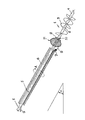
- the anchor shown in the drawing has to be driven into the ground under an elevational angle ⁇ of e.g. 25-40°. It comprises an anchor body 1 in the form of a core rod 2 that is provided with a screw blade 3 in a well-known manner and ends at its distal end into a bevelled frog 4.
- An extension rod 5 is connected to the proximal end of the anchor body 1.
- the extension rod is indicated as integrally formed with the core rod 2.
- the extension rod 5 is surrounded by a pipe sleeve 6, that has a guiding eyelet 7 at its distal end.
- a flange 8 is provided on the core rod 2 at the transition between said core rod and the extension rod 5.
- the distal end of a steel wire cable 9 is anchored on the side of the flange that is turned away from the frog 4.
- the cable 9 extends from the anchoring point 10 straight through the guiding eyelet 7 and the clearance space between the exten-sion rod 5 and the pipe sleeve 6 towards the anchor end turned away from the frog 4.
- the anchor is screwed into the ground in a well-known manner, under the desired elevational angle ⁇ , by rotating the extension rod 5 and the pipe sleeve 6 jointly in the arrow direction A.
- the extension rod 5 is disconnected from the driving device (not shown) positioned above ground level after which the pipe sleeve is further rotated around the stationary extension rod 5.
- This causes the line 9 to be gradually pulled through the alter tube 6 downwardly, while being guided through the guiding eyelet 7, and to wind itself to a coil 11 that bears against the flange 10.
- the tube 6 is stopped and locked against further rotation, after which the anchor may be connected with its upper projecting end to the structure to be stabalized.
Landscapes
- Engineering & Computer Science (AREA)
- Structural Engineering (AREA)
- Life Sciences & Earth Sciences (AREA)
- General Life Sciences & Earth Sciences (AREA)
- Mining & Mineral Resources (AREA)
- Paleontology (AREA)
- Civil Engineering (AREA)
- General Engineering & Computer Science (AREA)
- Piles And Underground Anchors (AREA)
- Conveying And Assembling Of Building Elements In Situ (AREA)
- Joining Of Building Structures In Genera (AREA)
Claims (4)
- Verfahren zum Einbringen eines Erdankers in den Boden, das darin besteht, einen länglichen Ankerkörper (1) unter Verwendung einer Verlängerungsstange (5) in den Boden zu schrauben, wobei die Verlängerungsstange mit dem proximalen Ende des Ankerkörpers verbunden ist und dann gedreht wird, bis der Ankerkörper eine gewünschte Tiefe erreicht hat, gekennzeichnet durch die zusätzlichen Schritte, die darin bestehen,ein Ende des ausreichend zugkräftigen Seils (9) an eine vom proximalen Ende des Ankerkörpers beabstandete Stelle an den Ankerkörper zu befestigen,ein Rohr (6) über die Verlängerungsstange zu schieben, wobei das Seil durch eine neben dem distalen Ende des Rohres befestigte Öse (7) hindurchgeführt und entlang dieses Rohres nach oben geführt wird,die Verlängerungsstange und das Rohr gemeinsam zu drehen, bis der Ankerkörper die gewünschte Tiefe erreicht hat,die Verlängerungsstange festzuhalten, um eine weitere Drehung derselben zu verhindern, bei gleichzeitiger weiterer Drehung des Rohres, so dass das Seil allmählich nach unten durch das Rohr herausgezogen wird und sich am proximalen Endstück des Ankerkörpers und/oder am distalen Endstück der Verlängerungsstange zu einer Rolle aufwickelt.
- Erdanker zur Verwendung nach dem Verfahren gemäß Anspruch 1, bestehend ausdadurch gekennzeichnet, dass ein Ende des ausreichend zugkräftigen Seils (9) mit dem Ankerkörper an eine vom proximalen Ende des Ankerkörpers beabstandete Stelle an den Ankerkörper verbunden ist, und dass die Verlängerungsstange von einem Rohr (6) mit einem distalen und einem proximalen Ende umgeben ist, wobei das Rohr an seinem distalen Ende mit einer Führungsöse (7) versehen ist, wobei das Seil durch die Führungsöse hindurch und entlang des Rohres in Richtung auf das proximale Ende desselben und darüber hinaus geführt wird, und wobei das Rohr auch mit den Drehmitteln verbindbar ist, so dass es wahlweise durch die Drehmittel entweder allein oder in Verbindung mit der Verlängerungsstange gedreht werden kann, wobei die Führung des Seils derart ist, dass, wenn nur das Rohr gedreht wird, das Seil durch das Rohr nach unten herausgezogen wird und sich am proximalen Endstück des Ankerkörpers und/oder am distalen Endstück der Verlängerungsstange zu einer Rolle aufwickelt.einem länglichen Ankerkörper (1) mit einem distalen und einem proximalen Ende, undeiner Verlängerungsstange (5) mit einem distalen Ende, das mit dem proximalen Ende des Ankerkörpers verbunden ist und mit einem proximalen Ende, das mit Drehmitteln zum Einbringen des Ankerkörpers in den Boden verbindbar ist,
- Erdanker nach Anspruch 2, dadurch gekennzeichnet, dass der Ankerkörper (1) einen Stützflansch an der Verbindungsstelle mit dem Seil aufweist.
- Erdanker nach den Ansprüchen 2-3, dadurch gekennzeichnet, dass das ausreichend zugkräftige Seil (9) durch den Zwischenraum zwischen dem Rohr und der Verlängerungsstange hindurch geführt wird.
Applications Claiming Priority (2)
| Application Number | Priority Date | Filing Date | Title |
|---|---|---|---|
| NL1000951A NL1000951C2 (nl) | 1995-08-08 | 1995-08-08 | Werkwijze voor het aanbrengen van een trekanker in de bodem, alsmede daarbij te gebruiken anker. |
| NL1000951 | 1995-08-08 |
Publications (2)
| Publication Number | Publication Date |
|---|---|
| EP0758036A1 EP0758036A1 (de) | 1997-02-12 |
| EP0758036B1 true EP0758036B1 (de) | 2000-12-27 |
Family
ID=19761418
Family Applications (1)
| Application Number | Title | Priority Date | Filing Date |
|---|---|---|---|
| EP96202181A Expired - Lifetime EP0758036B1 (de) | 1995-08-08 | 1996-08-02 | Verfahren zum Einbringen eines Bodenankers und entsprechender Bodenanker |
Country Status (9)
| Country | Link |
|---|---|
| US (1) | US5927905A (de) |
| EP (1) | EP0758036B1 (de) |
| JP (1) | JPH11510574A (de) |
| AT (1) | ATE198366T1 (de) |
| DE (1) | DE69611332T2 (de) |
| DK (1) | DK0758036T3 (de) |
| ES (1) | ES2154782T3 (de) |
| NL (1) | NL1000951C2 (de) |
| WO (1) | WO1997006311A1 (de) |
Families Citing this family (23)
| Publication number | Priority date | Publication date | Assignee | Title |
|---|---|---|---|---|
| ES2143356B1 (es) * | 1997-01-10 | 2000-12-16 | Codina Juan Vicente Herrero | Dispositivo y procedimiento para la realizacion de pilotajes de cimentacion en maquinas perforadoras. |
| AUPQ929000A0 (en) * | 2000-08-08 | 2000-08-31 | Tristanagh Pty Ltd | Earth anchoring system |
| AU2006252264B2 (en) * | 2000-08-08 | 2008-02-14 | Tristanagh Pty Ltd | Earth Anchoring System |
| US6722085B2 (en) * | 2002-05-17 | 2004-04-20 | Chester L. Pittman | Mobile home tie-down apparatus |
| US6874975B2 (en) | 2002-12-09 | 2005-04-05 | Hilfiker Pipe Company | Soil-nail apparatus and method for constructing soil reinforced earthen retaining walls |
| US6931805B2 (en) * | 2003-02-20 | 2005-08-23 | Gregory Enterprises, Inc. | Post construction alignment and anchoring system and method for buildings |
| US6908258B2 (en) | 2003-07-11 | 2005-06-21 | James E. Timmerman | Methods and apparatus for maintaining seawalls |
| US7517175B2 (en) * | 2003-07-11 | 2009-04-14 | Timmerman James E | Method for maintaining seawalls |
| NL1025013C2 (nl) * | 2003-12-12 | 2005-06-14 | Van Leeuwen Harmelen Bv Geb | Verankeringsamenstel. |
| US8851801B2 (en) | 2003-12-18 | 2014-10-07 | R&B Leasing, Llc | Self-centralizing soil nail and method of creating subsurface support |
| US9273442B2 (en) | 2003-12-18 | 2016-03-01 | R&B Leasing, Llc | Composite self-drilling soil nail and method |
| US20070172315A1 (en) * | 2003-12-18 | 2007-07-26 | Barrett Robert K | Method and Apparatus for Creating Soil or Rock Subsurface Support |
| US20060169313A1 (en) * | 2004-10-18 | 2006-08-03 | Witte Gregory L | Protective structure blanket covering a structure and anchored to the ground |
| NZ553958A (en) * | 2007-03-19 | 2008-04-30 | Miles Edward Moffat | Ground Anchor with cable guiding means for a loop of a winch cable |
| US7731454B1 (en) * | 2007-10-02 | 2010-06-08 | Heli-Crete “Eco-Friendly” Piling Systems, Llc | Method for placing reinforced concrete piling without utilizing a pile driver or an auger |
| US8240957B1 (en) | 2010-06-02 | 2012-08-14 | Heli-Crete “Eco-Friendly” Piling Systems, Llc | Removable coupler apparatus and method for use in placing pilings in the ground |
| US8376661B2 (en) | 2010-05-21 | 2013-02-19 | R&B Leasing, Llc | System and method for increasing roadway width incorporating a reverse oriented retaining wall and soil nail supports |
| US8602689B1 (en) | 2011-06-03 | 2013-12-10 | Heli-Crete “Eco-Friendly” Piling Systems, Llc | Retractable nose cone system and method for forming reinforced concrete pilings and/or an electrical grounding system |
| US9598833B2 (en) | 2011-08-26 | 2017-03-21 | American Piledriving Equipment, Inc. | Apparatus and methods for pipe piling placement with continuous grouting |
| US9650753B2 (en) * | 2011-08-26 | 2017-05-16 | American Piledriving Equipment, Inc. | Apparatus and methods for the placement of pipe piling |
| ITAN20130125A1 (it) * | 2013-07-17 | 2015-01-18 | Landfix S R L | Vite di fondazione comprendente un dispositivo stabilizzatore. |
| US10119291B2 (en) * | 2017-02-17 | 2018-11-06 | James McKinion | Free-standing load support system |
| US12222138B2 (en) | 2021-05-24 | 2025-02-11 | Helical Solar Solutions, LLC | Free-standing load support system |
Family Cites Families (6)
| Publication number | Priority date | Publication date | Assignee | Title |
|---|---|---|---|---|
| US2603319A (en) * | 1952-07-15 | Ground anchor v | ||
| US3628337A (en) * | 1969-09-26 | 1971-12-21 | Fred C Stepanich | Anchorable pile |
| DE8519054U1 (de) * | 1985-07-01 | 1985-08-22 | Rockenfeller KG Befestigungselemente, 5912 Hilchenbach | Vorrichtung zur Verankerung von Zuggliedern in Erdreich |
| US4611446A (en) * | 1985-12-26 | 1986-09-16 | Beavers Allan E | Cable anchoring device |
| CA2088287C (en) * | 1992-02-07 | 2003-05-20 | Masaru Tateyama | Reinforcing block for excavation work and method of construction thereof |
| US5322386A (en) * | 1993-10-12 | 1994-06-21 | Royal Concrete Products, Inc. | Ground anchor device |
-
1995
- 1995-08-08 NL NL1000951A patent/NL1000951C2/nl not_active IP Right Cessation
-
1996
- 1996-08-02 AT AT96202181T patent/ATE198366T1/de not_active IP Right Cessation
- 1996-08-02 DE DE69611332T patent/DE69611332T2/de not_active Expired - Fee Related
- 1996-08-02 WO PCT/NL1996/000315 patent/WO1997006311A1/en not_active Ceased
- 1996-08-02 ES ES96202181T patent/ES2154782T3/es not_active Expired - Lifetime
- 1996-08-02 DK DK96202181T patent/DK0758036T3/da active
- 1996-08-02 US US09/000,475 patent/US5927905A/en not_active Expired - Fee Related
- 1996-08-02 EP EP96202181A patent/EP0758036B1/de not_active Expired - Lifetime
- 1996-08-02 JP JP9508340A patent/JPH11510574A/ja active Pending
Also Published As
| Publication number | Publication date |
|---|---|
| JPH11510574A (ja) | 1999-09-14 |
| DE69611332D1 (de) | 2001-02-01 |
| EP0758036A1 (de) | 1997-02-12 |
| DE69611332T2 (de) | 2001-05-31 |
| ES2154782T3 (es) | 2001-04-16 |
| NL1000951C2 (nl) | 1997-02-11 |
| WO1997006311A1 (en) | 1997-02-20 |
| DK0758036T3 (da) | 2001-02-05 |
| US5927905A (en) | 1999-07-27 |
| ATE198366T1 (de) | 2001-01-15 |
Similar Documents
| Publication | Publication Date | Title |
|---|---|---|
| EP0758036B1 (de) | Verfahren zum Einbringen eines Bodenankers und entsprechender Bodenanker | |
| US3422629A (en) | Construction support system and methods and apparatus for construction thereof | |
| WO2006106322A1 (en) | An anchoring device | |
| US4893389A (en) | Reinstatement of lateral branch connections in relined sewers or pipes | |
| US3793786A (en) | Screw anchor | |
| US3382628A (en) | Ground anchor | |
| US5930959A (en) | Method for applying a ground anchor into the ground, and anchor to be used therewith | |
| EP0251165B1 (de) | Bohrmittelverfahren zur Bodenverankerung | |
| KR102234797B1 (ko) | 자주식 유압 릴 풀러 | |
| CN219137792U (zh) | 一种光纤光栅自适应铺设装置 | |
| US3079129A (en) | Fence construction apparatus | |
| CN109577327A (zh) | 一种可注浆抗拔预应力锚杆装置 | |
| EP1394326A1 (de) | Verfahren zum Einrammen eines Pfahles und ein Verlängerungsstück | |
| GB1582909A (en) | Submergible pile drivers | |
| CN115961655B (zh) | 一种灌桩轴力分布测量的光纤光栅自适应铺设装置及方法 | |
| US4205827A (en) | Rigging of telephone wires | |
| CN220620154U (zh) | 边坡加固装置 | |
| CN216948261U (zh) | 一种可无限链接的快速地锚 | |
| NL1000438C2 (nl) | Werkwijze voor het aanbrengen en weer verwijderen van schroefinjectieankers. | |
| EP1795656A2 (de) | Verfahren zum Einfügen eines Zugankers in den Boden | |
| JP2000304159A (ja) | 既設長尺管の引き抜き工法 | |
| JPH1060914A (ja) | 土留擁壁 | |
| JP2732368B2 (ja) | 通線ひもの巻取り機 | |
| JPH1136293A (ja) | 鉄筋の建込装置及び建込方法 | |
| KR200268217Y1 (ko) | 엘엔지 탱크의 강연선 이송장치 |
Legal Events
| Date | Code | Title | Description |
|---|---|---|---|
| PUAI | Public reference made under article 153(3) epc to a published international application that has entered the european phase |
Free format text: ORIGINAL CODE: 0009012 |
|
| AK | Designated contracting states |
Kind code of ref document: A1 Designated state(s): AT BE CH DE DK ES FR GB GR IE IT LI LU NL PT SE |
|
| 17P | Request for examination filed |
Effective date: 19970327 |
|
| GRAG | Despatch of communication of intention to grant |
Free format text: ORIGINAL CODE: EPIDOS AGRA |
|
| 17Q | First examination report despatched |
Effective date: 20000119 |
|
| GRAG | Despatch of communication of intention to grant |
Free format text: ORIGINAL CODE: EPIDOS AGRA |
|
| GRAH | Despatch of communication of intention to grant a patent |
Free format text: ORIGINAL CODE: EPIDOS IGRA |
|
| GRAH | Despatch of communication of intention to grant a patent |
Free format text: ORIGINAL CODE: EPIDOS IGRA |
|
| GRAA | (expected) grant |
Free format text: ORIGINAL CODE: 0009210 |
|
| AK | Designated contracting states |
Kind code of ref document: B1 Designated state(s): AT BE CH DE DK ES FR GB GR IE IT LI LU NL PT SE |
|
| PG25 | Lapsed in a contracting state [announced via postgrant information from national office to epo] |
Ref country code: AT Free format text: LAPSE BECAUSE OF FAILURE TO SUBMIT A TRANSLATION OF THE DESCRIPTION OR TO PAY THE FEE WITHIN THE PRESCRIBED TIME-LIMIT Effective date: 20001227 |
|
| REF | Corresponds to: |
Ref document number: 198366 Country of ref document: AT Date of ref document: 20010115 Kind code of ref document: T |
|
| ITF | It: translation for a ep patent filed | ||
| REG | Reference to a national code |
Ref country code: CH Ref legal event code: EP |
|
| REF | Corresponds to: |
Ref document number: 69611332 Country of ref document: DE Date of ref document: 20010201 |
|
| ET | Fr: translation filed | ||
| REG | Reference to a national code |
Ref country code: DK Ref legal event code: T3 |
|
| REG | Reference to a national code |
Ref country code: IE Ref legal event code: FG4D |
|
| REG | Reference to a national code |
Ref country code: CH Ref legal event code: NV Representative=s name: PATENTANWALTSBUERO FELDMANN AG |
|
| PG25 | Lapsed in a contracting state [announced via postgrant information from national office to epo] |
Ref country code: PT Free format text: LAPSE BECAUSE OF FAILURE TO SUBMIT A TRANSLATION OF THE DESCRIPTION OR TO PAY THE FEE WITHIN THE PRESCRIBED TIME-LIMIT Effective date: 20010327 |
|
| PG25 | Lapsed in a contracting state [announced via postgrant information from national office to epo] |
Ref country code: GR Free format text: LAPSE BECAUSE OF FAILURE TO SUBMIT A TRANSLATION OF THE DESCRIPTION OR TO PAY THE FEE WITHIN THE PRESCRIBED TIME-LIMIT Effective date: 20010330 |
|
| REG | Reference to a national code |
Ref country code: ES Ref legal event code: FG2A Ref document number: 2154782 Country of ref document: ES Kind code of ref document: T3 |
|
| PGFP | Annual fee paid to national office [announced via postgrant information from national office to epo] |
Ref country code: IE Payment date: 20010615 Year of fee payment: 6 |
|
| PGFP | Annual fee paid to national office [announced via postgrant information from national office to epo] |
Ref country code: SE Payment date: 20010809 Year of fee payment: 6 Ref country code: FR Payment date: 20010809 Year of fee payment: 6 Ref country code: DK Payment date: 20010809 Year of fee payment: 6 Ref country code: DE Payment date: 20010809 Year of fee payment: 6 Ref country code: CH Payment date: 20010809 Year of fee payment: 6 Ref country code: BE Payment date: 20010809 Year of fee payment: 6 |
|
| PGFP | Annual fee paid to national office [announced via postgrant information from national office to epo] |
Ref country code: LU Payment date: 20010810 Year of fee payment: 6 |
|
| PGFP | Annual fee paid to national office [announced via postgrant information from national office to epo] |
Ref country code: ES Payment date: 20010811 Year of fee payment: 6 |
|
| PGFP | Annual fee paid to national office [announced via postgrant information from national office to epo] |
Ref country code: NL Payment date: 20010831 Year of fee payment: 6 |
|
| PLBE | No opposition filed within time limit |
Free format text: ORIGINAL CODE: 0009261 |
|
| STAA | Information on the status of an ep patent application or granted ep patent |
Free format text: STATUS: NO OPPOSITION FILED WITHIN TIME LIMIT |
|
| 26N | No opposition filed | ||
| REG | Reference to a national code |
Ref country code: GB Ref legal event code: IF02 |
|
| PG25 | Lapsed in a contracting state [announced via postgrant information from national office to epo] |
Ref country code: LU Free format text: LAPSE BECAUSE OF NON-PAYMENT OF DUE FEES Effective date: 20020802 Ref country code: IE Free format text: LAPSE BECAUSE OF NON-PAYMENT OF DUE FEES Effective date: 20020802 |
|
| PG25 | Lapsed in a contracting state [announced via postgrant information from national office to epo] |
Ref country code: SE Free format text: LAPSE BECAUSE OF NON-PAYMENT OF DUE FEES Effective date: 20020803 Ref country code: ES Free format text: LAPSE BECAUSE OF NON-PAYMENT OF DUE FEES Effective date: 20020803 |
|
| PG25 | Lapsed in a contracting state [announced via postgrant information from national office to epo] |
Ref country code: LI Free format text: LAPSE BECAUSE OF NON-PAYMENT OF DUE FEES Effective date: 20020831 Ref country code: CH Free format text: LAPSE BECAUSE OF NON-PAYMENT OF DUE FEES Effective date: 20020831 Ref country code: BE Free format text: LAPSE BECAUSE OF NON-PAYMENT OF DUE FEES Effective date: 20020831 |
|
| PG25 | Lapsed in a contracting state [announced via postgrant information from national office to epo] |
Ref country code: DK Free format text: LAPSE BECAUSE OF NON-PAYMENT OF DUE FEES Effective date: 20020930 |
|
| PGFP | Annual fee paid to national office [announced via postgrant information from national office to epo] |
Ref country code: GB Payment date: 20030203 Year of fee payment: 7 |
|
| BERE | Be: lapsed |
Owner name: *VAN HALTEREN TIJMEN Effective date: 20020831 |
|
| PG25 | Lapsed in a contracting state [announced via postgrant information from national office to epo] |
Ref country code: NL Free format text: LAPSE BECAUSE OF NON-PAYMENT OF DUE FEES Effective date: 20030301 Ref country code: DE Free format text: LAPSE BECAUSE OF NON-PAYMENT OF DUE FEES Effective date: 20030301 |
|
| EUG | Se: european patent has lapsed | ||
| REG | Reference to a national code |
Ref country code: DK Ref legal event code: EBP |
|
| REG | Reference to a national code |
Ref country code: CH Ref legal event code: PL |
|
| PG25 | Lapsed in a contracting state [announced via postgrant information from national office to epo] |
Ref country code: FR Free format text: LAPSE BECAUSE OF NON-PAYMENT OF DUE FEES Effective date: 20030430 |
|
| NLV4 | Nl: lapsed or anulled due to non-payment of the annual fee |
Effective date: 20030301 |
|
| REG | Reference to a national code |
Ref country code: IE Ref legal event code: MM4A |
|
| REG | Reference to a national code |
Ref country code: FR Ref legal event code: ST |
|
| PG25 | Lapsed in a contracting state [announced via postgrant information from national office to epo] |
Ref country code: GB Free format text: LAPSE BECAUSE OF NON-PAYMENT OF DUE FEES Effective date: 20030802 |
|
| GBPC | Gb: european patent ceased through non-payment of renewal fee |
Effective date: 20030802 |
|
| REG | Reference to a national code |
Ref country code: ES Ref legal event code: FD2A Effective date: 20030912 |
|
| PG25 | Lapsed in a contracting state [announced via postgrant information from national office to epo] |
Ref country code: IT Free format text: LAPSE BECAUSE OF NON-PAYMENT OF DUE FEES;WARNING: LAPSES OF ITALIAN PATENTS WITH EFFECTIVE DATE BEFORE 2007 MAY HAVE OCCURRED AT ANY TIME BEFORE 2007. THE CORRECT EFFECTIVE DATE MAY BE DIFFERENT FROM THE ONE RECORDED. Effective date: 20050802 |