EP1795656A2 - Verfahren zum Einfügen eines Zugankers in den Boden - Google Patents
Verfahren zum Einfügen eines Zugankers in den Boden Download PDFInfo
- Publication number
- EP1795656A2 EP1795656A2 EP20060077200 EP06077200A EP1795656A2 EP 1795656 A2 EP1795656 A2 EP 1795656A2 EP 20060077200 EP20060077200 EP 20060077200 EP 06077200 A EP06077200 A EP 06077200A EP 1795656 A2 EP1795656 A2 EP 1795656A2
- Authority
- EP
- European Patent Office
- Prior art keywords
- head part
- anchor
- ground
- tube
- tension
- Prior art date
- Legal status (The legal status is an assumption and is not a legal conclusion. Google has not performed a legal analysis and makes no representation as to the accuracy of the status listed.)
- Withdrawn
Links
- 238000000034 method Methods 0.000 title claims abstract description 42
- 239000000126 substance Substances 0.000 claims abstract description 25
- 238000004873 anchoring Methods 0.000 claims abstract description 12
- 238000003780 insertion Methods 0.000 claims description 8
- 230000037431 insertion Effects 0.000 claims description 8
- 238000002347 injection Methods 0.000 claims description 5
- 239000007924 injection Substances 0.000 claims description 5
- 239000004576 sand Substances 0.000 claims description 4
- 239000011440 grout Substances 0.000 description 16
- 229910000831 Steel Inorganic materials 0.000 description 8
- 239000010959 steel Substances 0.000 description 8
- 239000000463 material Substances 0.000 description 4
- 239000011796 hollow space material Substances 0.000 description 3
- 238000003754 machining Methods 0.000 description 3
- 239000003415 peat Substances 0.000 description 3
- XEEYBQQBJWHFJM-UHFFFAOYSA-N Iron Chemical compound [Fe] XEEYBQQBJWHFJM-UHFFFAOYSA-N 0.000 description 2
- 238000010276 construction Methods 0.000 description 2
- 230000008878 coupling Effects 0.000 description 2
- 238000010168 coupling process Methods 0.000 description 2
- 238000005859 coupling reaction Methods 0.000 description 2
- 239000000203 mixture Substances 0.000 description 2
- 239000004848 polyfunctional curative Substances 0.000 description 2
- 230000007704 transition Effects 0.000 description 2
- 238000004804 winding Methods 0.000 description 2
- 238000004880 explosion Methods 0.000 description 1
- 229910052742 iron Inorganic materials 0.000 description 1
- 239000007769 metal material Substances 0.000 description 1
- 229910052755 nonmetal Inorganic materials 0.000 description 1
- 230000003014 reinforcing effect Effects 0.000 description 1
- 239000007787 solid Substances 0.000 description 1
- 239000002699 waste material Substances 0.000 description 1
Images


Classifications
-
- E—FIXED CONSTRUCTIONS
- E02—HYDRAULIC ENGINEERING; FOUNDATIONS; SOIL SHIFTING
- E02D—FOUNDATIONS; EXCAVATIONS; EMBANKMENTS; UNDERGROUND OR UNDERWATER STRUCTURES
- E02D5/00—Bulkheads, piles, or other structural elements specially adapted to foundation engineering
- E02D5/74—Means for anchoring structural elements or bulkheads
- E02D5/76—Anchorings for bulkheads or sections thereof in as much as specially adapted therefor
Definitions
- the present invention relates to a method for inserting a tension anchor into the ground for anchoring a building structure according to the preamble of claim 1.
- Tension anchors are often used during building work in order to anchor various types of building structures, such as quay walls, bank sheet-piling, earth-retaining construction walls in construction pits, tunnels, bridges, etc.
- a screw anchor which consists of a head part and extension tubes.
- the head part is tubular and is provided with a screw blade on the outside at the end.
- the screw anchor can be inserted into the ground by carrying out a rotary movement on the screw anchor.
- a hardener is introduced under pressure into the hollow space of the tubular tension anchor.
- outlet openings are provided in the outer circumference of the head part. The hardener flows through the outlet openings out of the hollow space of the tension anchor and is injected into the ground around the screw blade.
- the tension anchors used are of a high quality as high-quality steel is used to obtain a high tensile strength.
- An extension tube is for example a machined smooth tube. A machining operation is required, for example, in order to be able to couple the various extension tubes to one another.
- the smooth exterior of the extension tube is advantageous when the screw anchor is inserted into the ground. Due to the materials used and the required machining operations, the screw anchor comprises expensive components.
- the tension anchor which is inserted into the ground with the aid of an insertion device comprises according to the invention a head part and at least one tube part.
- the head part comprises at least one outlet opening.
- the head part is inserted into the ground and then the tube part is coupled to the head part.
- a hardening substance is introduced through the tube part to the head part.
- the hardening substance flows through the outlet opening in the head part and there forms a volume around the head part which, once hardened, contributes to an increase in the permissible tensile force on the tension anchor.
- at least one tensioning body is introduced through the tube part to the head part before the hardening substance has hardened.
- the tube part When one or more tensioning bodies have been introduced, the tube part is detached from the head part and withdrawn from the ground. When the substance which was fed in has hardened, a fixed connection is created between the distal end of the tensioning body and the head part. The proximal end of the tensioning body is subsequently tensioned and secured to the building structure.
- the tube part which was withdrawn can be re-used.
- the tube part is produced from high-quality material and has been subjected to several machining operations, re-using the tube part with the method according to the invention represents a significant cost saving.
- the tube part is, as it were, a kind of auxiliary equipment which can readily be loaded with a pressure force in order to introduce the head part of the tension anchor into the ground.
- strands are used as tensioning bodies.
- a strand may be, for example, a bundle of intertwined steel wires, but may also be a bundle of fibres of a non-metal material.
- the strands may be relatively flexible compared to the tube parts and may be secured using traditional means for tensioning and securing cables.
- a screw anchor is introduced as a tension anchor.
- the head part of a screw anchor is provided with a screw blade.
- the screw anchor is inserted into the ground.
- the screw blade having a diameter of for example at least 100 millimetres, the screw anchor can withstand larger tensile forces than tension anchors without a screw blade.
- the use of screw anchors has advantageously made it possible to achieve a desired anchoring using fewer tension anchors. This not only results in a time saving, but also in a cost saving.
- the head part of the tension anchor is coupled to the other tube parts by means of a bayonet fastening.
- a bayonet fastening in the name of Gebr. Van Leeuwen Harmelen B.V. for such a bayonet fastening.
- the patent EP-0.878.584 is deemed to be incorporated in this patent application by way of reference.
- the bayonet fastening provides a secure, strong and reliable coupling, which can easily be released by an angular rotation, following which the tube parts can be quickly removed.
- the hardening substance is already injected before the tension anchor has reached the desired depth.
- a larger hardened volume is obtained in this manner than if the injection is started after the tension anchor has reached this desired depth.
- the composition of the ground is critical in determining the moment at which injection of the hardening substance is started. For example, the presence of a layer of sand in the ground offers a good opportunity to start injecting the hardening substance when the head part of the tension anchor has reached the layer of sand. If, for example, a layer of peat is present in the ground, injection of the hardening substance can be started once the head part of the tension anchor has passed the layer of peat.
- the method according to the invention in a controllable manner, provides an improved anchoring as a result of the enlarged hardened volume.
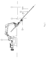
- Figs. 1-8 show the consecutive steps of the method according to the invention.
- Fig. 1 shows a sheet pile wall 1, which is placed in the ground 2.
- various accessories are put in place.
- a digging machine 3 Opposite the sheet pile wall 1, there is a digging machine 3 which has been converted so as to be able to insert screw anchors 5 into the ground.
- an insertion device 4 is located on an arm 3a of the digging machine 3.
- a part of a screw anchor can be arranged on the insertion device 4 and subsequently inserted into the ground 2 by means of a rotating movement.
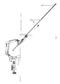
- Fig. 2 shows a second step for inserting a screw anchor 5 into the ground 2.
- the screw anchor 5 consists of multiple parts.
- the screw anchor 5 has a head part 5a which is connected to the other tube parts 5c by means of a bayonet fastening 5b.
- the tube parts 5c are connected to one another by means of screw thread connections 5d.
- the tube parts are preferably coupled to one another by means of a conical screw thread and the external surface of the tube parts is smooth at the transition.
- the screw thread connection is located inside the outside diameter of the exterior of the tube part 5c. This is advantageous when the tube parts 5c are inserted into the ground as no earth accumulates around the transitions of the tube parts, which would lead to additional resistance when the latter are inserted into the ground. Due to the fact that the screw thread is conical, the alignment of the ends of the tube parts 5c relative to one another during fastening is improved and the screw thread connection is relatively easy to release.
- Screw blade windings having an outer diameter of approximately 400 mm are provided on the head part 5a. As a result, it is possible to drill the screw anchor 5 into the ground using a rotary movement. This rotary movement is provided by the insertion device 4 which is attached to the digging machine 3. Due to the large diameter of the screw blade windings, the screw anchor offers a large resistance when a tensile force is exerted on the tension anchor.
- Fig. 3 shows a third step of the method according to the invention, in which the screw anchor 5 is inserted into the ground at the desired depth.
- the desired depth is determined by the composition of the ground.
- the screw anchor 5 is usually drilled into the ground 2 to such an extent that the head part 5a, which forms the distal end of the screw anchor, is located in a stable layer of sand.
- several tube parts 5c are coupled to the screw anchor 5.
- grout is introduced as hardening substance.
- grout is introduced as hardening substance through the tube parts 5c to the head part 5a during the insertion of the screw anchor.
- Fig. 3 shows an enlarged detail III of the head part 5a.
- Outlet openings 5d are provided in the head part 5a in such a manner that the grout there flows out of the outlet openings at a pressure of, for example, 20 bar, and spreads around the screw anchor 5.
- a grout body 6 will have formed in the ground.
- a few measures are taken before the grout has hardened. These measures are shown in the following figures.
- Fig. 4 shows a fourth step of the method according to the invention.
- tensioning bodies are conducted through the tube parts 5c towards the head part 5a in the screw anchor 5.
- steel cables are used as tensioning bodies, as these advantageously have a rough outer surface.
- the rough outer surface results from the fact that the steel cable comprises a bundle of wound steel wires. This rough outer surface provides a good contact surface with the grout.
- a further advantage of a steel cable is that it is relatively flexible compared to a tubular tensioning body and can thus be tensioned and secured in a simple manner.
- it is also possible to use different materials instead of a steel cable as tensioning body such as reinforcing iron, guy ropes, ropes, chains, etc.
- one or more steel cables or rods may be introduced.
- Fig. 5 shows a fifth step of the method according to the invention, in which, before the grout hardens to form a grout body 6, the bayonet fastening 5b between the head part 5a and the other tube parts 5c is released.
- the bayonet fastening 5b can be released in a simple manner by rotating in a direction opposite to the direction of rotation required to drill the screw anchor 5 into the ground 2.
- the tube parts 5c can be withdrawn from the ground 2.
- the tube parts 5c can be re-used.
- Fig. 6 shows the sixth step of the method according to the invention, in which the tube parts 5c are withdrawn.
- the hollow space resulting from the removal of the tube parts 5c is filled by simultaneously injecting grout while the tube parts 5c are being withdrawn. This grout is injected at a pressure lower than, for example, 5 bar.
- Fig. 7 shows a seventh step of the method according to the invention, in which the grout, after some time, has hardened to form the grout body 6.
- an anchor block 9 is provided at the location of the sheet pile wall 1.
- the tensioning bodies 7 which have in the meantime formed a solid connection with the head part 5a as a result of the hardening of the grout are attached to the anchor block 9.
- Fig. 8 shows an eighth step of the method according to the invention, in which the strands 7 which are attached to the anchor block 9 are tensioned using auxiliary equipment 8.
- auxiliary equipment 8 By tensioning the tensioning bodies 7, a tensile force will be exerted on the sheet pile wall 1, thus preventing the sheet pile wall 1 from collapsing under, for example, the pressure from the ground 2.
- Fig. 9 shows cross sections of tension anchors of different diameters. Cross sections of tensioning bodies 7 are shown inside the internal diameter of the tension anchor. Tension anchors having a small internal diameter of 40 millimetres provide space for three tensioning bodies 7 with a diameter of 15 millimetres. As Fig. 9 shows, with larger tension anchors having a diameter of 110 millimetres as many as 25 tensioning bodies with a diameter of 15 millimetres can be introduced.
- the release of the head part may also be effected by a controlled explosion, breaking, loosening a screw thread connection, etc.
- the head part and the tube part of the tension anchor may also be pushed over one another telescopically or only rest against one another, with the tube part pushing the head part and the head part remaining behind upon withdrawal of the tube part.
- a method for inserting a tension anchor into the ground for anchoring building structures which is efficient so that a cost-saving can be achieved with respect to material and labour.
Landscapes
- Engineering & Computer Science (AREA)
- Structural Engineering (AREA)
- Life Sciences & Earth Sciences (AREA)
- General Life Sciences & Earth Sciences (AREA)
- Mining & Mineral Resources (AREA)
- Paleontology (AREA)
- Civil Engineering (AREA)
- General Engineering & Computer Science (AREA)
- Piles And Underground Anchors (AREA)
Applications Claiming Priority (1)
| Application Number | Priority Date | Filing Date | Title |
|---|---|---|---|
| NL1030624A NL1030624C2 (nl) | 2005-12-08 | 2005-12-08 | Werkwijze voor het inbrengen van een trekanker in de grond. |
Publications (1)
| Publication Number | Publication Date |
|---|---|
| EP1795656A2 true EP1795656A2 (de) | 2007-06-13 |
Family
ID=36743387
Family Applications (1)
| Application Number | Title | Priority Date | Filing Date |
|---|---|---|---|
| EP20060077200 Withdrawn EP1795656A2 (de) | 2005-12-08 | 2006-12-08 | Verfahren zum Einfügen eines Zugankers in den Boden |
Country Status (2)
| Country | Link |
|---|---|
| EP (1) | EP1795656A2 (de) |
| NL (1) | NL1030624C2 (de) |
Cited By (1)
| Publication number | Priority date | Publication date | Assignee | Title |
|---|---|---|---|---|
| EP3546654A1 (de) | 2014-12-30 | 2019-10-02 | High Five Solutions B.v. | Verfahren zum entfernen eines ankers oder gründungspfahls aus dem boden |
Family Cites Families (4)
| Publication number | Priority date | Publication date | Assignee | Title |
|---|---|---|---|---|
| FR1243359A (fr) * | 1958-12-31 | 1960-10-07 | Procédé pour la fixation dans le sol d'un dispositif d'ancrage travaillant à la traction | |
| US3371494A (en) * | 1966-02-04 | 1968-03-05 | Atlas Copco Ab | Method and means of anchoring an object in the ground |
| DE2800370C2 (de) * | 1978-01-05 | 1988-11-10 | Philipp Holzmann Ag, 6000 Frankfurt | Verfahren und Vorrichtung zum Einbauen eines Verpreßankers in eine Bodenformation gegen drückendes Wasser |
| ATE434088T1 (de) * | 1999-09-23 | 2009-07-15 | Forasol S A | Bohr- und ankervorrichtung und verfahren zum setzen von verpressankern |
-
2005
- 2005-12-08 NL NL1030624A patent/NL1030624C2/nl not_active IP Right Cessation
-
2006
- 2006-12-08 EP EP20060077200 patent/EP1795656A2/de not_active Withdrawn
Cited By (2)
| Publication number | Priority date | Publication date | Assignee | Title |
|---|---|---|---|---|
| EP3546654A1 (de) | 2014-12-30 | 2019-10-02 | High Five Solutions B.v. | Verfahren zum entfernen eines ankers oder gründungspfahls aus dem boden |
| EP3240931B1 (de) | 2014-12-30 | 2020-02-19 | High Five Solutions B.v. | Verfahren zum herstellen einer ankerung im boden |
Also Published As
| Publication number | Publication date |
|---|---|
| NL1030624C2 (nl) | 2007-06-12 |
Similar Documents
| Publication | Publication Date | Title |
|---|---|---|
| KR100958696B1 (ko) | 쐐기력을 이용한 프리텐션 네일공법 | |
| KR100861938B1 (ko) | 연약지반 보강 앵커 및 상기 앵커를 이용한 시공방법 | |
| WO2017034152A1 (ko) | 개선된 구조의 영구앵커 공법용 선단정착앵커 | |
| KR101236765B1 (ko) | 말뚝이나 인장부재의 지지력 확대를 위해 천공확장부에 접합채움재를 타설하는 방법 및 그 장치 | |
| JP2010121288A (ja) | 杭の回転圧入方法と同方法に用いる回転圧入杭 | |
| KR101178043B1 (ko) | 케이블 볼트 및 케이블 볼트를 이용한 시공방법 | |
| KR100797800B1 (ko) | 영구앵커의 선단정착구 | |
| CN1934319A (zh) | 用于在土壤或岩石材料中钻孔及用于形成锚固的方法和装置 | |
| EP1795656A2 (de) | Verfahren zum Einfügen eines Zugankers in den Boden | |
| JP7048936B2 (ja) | 自穿孔ロックボルト及びそれを用いた地山の補強工法 | |
| JP2001090067A (ja) | ロックボルトおよびロックボルト施工方法 | |
| JP4745926B2 (ja) | 部分二重管方式のロックボルト構築方法 | |
| US7320371B2 (en) | Method and device for producing pretensioned anchorings | |
| JP5504463B2 (ja) | コンクリート躯体の補強方法 | |
| JP2004137760A (ja) | 削孔ロッドを用いた二重管掘りロックボルトの構築方法 | |
| KR20090007218U (ko) | 인장부재 제거형 그라운드 앵커 | |
| JPH11510230A (ja) | 地中にグランドアンカーを入れる方法およびそれに用いられるアンカー | |
| JPH04194227A (ja) | 管状補強材による補強土工法 | |
| JP3103038B2 (ja) | 拡底アンカー工法 | |
| JP5499335B2 (ja) | 鋼管杭およびその鋼管杭を用いた支持構造と施工方法 | |
| JP2004270228A (ja) | グラウンドアンカーの施工方法 | |
| JP4853132B2 (ja) | 基礎杭の施工方法 | |
| JPS6046210B2 (ja) | 水平力強化杭工法及びその装置 | |
| KR100717252B1 (ko) | 어스앵커의 시공방법 및 장치 | |
| JPH07286327A (ja) | グラウンドアンカーの施工方法 |
Legal Events
| Date | Code | Title | Description |
|---|---|---|---|
| PUAI | Public reference made under article 153(3) epc to a published international application that has entered the european phase |
Free format text: ORIGINAL CODE: 0009012 |
|
| AK | Designated contracting states |
Kind code of ref document: A2 Designated state(s): AT BE BG CH CY CZ DE DK EE ES FI FR GB GR HU IE IS IT LI LT LU LV MC NL PL PT RO SE SI SK TR |
|
| AX | Request for extension of the european patent |
Extension state: AL BA HR MK YU |
|
| STAA | Information on the status of an ep patent application or granted ep patent |
Free format text: STATUS: THE APPLICATION IS DEEMED TO BE WITHDRAWN |
|
| 18D | Application deemed to be withdrawn |
Effective date: 20130702 |