EP0757215A2 - Absorptionskältegerät - Google Patents
Absorptionskältegerät Download PDFInfo
- Publication number
- EP0757215A2 EP0757215A2 EP96112382A EP96112382A EP0757215A2 EP 0757215 A2 EP0757215 A2 EP 0757215A2 EP 96112382 A EP96112382 A EP 96112382A EP 96112382 A EP96112382 A EP 96112382A EP 0757215 A2 EP0757215 A2 EP 0757215A2
- Authority
- EP
- European Patent Office
- Prior art keywords
- cooling
- heat
- absorption
- function portion
- operation fluid
- Prior art date
- Legal status (The legal status is an assumption and is not a legal conclusion. Google has not performed a legal analysis and makes no representation as to the accuracy of the status listed.)
- Granted
Links
Images



Classifications
-
- F—MECHANICAL ENGINEERING; LIGHTING; HEATING; WEAPONS; BLASTING
- F25—REFRIGERATION OR COOLING; COMBINED HEATING AND REFRIGERATION SYSTEMS; HEAT PUMP SYSTEMS; MANUFACTURE OR STORAGE OF ICE; LIQUEFACTION SOLIDIFICATION OF GASES
- F25B—REFRIGERATION MACHINES, PLANTS OR SYSTEMS; COMBINED HEATING AND REFRIGERATION SYSTEMS; HEAT PUMP SYSTEMS
- F25B37/00—Absorbers; Adsorbers
-
- F—MECHANICAL ENGINEERING; LIGHTING; HEATING; WEAPONS; BLASTING
- F25—REFRIGERATION OR COOLING; COMBINED HEATING AND REFRIGERATION SYSTEMS; HEAT PUMP SYSTEMS; MANUFACTURE OR STORAGE OF ICE; LIQUEFACTION SOLIDIFICATION OF GASES
- F25B—REFRIGERATION MACHINES, PLANTS OR SYSTEMS; COMBINED HEATING AND REFRIGERATION SYSTEMS; HEAT PUMP SYSTEMS
- F25B17/00—Sorption machines, plants or systems, operating intermittently, e.g. absorption or adsorption type
-
- F—MECHANICAL ENGINEERING; LIGHTING; HEATING; WEAPONS; BLASTING
- F25—REFRIGERATION OR COOLING; COMBINED HEATING AND REFRIGERATION SYSTEMS; HEAT PUMP SYSTEMS; MANUFACTURE OR STORAGE OF ICE; LIQUEFACTION SOLIDIFICATION OF GASES
- F25B—REFRIGERATION MACHINES, PLANTS OR SYSTEMS; COMBINED HEATING AND REFRIGERATION SYSTEMS; HEAT PUMP SYSTEMS
- F25B15/00—Sorption machines, plants or systems, operating continuously, e.g. absorption type
- F25B15/02—Sorption machines, plants or systems, operating continuously, e.g. absorption type without inert gas
-
- F—MECHANICAL ENGINEERING; LIGHTING; HEATING; WEAPONS; BLASTING
- F25—REFRIGERATION OR COOLING; COMBINED HEATING AND REFRIGERATION SYSTEMS; HEAT PUMP SYSTEMS; MANUFACTURE OR STORAGE OF ICE; LIQUEFACTION SOLIDIFICATION OF GASES
- F25B—REFRIGERATION MACHINES, PLANTS OR SYSTEMS; COMBINED HEATING AND REFRIGERATION SYSTEMS; HEAT PUMP SYSTEMS
- F25B29/00—Combined heating and refrigeration systems, e.g. operating alternately or simultaneously
- F25B29/006—Combined heating and refrigeration systems, e.g. operating alternately or simultaneously of the sorption type system
-
- F—MECHANICAL ENGINEERING; LIGHTING; HEATING; WEAPONS; BLASTING
- F25—REFRIGERATION OR COOLING; COMBINED HEATING AND REFRIGERATION SYSTEMS; HEAT PUMP SYSTEMS; MANUFACTURE OR STORAGE OF ICE; LIQUEFACTION SOLIDIFICATION OF GASES
- F25B—REFRIGERATION MACHINES, PLANTS OR SYSTEMS; COMBINED HEATING AND REFRIGERATION SYSTEMS; HEAT PUMP SYSTEMS
- F25B2315/00—Sorption refrigeration cycles or details thereof
- F25B2315/002—Generator absorber heat exchanger [GAX]
-
- F—MECHANICAL ENGINEERING; LIGHTING; HEATING; WEAPONS; BLASTING
- F25—REFRIGERATION OR COOLING; COMBINED HEATING AND REFRIGERATION SYSTEMS; HEAT PUMP SYSTEMS; MANUFACTURE OR STORAGE OF ICE; LIQUEFACTION SOLIDIFICATION OF GASES
- F25B—REFRIGERATION MACHINES, PLANTS OR SYSTEMS; COMBINED HEATING AND REFRIGERATION SYSTEMS; HEAT PUMP SYSTEMS
- F25B2315/00—Sorption refrigeration cycles or details thereof
- F25B2315/006—Reversible sorption cycles
-
- Y—GENERAL TAGGING OF NEW TECHNOLOGICAL DEVELOPMENTS; GENERAL TAGGING OF CROSS-SECTIONAL TECHNOLOGIES SPANNING OVER SEVERAL SECTIONS OF THE IPC; TECHNICAL SUBJECTS COVERED BY FORMER USPC CROSS-REFERENCE ART COLLECTIONS [XRACs] AND DIGESTS
- Y02—TECHNOLOGIES OR APPLICATIONS FOR MITIGATION OR ADAPTATION AGAINST CLIMATE CHANGE
- Y02A—TECHNOLOGIES FOR ADAPTATION TO CLIMATE CHANGE
- Y02A30/00—Adapting or protecting infrastructure or their operation
- Y02A30/27—Relating to heating, ventilation or air conditioning [HVAC] technologies
-
- Y—GENERAL TAGGING OF NEW TECHNOLOGICAL DEVELOPMENTS; GENERAL TAGGING OF CROSS-SECTIONAL TECHNOLOGIES SPANNING OVER SEVERAL SECTIONS OF THE IPC; TECHNICAL SUBJECTS COVERED BY FORMER USPC CROSS-REFERENCE ART COLLECTIONS [XRACs] AND DIGESTS
- Y02—TECHNOLOGIES OR APPLICATIONS FOR MITIGATION OR ADAPTATION AGAINST CLIMATE CHANGE
- Y02B—CLIMATE CHANGE MITIGATION TECHNOLOGIES RELATED TO BUILDINGS, e.g. HOUSING, HOUSE APPLIANCES OR RELATED END-USER APPLICATIONS
- Y02B30/00—Energy efficient heating, ventilation or air conditioning [HVAC]
- Y02B30/62—Absorption based systems
Definitions
- This invention relates to an absorption type refrigerating machine (to be referred to as "absorption type refrigerating apparatus" in the present invention) such as an absorption refrigerating machine or absorption water cooler/heater in which desired heat exchange operation is performed by an absorption heat pump function which uses an absorption solution mixed with a refrigerant to cool or heat a target heat operation fluid.
- absorption type refrigerating apparatus such as an absorption refrigerating machine or absorption water cooler/heater in which desired heat exchange operation is performed by an absorption heat pump function which uses an absorption solution mixed with a refrigerant to cool or heat a target heat operation fluid.
- an absorption type refrigerating apparatus which uses a fluid having a relatively low evaporation temperature such as NH 3 , i.e., ammonia, as a refrigerant and an inexpensive, harmless fluid having a relatively high evaporation temperature compared with this refrigerant, such as a water mixture, as an absorption solution has been conventionally known.
- a fluid having a relatively low evaporation temperature such as NH 3 , i.e., ammonia
- Another conventionally known absorption type refrigerating apparatus has such constitution that a function to provide a function to carry out desired heat exchange, i.e., generator-absorber heat exchanging function (generator-absorber heat exchanger), is provided between a generator for evaporating the above refrigerant by heating the above absorption solution and an absorber for causing the above refrigerant to be absorbed into the above water to enhance heat operation efficiency.
- generator-absorber heat exchanging function is called "GAX function”.
- a diluted solution 2b having a low concentration of a refrigerant accumulated in the bottom of a generator 5 as a starting point.
- the diluted solution 2b passes through a heat exchange pipe 205A, an absorption solution heat exchanger 31 and a pressure reducing unit 9 due to the difference between pressure inside the generator 5 and pressure inside the absorber 1, is sprayed through a spray pipe 201D, absorbs refrigerant vapor 7c to become a concentrated solution 2a while it is dropping along a heat exchange pipe 201X, a heat exchange pipe 201B and a cooling pipe 201A, and accumulates in the bottom of the absorber 1.
- the concentrated solution 2a circulates in the following way, applied pressure by a pump 3. It passes through the heat exchange pipe 201B, a heat exchange pipe 205D, an absorption solution heat exchanger 31 and the heat exchange pipe 201X. During this period, the concentrated solution 2a absorbs heat generated when the diluted solution 2c sprayed through the spray pipe 201D absorbs refrigerant vapor 7c and then heat of the refrigerant vapor 7a in the heat exchange pipe 205D.
- the concentrated solution 2a is preheated as it passes through the heated side of the absorption solution heat exchanger 31, heated again in the heat exchange pipe 201X by absorbing heat generated when the sprayed diluted solution 2c absorbs the refrigerant vapor 7c, sprayed from a spray pipe 205C, evaporates the refrigerant vapor 7a while it is dropping along the heat exchange pipes 205A, and accumulates in the bottom of the generator 5 as a diluted solution 2b.
- the heat exchange pipe 201B and the heat exchange pipe 201X constitute the GAX function portion which utilizes heat present on the side of the absorber 1 to aid heating required for the generation of refrigerant vapor in the generator 5.
- the refrigerant vapor 7a is circulated as follows. Since the refrigerant vapor 7a generated by heating the diluted solution 2b by a heater 6 contains a large amount of a water vapor component, it not only increases the concentration of the refrigerant contained in the refrigerant vapor 7a, i.e., the concentration of NH 3 , owing to a gas-liquid contact function, i.e., heat exchange, separation and absorption functions generated when the refrigerant vapor is contacted to the surface of the absorption solution, but also performs a rectifying function by which excess heat is absorbed by the heat exchanger 205D.
- a gas-liquid contact function i.e., heat exchange, separation and absorption functions generated when the refrigerant vapor is contacted to the surface of the absorption solution, but also performs a rectifying function by which excess heat is absorbed by the heat exchanger 205D.
- the refrigerant vapor 7a entering the condenser 11 through the pipe line 10 discharges heat by giving heat to a first heat operation fluid 35a which passes through a heated side 11A, e.g., water, condenses into a refrigerant solution 7b which then passes through a pipe line 12 and enters the pressure reducing unit 13.
- a heated side 11A e.g., water
- a refrigerant solution 7b which then passes through a pipe line 12 and enters the pressure reducing unit 13.
- Each of the pressure reducing units 9 and 13 is formed of a pressure reducing valve, e.g..
- the refrigerant solution 7b whose pressure has been reduced by the pressure reducing unit 13 enters the evaporator 14, absorbs heat from a second heat operation fluid 35b passing through the cooled side 14A of the evaporator 14, e.g., water, to evaporate and become refrigerant vapor 7c which then passes through the pipe line 15 and returns to the absorber 1.
- a second heat operation fluid 35b passing through the cooled side 14A of the evaporator 14, e.g., water
- the refrigerant solution 7b provides required heat operation to the first heat operation fluid 35a passing through the pipe lines 20, 21, 22 and 23 and the second heat operation fluid 35b passing through the pipe lines 24 and 25.
- the connection path between the outdoor heat exchanger 61 and the indoor heat exchanger 62 can be changed by a pipe line connection switch 63, a pump 64 is a pump for promoting the circulation of the first heat operation fluid 35a passing through the heated side 11A of the condenser 11, e.g., water, and a pump 65 is a pump for promoting the circulation of the second heat operation fluid 35b passing through the cooled side 14A of the evaporator 14, e.g., water.
- a heat operation fluid to be heated or cooled e.g., water for heating or cooling
- a fluid for absorbing or discharging heat e.g., water for absorbing or discharging heat by passing through a radiator with a fin
- the pipe lines 20 and 21 for supplying the first heat operation fluid 35a to the cooling pipe 201A of the absorber 1, the pipe lines 22 and 23 for supplying the first heat operation fluid 35a to the heated side 11A of the condenser 11 and the pipe lines 24 and 25 for supplying the second heat operation fluid 35b to the cooled side 14A of the evaporator 14.
- the pipe line connection switch 63 is a switch valve for switching between connection paths shown by solid lines and connection paths shown by dotted lines for eight pipe lines in the figure. Since it switches among eight pipe lines, it is also called “eight-way valve". It performs switching operation by operating a switch axis by means of an electric actuator which becomes operative in response to a control signal from a controller (to be referred to as "CPU” hereinafter) formed of a microcomputer.
- a controller to be referred to as "CPU” hereinafter
- a circulation system for cooling operation by means of heat operation fluids is constructed by forming the following paths according to switch connections for paths shown by solid lines: (1) a heat discharge path in which heat discharge operation is performed by forcedly giving outdoor air to the heat discharge side 61A of the outdoor heat exchanger 61 by means of a fan 61B while the first heat operation fluid 35a is circulated in a circulation path from the pipe line 20, cooling pipe 201A, pipe line 21, pipe line 22, heated side 11A of the condenser 11, pipe line 23, pipe line connection switch 63, outdoor heat exchanger 61, pipe line connection switch 63 and pump 64 back to the pipe line 20 and (2) a cooling heat absorption path in which indoor air cooling operation is performed by forcedly providing indoor air by means of a fan 62B for circulation to the cooled side 62A of the indoor heat exchanger 62 while the second heat operation fluid 35b is circulated in a circulation path from the pipe line 24, the cooled side 14A of the evaporator 14, pipe line 25, pipe line connection switch 63, indoor heat exchanger 62, pipe
- a circulation system for heating operation by means of heat operation fluids is constructed by forming the following paths according to switch connections for paths shown by dotted lines: (1) a heat discharge path in which indoor air is heated by forcedly providing indoor air to the heated side 62A of the indoor heat exchanger 62 while the first heat operation fluid 35a is circulated in a circulation path from the pipe line 20, cooling pipe 201A, pipe line 21, pipe line 22, heated side 11A of the condenser 11, pipe line connection switch 63, indoor heat exchanger 62, pipe line connection switch 63 and pump 64 back to the pipe line 20 and (2) a heat absorption path in which heat absorption operation is performed by forcedly providing outdoor air by means of a fan 61B to the heat absorption side 61A of the indoor heat exchanger 61 while the second heat operation fluid 35b is circulated in a circulation path from the pipe line 24, the cooled side 14A of the evaporator 14, pipe line 25, pipe line connection switch 63, indoor heat exchanger 61, pipe line connection switch 63 and pump 65 back to the pipe line 24.
- the control of the cooling or heating operation of the heat operation fluids is carried out by a control signal from each part of the CPU 70.
- This control is performed by controlling the operations of the heater 6, the pipe line connection switch 63 and the pumps 3, 64 and 65, etc. in response to control signals which are obtained by supplying to the CPU 70 detection signals obtained by detecting the operation states of required parts, e.g., temperature, and a setting signal from a setting operation unit 80 for setting operation conditions and carrying out required control processings at the CPU 70.
- defrosting operation for defrosting the outdoor heat exchanger 61 needs to be carried out, by which the outdoor heat exchanger is temporarily made in a cooling operation state. During this defrosting operation and after the completion of the defrosting operation, there occurs such inconvenience that the indoor heat exchanger 62 temporarily discharges cool air.
- JP-A Hei 6-94322 which has been applied by the Applicant of the present invention discloses such constitution (to be referred to as "third prior art” hereinafter) that opening/closing valves V1 and V2 between the flow passages of the first heat operation fluid 35a and the second heat operation fluid 35b are opened to join the first heat operation fluid 35a and the second heat operation fluid 35b, and an opening/closing valve V3 between the flow passage of the refrigerant vapor 7a from the generator 5 and the flow passage of the refrigerant vapor 7c entering the absorber 1 is opened to directly supply the high-temperature refrigerant vapor 7a into the absorber 1.
- JP-A Hei 6-323676 discloses such constitution (to be referred to as "fourth prior art" hereinafter) that the concentrated solution 2a is directly provided to the pressure reducing unit 9 from the heat exchanger 205A without providing the absorber solution heat exchanger 31 because there are no troubles such as the diluted solution 2b is not scattered at the exit of the spray pipe 201D and a temperature reduction is caused by scattering in the constitution of the above second prior art in which heat exchange operation can be sufficiently performed by the heat exchanger 205.
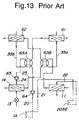
- JP-A Hei 5-272831 discloses such constitution (to be referred to as "fifth prior art" hereinafter) that the pipe line connection switch 63 in the constitution of the second prior art as described above is divided into the pipe line connection switch 63A and the pipe line connection switch 63B separately, each formed of a four-way valve as shown in Fig. 13.
- FIG. 13 portions represented by the same reference symbols as those in Fig. 12 have the same functions as portions having the same reference symbols in Fig. 12.
- the pipe line connection switch 63A and the pipe line connection switch 63B can be switched simultaneously. Connection paths shown by solid lines and connection paths shown by dotted lines in the pipe line connection switch 63 of Fig. 12 correspond to connection paths shown by solid lines and connection paths shown by dotted lines in the pipe line connection switch 63A and the pipe line connection switch 63B, respectively. Since the pipe line connection switch 63A and the pipe line connection switch 63B are a switching valve for switching among four pipe lines, they are called "four-way valve".
- the cooling path of the first heat operation fluid 35a with respect to the cooling pipe 201A of the absorber 1 and the condenser 11, i.e., cooling water, is formed as a serial path in which the cooling pipe 201A of the absorber 1 comes before the condenser 11, when the cooling amount is large in the cooling stage of the cooling pipe 201A of the absorber 1, the cooling amount becomes small in the cooling stage of the condenser 11.
- the cooling path of the first heat operation fluid 35a with respect to the cooling pipe 201A of the absorber 1 and the condenser 11 i.e., cooling water
- the flow passage of the first heat operation fluid 35a i.e., cooling water
- the flow passage of the second heat operation fluid i.e., cold/hot water used for air-conditioning are switched by an eight-way valve or two two-way valves. Therefore, since heat exchange is performed between the heat operation fluids through the valve chests or valve bodies of these switching valves, a heat loss is produced and there is such inconvenience that the performance coefficient of the entire system cannot be improved sufficiently.
- the pipe line of the first heat operation fluid 35a i.e., cooling water
- an eight-way valve or four-way valve for switching the flow passage of cooling water becomes large in size, the apparatus cannot be made small in size.
- the valve switching unit of the eight-way valve or four-way valve is generally driven by a motor, quick switching operation cannot be performed due to movement inertia and switching operation is slow during defrosting operation. Therefore, there is such inconvenience that an unpleasant feeling is given to a human body.
- the present invention provide the apparatus having constitutions as follows:
- Figs. 1 to 11 show the embodiments of the present invention and Figs. 12 and 13 show the prior arts.
- FIGs. 1 to 11 With reference to Figs. 1 to 11, the preferred embodiments of the present invention will be described.
- portions denoted at the same reference symbols as those in Figs. 12 and 13 have the same functions as portions having the same reference symbols in Figs. 12 and 13.
- portions denoted at the same reference symbols have the same functions as portions having the same reference symbols in any one of Figs. 1 to 11.
- the outdoor heat exchanger 61, indoor heat exchanger 62, pipe line connection switch 63, CPU 70 and setting operation unit 80 are not shown and each fluid flows in a direction shown by arrows.
- the generator 5 firstly, most of the inner portion is partitioned by spiral shelves 5A arranged spirally on the inner wall of the outer shell and the heat exchanger 205A is coiled and arranged between adjacent spiral shelves 5A so that heat exchange between the refrigerant vapor 7a and the diluted solution 2b in the heat exchanger 205A can be improved. Secondly, a rectifying portion 206 rectifies making use of a passage formed by the spiral shelves 5A. Thirdly, at the uppermost portion of the generator 5, a reflux portion 205F is formed of a pipe line which is coiled such that the heat exchange pipe 205F1 can follow the spiral shelves 5A.
- the heat exchange pipe 205F1 of the reflux portion 205F performs fractional distillation operation for condensing part of the refrigerant vapor 7a by means of a relatively low-temperature concentrated solution 2a by causing heat exchange to be performed between the concentrated solution 2a from the bottom of the absorber 1 passing through the inside of the heat exchanger 205F1 and the refrigerant vapor 7a, so as to rectify the refrigerant vapor 7a, i.e., increase the concentration of the refrigerant contained in the refrigerant vapor 7a.
- a safety valve 205G is provided to maintain safety by discharging the refrigerant vapor to the outside when the pressure of the refrigerant vapor 7a inside the generator 5 rises to a level beyond safety.
- a storage tank 213 for storing the condensed refrigerant 7b and a heat exchanger 214 for precooling are provided along the pipe line 12 so that the refrigerant solution 7b is caused to flow into the evaporator 14 after it is a little cooled.
- an expansion valve 13A is provided between the heat exchanger 214 for precooling and the evaporator 14 in place of the pressure reducing unit 13.
- safety valves 231A and 232A for maintaining safety by discharging abnormal vapor or abnormal pressure when they occur and opening/closing valves 231B and 232B for supplying heat operation fluids 35a and 35b are provided in the flow passage of the first heat operation fluid 35a and the flow passage of the second heat operation fluid 35b, respectively.
- the concentrated solution 2a supplied from the pump 3 is circulated by a route from the upper end side of the heat exchange pipe 205F1 of the reflux portion 205F, the lower end side of the heat exchange pipe 205F1, the lower end side of the heat exchange pipe 201B, the upper end side of the heat exchange pipe 201B, the lower end side of the heat exchange pipe 201X, the upper end side of the heat exchange pipe 201X and the heated side 31A of the absorption solution heat exchanger 31 to the spray pipe 205C.
- a cooling circuit for reflux use can be omitted by the above circulation of the concentrated solution 2a and the arrangement of the pipe line 203 on the way to the heat exchange pipe 201B and the heat exchange pipe 201X is facilitates.
- an additional pipe line for returning the concentrated solution 2a to a lower portion of the heat exchange pipe 205D must be provided along the pipe line between the heat exchange pipe 205D and the absorption solution heat exchanger 31 so as to increase the GAX effect.
- the concentrated solution 2a which has passed through the pipe line 203 branched off from the connection section between the pipe line 17 on the upper end side of the heat exchange pipe 201B and the pipe line 8 on the lower end side of the heat exchange pipe 201X is sprayed from a spray pipe 205H arranged right above the rectifying portion 206.
- the concentrated solution 2a having a temperature lower than saturation temperature is provided to the rectifying portion 206 by this spraying to absorb heat generated in the rectifying portion 206. Therefore, this spraying is preferably carried out at a location slightly below the intermediate position of the rectifying portion 206.
- the pipe line 20 is divided into pipe lines 20A and 20B to form two routes: one from the pipe line 20B, the cooling side of the condenser 11 and pipe line 20C to cooling pipe 201A of the absorber 1; and the other from pipe line 20A, the cooling side of the absorption/heat exchanger 234 and pipe line 20D to the cooling pipe 201A of the absorber 1.
- parallel and serial portions are provided in the cooling flow passage of the first heat operation fluid 35a.
- the absorber 1 firstly, the diluted solution 2c1 whose temperature is raised by causing the refrigerant vapor 7c to be absorbed by alternate shelves 201E provided right below the spray pipe 201D until a state close to phase equilibrium is reached when the temperature of the diluted solution 2c is too low, i.e., overcooling, or the diluted solution 2c1 which is cooled when the temperature of the diluted solution 2c is too high, i.e., overheating, is received and stored in a pan 201J temporarily and then dropped along the heat exchange pipe 201X and the heat exchange pipe 201B from dropping holes formed in the pan 201J.
- the absorption solution 2c2 which has achieved an intermediate concentration while it is dropped along the heat exchange pipe 201X and the heat exchange pipe 201B is temporarily received and stored in a pan 201F provided at a portion half the height of the absorber 1 and then dropped along the cooling pipe 201A from dropping holes formed in the pan 201F and the refrigerant vapor 7c inside the absorber 1 passes through ventilation holes 1B and 1D provided at the outer peripheries of the pans 201F and 201J to flow into chambers partitioned by the pans 201F and 201J, respectively.
- a cooling function portion for cooling the absorption function portion of the absorber 1 by means of the first heat operation fluid 35a, i.e., cooling water, is composed of a cooling function portion formed of the cooling pipe 201A provided inside the absorber 1 and a cooling function portion formed of the absorption/heat exchanger 234 which also serves as an absorption function and is arranged outside the absorber 1.
- a mixture solution 2d of the concentrated solution 2a and the refrigerant vapor 7c is circulated in the cooled side 234A of the absorption/heat exchanger 234 from the bottom of the absorber 1 through a pipe line 4 and the first heat operation fluid 35a is circulated in the cooling side 234B to carry out an absorption function by the concentrated solution 2a and the refrigerant vapor 7c contained in the mixture solution 2d in the cooled side 234A, and then the remaining refrigerant vapor 7c is discharged or absorbed in the storage portion 235 to cause only the concentrated solution 2a to flow into the pump 3 if possible.
- the absorption/heat exchanger 234 may be constituted as either one of the following heat exchangers to construct as a small apparatus as possible: (1) a double tube type heat exchanger in which a pipe having a large diameter and a pipe having a small diameter are arranged coaxially, the flow passage of one pipe is made a cooling side, and that of the other pipe is made a cooled side, (2) a shell tube type heat exchanger in which a plurality of small pipes are arranged in parallel in a large can body, flow passages in the plurality of small pipes are made cooling sides or cooled sides and a flow passage formed between the large can body and the plurality of small pipes is made a cooled side or a cooling side, (3) a shell-coil can heat exchanger in which a small coiled pipe is arranged inside a large can body and a flow passage in the coiled pipe is made a cooling side or cooled side and a flow passage between the can body and the coiled pipe is made a cooled side or cooling side,
- the cooing side 234B of the absorption/heat exchanger 234 and the cooling pipe 201A of the absorber 1 are connected in series.
- the cooling side 234B of the absorption/heat exchanger 234 and the cooling pipe 201A of the absorber 1 may be connected in parallel by changing the flow passages of the pipes 20A, 20C and 20D as shown in Fig. 5 according to the distribution of the cooling amount to the cooling side of the condenser 11 and the cooling pipe 201A.
- the absorption/heat exchanger 234 only one cooling function portion arranged outside the absorber 1, i.e., the absorption/heat exchanger 234 is arranged.
- a plurality of absorption/heat exchangers similar to the absorption/heat exchanger 234 may be arranged to constitute the cooling function portion.
- Another cooling pipe 201G is provided at a location where the cooling pipe 201A is arranged inside the absorber 1, the lower end side of the cooling pipe 201G is connected to the pipe line 20C, the upper side of the cooling pipe 201G is connected to the pipe line 21, and the lower end side of the cooling pipe 201A is connected only to the pipe line 20D so that the first heat operation fluid 35a flows parallel in the cooling pipe 201A and the cooling pipe 201G.
- the cooling pipe 201A and the cooling pipe 201G are constituted such that a coiled pipe line having a small coiling diameter is placed inside the coil of a coiled pipe line having a large coiling diameter to form two cooling pipes without increasing the outer diameter and height thereof, one of the thus formed two coiled pipe lines is made the cooling pipe 201A and the other the cooling pipe 201G. In this way, the two cooing pipes 201A and 201G are provided without increasing the size of the absorber 1.
- the flow passage of the first operation fluid 35a i.e., cooling water, formed by the cooling pipe 201A, the cooling pipe 201G and the cooling side 234B of the absorption/heat exchanger 234 may be constituted such that a flow passage formed by the pipe lines 20A, 20C and 20D is changed as shown in Fig. 6 according to the distribution of the cooling amount to the cooling side of the condenser 11 and the cooling pipe 201A like a modification of the above Embodiment 1 shown in Fig. 5 and a flow control valve 236 is directly provided along a flow passage toward the pipe line 21 from the pipe line 20D to arrange the cooling side 234B of the absorption/heat exchanger 234 and the cooling pipe 201A of the absorber 1 in parallel.
- a flow control valve 236 is directly provided along a flow passage toward the pipe line 21 from the pipe line 20D to arrange the cooling side 234B of the absorption/heat exchanger 234 and the cooling pipe 201A of the absorber 1 in parallel.
- the cooling function portion provided inside the absorber 1 is composed of two cooling pipes 201A and 201G.
- the number of cooling pipes for forming the cooling function portion may be three which are arranged likewise.
- absorption/heat exchanger 234 a plurality of absorption/heat exchangers similar to the absorption/heat exchanger 234 may be provided to constitute the cooling function portion, or the absorption/heat exchanger 234 may be removed.
- Another cooling pipe 201H is provided outside the location of the cooling pipe 201A inside the absorber 1, the lower end of the cooling pipe 201H is connected to the pipe line 20C, the upper end side of the cooling pipe 201H is connected to the pipe line 21, and the lower end side of the cooling pipe 201A is connected only to the cooling pipe 20D so that the first heat operation fluid 35a flows parallel in the cooling pipe 201A and the cooling pipe 201H.
- the cooling pipe 201H perform cooling operation efficiently, as shown in Fig. 4(a), the cooling pipe 201H is coiled around the outer shell 1A of the absorber 1 in such a manner that it is closely adhered to the outer periphery of the outer shell 1A, and the cooling pipe 201H made of a copper material and the outer shell 1A made of a stainless steel material are soldered together with silver or copper 300 so that the outer shell 1A is integrated with the cooling pipe 201H to achieve good heat conduction, as shown in Fig.4(b).
- the inner wall of the outer shell 1A is threaded or multi-grooved to form a continuous irregular surface 1C so as to increase the heat conduction area.
- the flow passage of the first operation fluid 35a i.e., cooling water, formed by the cooling pipe 201A, the cooling pipe 201H and the cooling side 234B of the absorption/heat exchanger 234 may be constituted such that a flow passage formed by the pipe lines 20A, 20C and 20D is changed as shown in Fig. 7 according to the distribution of the cooling amount to the cooling side 234B of the condenser 11 and the cooling pipe 201A like a modification of the above Embodiment 2 shown in Fig. 6 and a flow control valve 236 is directly provided along a flow passage toward the pipe line 21 from the pipe line 20D to arrange the cooling side 234B of the absorption/heat exchanger 234 and the cooling pipe 201A of the absorber 1 in parallel.
- a flow control valve 236 is directly provided along a flow passage toward the pipe line 21 from the pipe line 20D to arrange the cooling side 234B of the absorption/heat exchanger 234 and the cooling pipe 201A of the absorber 1 in parallel.
- the cooling function portion provided inside the absorber 1 is composed of only two cooling pipes 201A and 201G.
- the number of cooling pipes for forming the cooling function portion may be three which are arranged likewise.
- absorption/heat exchanger 234 a plurality of absorption/heat exchangers similar to the absorption/heat exchanger 234 may be provided to constitute the cooling function portion, or the absorption/heat exchanger 234 may be removed.
- each pipe line shown by an arrow is for cooling operation, i.e., a route taken by each fluid for cooling operation and a flow direction shown by an arrow is for heating operation, i.e., a route taken by each fluid for heating operation.
- Paths shown by solid lines formed by pipe line connections by means of the pipe line connection switch 63C is for cooling operation and paths shown by dotted lines formed by pipe line connections is for heating operation.
- Fig. 9 With reference to Fig. 9, Embodiment 4 of the present invention will be described.
- the differences between the constitution of Fig. 9 and the constitution of Fig. 12 are as follows.
- the generator 5 firstly, most of the inner portion is partitioned by spiral shelves 5A arranged spirally on the inner wall of the outer shell, the heat exchanger 205A is coiled and arranged between adjacent spiral shelves 5A, and a rising portion 205A1 is provided on the lower end side so that heat exchange between the refrigerant vapor 7a and the diluted solution 2b in the heat exchanger 205A can be improved.
- the rectifying portion 206 rectifies making use of a passage formed by the spiral shelves 5A and at the uppermost portion of the generator 5, a reflux portion 205F is formed of a pipe line which is coiled such that the heat exchange pipe 205F1 can follow the spiral shelves 5A.
- a pipe line 10A equipped with an opening/closing valve V5 is provided to give a relatively high-temperature portion of the refrigerant vapor 7a in the generator 5 directly to the heating side of a heat exchanger 111 for condensation/evaporation to be described hereinafter.
- the pipe line connection switch 63C is formed of a pipe line connection switch for switching and connecting four pipe lines, e.g., a four-way valve.
- the heat exchanger 111 for condensation/evaporation is caused to serve as a condenser during cooling operation and as an evaporator during heating operation by reversing the route of the refrigerant circulation system by means of the pipe line connection switch 63C.
- the opening/closing valve V4 can be used to switch between the flow passage of the first heat operation fluid 35a and the flow passage of the second heat operation fluid 35b without using a multi-flow passage switch such as a four-way valve.
- a heat exchanger 101 for cooling air equipped with a fan 101B for heat exchange between the refrigerant and the outside air, a double-tubular heat exchanger 215 for preheating the refrigerant vapor 7c injected into the absorber 1 by means of the refrigerant solution on the high-temperature side of the circulation path during cooling operation, and pressure reducing units 221 and 216 and check valves 212 and 218 for returning the circulation path of the refrigerant in the preheating heat exchanger to a normal path after the reversal of the route of the refrigerant circulation system by the pipe line connection switch 63C in order to increase heat operation efficiency.
- the spray pipe 201D is formed of a spray unit formed by arranging small tubes for dropping around a plate-like member arranged at an upper part of the absorber 1, and a spray unit 201K having a similar structure is provided between the heat exchange pipe 201X and the heat exchange pipe 201B so that the diluted solution which has been sprayed from the spray unit 201D and has absorbed the refrigerant vapor 7c while it is dropping along the heat exchange pipe 201X is temporarily received and stored in the spray unit 201K as an intermediate solution 2c3, and then is caused to flow down along the heat exchange pipe 201B and the cooling pipe 201A form the spray unit 201K to increase absorption efficiency.
- the refrigerant vapor 7c is caused to flow through the through holes 201D1 and 201K1 formed around the outer periphery of the spray units 201D and 201K.
- the refrigerant vapor 7c which has been introduced into the absorber 1 from the pipe line 15 is guided from the center of the spray unit 201K to the center portions of the coiled heat exchange pipe 201B and cooling pipe 201A to increase absorption efficiency.
- convection and diffusion in the absorber 1 are suppressed by dividing the absorber 1 into upper and lower chambers by means of the spray unit 201K, whereby the amount of contact between the refrigerant vapor and the diluted solution can be increased and equilibrium can be brought to perfection.
- a heat exchanger 102 for cooling air equipped with a fan 102B for heat exchange between the concentrated solution 2a accumulated in the bottom of the absorber 1 and the outside air is provided to cause the refrigerant vapor 7c contained in a mixture fluid containing the concentrated solution 2a and the refrigerant vapor 7c which is flown in together with the concentrated solution 2a to be absorbed into the concentrated solution 2a and circulate in order to prepare an absorption solution having a high concentration.
- the concentrated solution 2a is prevented from being cooled excessively by stopping or reducing a heat exchange function by stopping or slowing down the fan 102B.
- a heat loss caused by the heat discharge of heat exchanger 102 for cooling air is reduced and heat collection by heating the refrigerant vapor 7c is promoted so as to enhance heat exchange efficiency.
- the opening/closing valve V5 is opened to give the high-temperature refrigerant vapor 7c directly to the heat exchanger 111 for condensation/evaporation so that a delay in starting heating operation at the beginning of the start of heating operation including return to heating operation from defrosting operation can be eliminated.
- the heat exchange pipe 201B and the heat exchange pipe 201X are connected in series, the absorption solution having a low concentration at a temperature close to saturation temperature is provided to an upper portion of the rectifying portion 206 from the pipe line 203 branched off at the connection point between these heat exchange pipes, and the absorption solution which is a mixture fluid containing the refrigerant vapor and the concentrated solution and having a relatively high temperature is provided to a lower portion of the rectifying portion 206 from the pipe line 202 on the upper end side of the heat exchange pipe 201X.
- the GAX function can be improved.
- a heat transmission loss caused by heat exchange operation between the first heat operation fluid 35a and the second heat operation fluid 35b can be eliminated with simple constitution that, in the paths of the circulation systems for the first heat operation fluid 35a, i.e., cooling water, and the second heat operation fluid 35b, i.e., cool/hot water, the pipe lines 20 and 21 of the first heat operation fluid 35a and the pipe lines 24 and 25 of the second heat operation fluid 35b are connected in parallel, and the opening/closing valve V4 is provided in the pipe line 25 of the first heat operation fluid 35a so that it is opened during heating operation to join the first heat operation fluid 35a and the second heat operation fluid 35b and circulate the joined fluids and closed during cooling operation to intercept the joining of the first heat operation fluid 35a and the second heat operation fluid 35b.
- the opening/closing valve V4 is provided in the pipe line 25 of the first heat operation fluid 35a so that it is opened during heating operation to join the first heat operation fluid 35a and the second heat operation fluid 35b and circulate the joined fluids and
- eighth constitution comprising:
- ninth constitution comprising:
- the heat exchanger 102 for cooling air of Fig. 9 is formed of a so-called fin radiator. That is, as shown in Fig. 10, it is constituted such that pipe lines 4 and 41 which penetrate in a zigzag manner one side surface of a fin 102a which is formed by stacking up a large number of aluminum thin plates arranged with a small space therebetween are provided between one side surface and the opposite side surface of the fin 102a and air blown by the fan 102B is let passing through the narrow spaces of the fin 102a.
- the heat exchanger 101 for cooling air is constituted likewise that pipe lines 38 and 39 which penetrate in a zigzag manner a fin 101a are provided and air blown by the fan 101B is let passing through the narrow spaces of the fin 101a.
- part of the pipe line 39 which must be caused to penetrate the fin 101a of the heat exchanger 101 for cooling air is caused to penetrate a high-temperature portion of the fin 102a of the heat exchanger 102 for cooling air so that an unevaporated refrigerant contained in the refrigerant vapor passing through the pipe lines 38 and 39 can be heated and evaporated.
- heat efficiency can be enhanced.
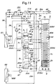
- Fig. 11 the differences from the constitution of Fig. 9 are as follows. Firstly, the air-cooled heat exchanger 102 for cooling the absorption solution, i.e., the concentrated solution 2a is removed and instead, an air-cooled heat exchanger 66 equipped with a fan 66B is arranged only for discharging heat from the first heat operation fluid 35a, i.e., cooling water.
- the first heat operation fluid 35a i.e., cooling water.
- the pipe lines 20A, 21A, 45 and 45 branching off from the pipe line 20 and the pipe line 21 are provided, a flow passage connection switch 47 formed of a three-way valves or a combination of opening/closing valves is arranged at the diverging point of the pipe lines 21, 21A and 46 in place of the opening/closing valve V4, and a check valve 48 and an opening/closing valve V6 are provided at the diverging point of the pipe lines 20, 20A and 45 on the side of the pipe line 20A and on the side of the pipe line 45, respectively.
- the pipe line connection switch 47 is controlled such that only the flow passage between the pipe lines 21 and 21A is opened during cooling operation and only the flow passage between the pipe lines 21 and 46 is opened during heating operation, the opening/closing valve V6 is closed during cooling operation and opened during heating operation, and the fan 61B and the pump 64 become operative during cooling operation only.
- This invention can be modified in the following manner.
- a cooling function portion for cooling the absorption heat of the absorber 1 is divided into a plurality of sub-portions in the absorber 1, such as cooling pipes 201A and 201G, or a plurality of sub-portions arranged inside and outside the absorber 1, such as the cooling pipes 201A, 201G and the absorption/heat exchanger 234, even when the flow rate of the first heat operation fluid 35a, i.e., cooling water, or the amount cooled by the first heat operation fluid 35a in each one of cooling function sub-portions is reduced, a large cooling amount can be achieved as a whole.
- the first heat operation fluid 35a i.e., cooling water
- the flow passages for cooling the condenser 11 and the absorber 1 by means of the first heat operation fluid 35a can be arranged in parallel or series to meet the cooling amount required by the condenser 11 and the cooling amount required by the absorber 1, or an arbitrary combination of these passages can be selected to achieve the optimal cooling efficiency.
- an apparatus capable of improving performance coefficient as an entire system can be provided.
- cooling pipe 201H arranged outside can be coiled around the outer shell 1A of the absorber 1 in such a manner that it is closely adhered to the outer shell 1A and the absorption/heat exchanger 234 can be formed into a suitable shape and installed in the remaining space left after the absorber 1 and the generator 5 have been installed, cooling efficiency can be increased with the size of the apparatus remaining the same as the prior art apparatus or possibly made smaller as required. As a result, a small-sized apparatus having an improved performance coefficient as an entire system can be provided.
- connection switching of the flow passage of the first heat operation fluid can be formed of a simple opening/closing valve.
- a single heat exchanger for condensation/evaporation functions as a condensation heat exchanger and an evaporation heat exchanger for giving a heat source to the second operation fluid by reversing the circulation path of the refrigerant vapor.
- the high-temperature refrigerant vapor in the generator is forcedly provided to the heat exchange function portion through the opening/closing valve, an apparatus free from such inconvenience that an unpleasant feeling caused by a delay in start-up time of heating is given to a human body can be provided.
Landscapes
- Engineering & Computer Science (AREA)
- Physics & Mathematics (AREA)
- Mechanical Engineering (AREA)
- Thermal Sciences (AREA)
- General Engineering & Computer Science (AREA)
- Sorption Type Refrigeration Machines (AREA)
Applications Claiming Priority (6)
| Application Number | Priority Date | Filing Date | Title |
|---|---|---|---|
| JP7216755A JPH0942795A (ja) | 1995-08-01 | 1995-08-01 | 吸収式冷凍装置 |
| JP216755/95 | 1995-08-01 | ||
| JP21675595 | 1995-08-01 | ||
| JP216756/95 | 1995-08-01 | ||
| JP21675695 | 1995-08-01 | ||
| JP7216756A JPH0942796A (ja) | 1995-08-01 | 1995-08-01 | 吸収式冷凍装置 |
Publications (3)
| Publication Number | Publication Date |
|---|---|
| EP0757215A2 true EP0757215A2 (de) | 1997-02-05 |
| EP0757215A3 EP0757215A3 (de) | 1997-02-19 |
| EP0757215B1 EP0757215B1 (de) | 2001-09-26 |
Family
ID=26521608
Family Applications (1)
| Application Number | Title | Priority Date | Filing Date |
|---|---|---|---|
| EP96112382A Expired - Lifetime EP0757215B1 (de) | 1995-08-01 | 1996-07-31 | Absorptionskältegerät |
Country Status (5)
| Country | Link |
|---|---|
| US (1) | US5799502A (de) |
| EP (1) | EP0757215B1 (de) |
| KR (1) | KR100418993B1 (de) |
| CN (1) | CN1154815C (de) |
| DE (1) | DE69615481T2 (de) |
Cited By (5)
| Publication number | Priority date | Publication date | Assignee | Title |
|---|---|---|---|---|
| EP1367339A1 (de) * | 2002-04-30 | 2003-12-03 | Hans Dr.-Ing. Förster | Absorptionskälteverfahren und Vorrichtung ohne druckausgleichendem Glas |
| ITMI20090726A1 (it) * | 2009-04-29 | 2010-10-30 | Marco Guerra | Pompa di calore ad assorbimento per condizioni operative estreme |
| ITMI20090729A1 (it) * | 2009-04-29 | 2010-10-30 | Marco Guerra | Pompa di calore ad assorbimento con modulazione della potenza del bruciatore |
| ITMI20100459A1 (it) * | 2010-03-22 | 2011-09-23 | Marco Guerra | "pompa di calore ad assorbimento per condizioni operative di sovralimentazione del generatore" |
| CN104458978A (zh) * | 2014-10-24 | 2015-03-25 | 北京佰纯润宇生物科技有限公司 | 一种五位八通阀及一种基于五位八通阀的层析系统 |
Families Citing this family (10)
| Publication number | Priority date | Publication date | Assignee | Title |
|---|---|---|---|---|
| US6718792B1 (en) | 2000-01-05 | 2004-04-13 | Rocky Research | Integrated aqua-ammonia chiller/heater |
| US6631624B1 (en) | 2000-11-10 | 2003-10-14 | Rocky Research | Phase-change heat transfer coupling for aqua-ammonia absorption systems |
| US6735963B2 (en) * | 2002-04-16 | 2004-05-18 | Rocky Research | Aqua-ammonia absorption system with variable speed burner |
| US6748752B2 (en) | 2002-04-16 | 2004-06-15 | Rocky Research | Apparatus and method for weak liquor flow control in aqua-ammonia absorption cycles |
| US6679083B1 (en) | 2002-08-02 | 2004-01-20 | Donald C. Erickson | Opposed slant tube diabatic sorber |
| GB2449522A (en) * | 2007-05-22 | 2008-11-26 | 4Energy Ltd | Temperature controlled equipment cabinet comprising an absorption refrigerator system with an evaporator pipe located within a fluid containing enclosure |
| CN101737994B (zh) * | 2008-11-12 | 2011-09-14 | 中国科学院工程热物理研究所 | 一种单效吸收式制冷机 |
| IT1403103B1 (it) * | 2010-12-15 | 2013-10-04 | Guerra | Pompa di calore ad assorbimento multi-stadio e auto-adattante |
| EP3252398A1 (de) * | 2016-05-30 | 2017-12-06 | Climatewell AB (publ) | Hybrides wärmerohr |
| CN109282397B (zh) * | 2018-08-14 | 2020-06-19 | 浙江理工大学 | 基于空气压缩制冷循环的新型蓄能空调装置和方法 |
Family Cites Families (15)
| Publication number | Priority date | Publication date | Assignee | Title |
|---|---|---|---|---|
| US2287441A (en) * | 1939-06-13 | 1942-06-23 | York Ice Machinery Corp | Absorption refrigeration system |
| US2301232A (en) * | 1940-08-03 | 1942-11-10 | Servel Inc | Refrigeration |
| DE827956C (de) * | 1950-09-09 | 1952-01-14 | Borsig A G | Absorber |
| US4127009A (en) * | 1977-05-12 | 1978-11-28 | Allied Chemical Corporation | Absorption heat pump absorber unit and absorption method |
| US4127010A (en) * | 1977-05-13 | 1978-11-28 | Allied Chemical Corporation | Heat activated heat pump method and apparatus |
| US4368624A (en) * | 1980-03-05 | 1983-01-18 | Matsushita Electric Industrial Company, Limited | Absorption type heat pump having indoor and outdoor radiators connected in series in a water flow circuit during heat mode |
| US4383416A (en) * | 1980-12-29 | 1983-05-17 | Allied Corporation | Absorption heating system with improved liquid flow control |
| JPS57131966A (en) * | 1981-02-09 | 1982-08-16 | Hitachi Ltd | Absorption type air conditioner |
| US4534175A (en) * | 1982-03-11 | 1985-08-13 | Gason Energy Engineering Ltd. | Method and apparatus for the absorption of a gas in a liquid and their use in energy conversion cycles |
| US4718237A (en) * | 1983-12-22 | 1988-01-12 | Alsthom | Thermal induction machine |
| US4646541A (en) * | 1984-11-13 | 1987-03-03 | Columbia Gas System Service Corporation | Absorption refrigeration and heat pump system |
| US5111670A (en) * | 1989-11-20 | 1992-05-12 | Sanyo Electric Co., Ltd. | Absorption refrigeration system |
| US5067330A (en) * | 1990-02-09 | 1991-11-26 | Columbia Gas System Service Corporation | Heat transfer apparatus for heat pumps |
| US5157942A (en) * | 1991-06-14 | 1992-10-27 | Kim Dao | Regenerative absorption cycles with multiple stage absorber |
| JPH05272831A (ja) * | 1992-03-27 | 1993-10-22 | Daikin Ind Ltd | 吸収式冷凍装置 |
-
1996
- 1996-07-08 KR KR1019960027460A patent/KR100418993B1/ko not_active Expired - Fee Related
- 1996-07-31 EP EP96112382A patent/EP0757215B1/de not_active Expired - Lifetime
- 1996-07-31 DE DE69615481T patent/DE69615481T2/de not_active Expired - Fee Related
- 1996-07-31 US US08/688,711 patent/US5799502A/en not_active Expired - Fee Related
- 1996-08-01 CN CNB961121114A patent/CN1154815C/zh not_active Expired - Fee Related
Cited By (9)
| Publication number | Priority date | Publication date | Assignee | Title |
|---|---|---|---|---|
| EP1367339A1 (de) * | 2002-04-30 | 2003-12-03 | Hans Dr.-Ing. Förster | Absorptionskälteverfahren und Vorrichtung ohne druckausgleichendem Glas |
| ITMI20090726A1 (it) * | 2009-04-29 | 2010-10-30 | Marco Guerra | Pompa di calore ad assorbimento per condizioni operative estreme |
| ITMI20090729A1 (it) * | 2009-04-29 | 2010-10-30 | Marco Guerra | Pompa di calore ad assorbimento con modulazione della potenza del bruciatore |
| EP2249105A1 (de) * | 2009-04-29 | 2010-11-10 | Marco Guerra | Absorptionswärmepumpe mit Modulation der Brennerleistung |
| EP2249106A1 (de) | 2009-04-29 | 2010-11-10 | Marco Guerra | Absorptionswärmepumpe für extreme Einsatzbedingungen |
| ITMI20100459A1 (it) * | 2010-03-22 | 2011-09-23 | Marco Guerra | "pompa di calore ad assorbimento per condizioni operative di sovralimentazione del generatore" |
| EP2372273A1 (de) * | 2010-03-22 | 2011-10-05 | Marco Guerra | Absorptionswärmepumpe für Einsatzbedingungen mit Überlastung des Generators |
| US8950212B2 (en) | 2010-03-22 | 2015-02-10 | Marco Guerra | Absorption heat pump for overfeed generator operating conditions |
| CN104458978A (zh) * | 2014-10-24 | 2015-03-25 | 北京佰纯润宇生物科技有限公司 | 一种五位八通阀及一种基于五位八通阀的层析系统 |
Also Published As
| Publication number | Publication date |
|---|---|
| DE69615481T2 (de) | 2002-06-13 |
| DE69615481D1 (de) | 2001-10-31 |
| CN1154815C (zh) | 2004-06-23 |
| EP0757215B1 (de) | 2001-09-26 |
| KR970011674A (ko) | 1997-03-27 |
| EP0757215A3 (de) | 1997-02-19 |
| CN1152104A (zh) | 1997-06-18 |
| US5799502A (en) | 1998-09-01 |
| KR100418993B1 (ko) | 2004-05-20 |
Similar Documents
| Publication | Publication Date | Title |
|---|---|---|
| US5799502A (en) | Absorption type refrigerating apparatus | |
| US7587911B2 (en) | Compact evaporator for chiller application | |
| JP3193720B2 (ja) | 第2サイクルの発生器と第1サイクルの吸収器とを組み合わせた三重効用吸収熱交換装置 | |
| JP2014098498A (ja) | 熱交換器 | |
| JP3445941B2 (ja) | 多段蒸発吸収型の吸収冷温水機及びそれを備えた大温度差空調システム | |
| KR100447362B1 (ko) | 흡수식냉동기 | |
| JP2723454B2 (ja) | 吸収式冷暖房機 | |
| US5857354A (en) | Air-cooled absorption-type air conditioning apparatus with vertical heat-transfer fins | |
| KR930005664B1 (ko) | 흡수식 냉동기 | |
| JPH0446339B2 (de) | ||
| US5174129A (en) | Absorption heat pump | |
| JP3943672B2 (ja) | 吸収式冷凍機 | |
| JPH09273832A (ja) | 吸収式冷凍機 | |
| JP3397164B2 (ja) | ヒートポンプサイクル型吸収式冷凍および暖房同時取出し機ならびに方法 | |
| JPH10281572A (ja) | 2次冷媒式冷凍機 | |
| JPH10132421A (ja) | 吸収式冷凍装置 | |
| KR102711184B1 (ko) | 열교환기 | |
| JP2009052811A (ja) | 排熱駆動型吸収式冷凍装置 | |
| GB2314149A (en) | Thermosyphon refrigeration apparatus | |
| JPH10232060A (ja) | 吸収式冷凍装置 | |
| KR19990001571A (ko) | 흡수식 냉난방기의 급탕시스템. | |
| JP3133538B2 (ja) | 吸収式冷凍機 | |
| JP4282225B2 (ja) | 吸収式冷凍機 | |
| KR0136202Y1 (ko) | 흡수식 냉난방기 | |
| JPH11211262A (ja) | 吸収式冷凍機システム |
Legal Events
| Date | Code | Title | Description |
|---|---|---|---|
| PUAI | Public reference made under article 153(3) epc to a published international application that has entered the european phase |
Free format text: ORIGINAL CODE: 0009012 |
|
| PUAL | Search report despatched |
Free format text: ORIGINAL CODE: 0009013 |
|
| AK | Designated contracting states |
Kind code of ref document: A2 Designated state(s): DE GB IT |
|
| AK | Designated contracting states |
Kind code of ref document: A3 Designated state(s): DE GB IT |
|
| 17P | Request for examination filed |
Effective date: 19970404 |
|
| 17Q | First examination report despatched |
Effective date: 19980629 |
|
| GRAG | Despatch of communication of intention to grant |
Free format text: ORIGINAL CODE: EPIDOS AGRA |
|
| GRAG | Despatch of communication of intention to grant |
Free format text: ORIGINAL CODE: EPIDOS AGRA |
|
| GRAH | Despatch of communication of intention to grant a patent |
Free format text: ORIGINAL CODE: EPIDOS IGRA |
|
| GRAH | Despatch of communication of intention to grant a patent |
Free format text: ORIGINAL CODE: EPIDOS IGRA |
|
| GRAA | (expected) grant |
Free format text: ORIGINAL CODE: 0009210 |
|
| AK | Designated contracting states |
Kind code of ref document: B1 Designated state(s): DE GB IT |
|
| REF | Corresponds to: |
Ref document number: 69615481 Country of ref document: DE Date of ref document: 20011031 |
|
| REG | Reference to a national code |
Ref country code: GB Ref legal event code: IF02 |
|
| PLBE | No opposition filed within time limit |
Free format text: ORIGINAL CODE: 0009261 |
|
| STAA | Information on the status of an ep patent application or granted ep patent |
Free format text: STATUS: NO OPPOSITION FILED WITHIN TIME LIMIT |
|
| 26N | No opposition filed | ||
| PGFP | Annual fee paid to national office [announced via postgrant information from national office to epo] |
Ref country code: DE Payment date: 20050728 Year of fee payment: 10 |
|
| PG25 | Lapsed in a contracting state [announced via postgrant information from national office to epo] |
Ref country code: DE Free format text: LAPSE BECAUSE OF NON-PAYMENT OF DUE FEES Effective date: 20070201 |
|
| PGFP | Annual fee paid to national office [announced via postgrant information from national office to epo] |
Ref country code: GB Payment date: 20070725 Year of fee payment: 12 |
|
| PGFP | Annual fee paid to national office [announced via postgrant information from national office to epo] |
Ref country code: IT Payment date: 20070728 Year of fee payment: 12 |
|
| GBPC | Gb: european patent ceased through non-payment of renewal fee |
Effective date: 20080731 |
|
| PG25 | Lapsed in a contracting state [announced via postgrant information from national office to epo] |
Ref country code: GB Free format text: LAPSE BECAUSE OF NON-PAYMENT OF DUE FEES Effective date: 20080731 |
|
| PG25 | Lapsed in a contracting state [announced via postgrant information from national office to epo] |
Ref country code: IT Free format text: LAPSE BECAUSE OF NON-PAYMENT OF DUE FEES Effective date: 20080731 |