EP0756094A1 - Structure d'engagement d'un élément de fixation - Google Patents
Structure d'engagement d'un élément de fixation Download PDFInfo
- Publication number
- EP0756094A1 EP0756094A1 EP95111842A EP95111842A EP0756094A1 EP 0756094 A1 EP0756094 A1 EP 0756094A1 EP 95111842 A EP95111842 A EP 95111842A EP 95111842 A EP95111842 A EP 95111842A EP 0756094 A1 EP0756094 A1 EP 0756094A1
- Authority
- EP
- European Patent Office
- Prior art keywords
- leg bodies
- portions
- mounting hole
- mounting plate
- leg
- Prior art date
- Legal status (The legal status is an assumption and is not a legal conclusion. Google has not performed a legal analysis and makes no representation as to the accuracy of the status listed.)
- Withdrawn
Links
- 230000000717 retained effect Effects 0.000 claims abstract description 21
- 230000002093 peripheral effect Effects 0.000 claims description 12
- 210000001015 abdomen Anatomy 0.000 description 2
- 230000003247 decreasing effect Effects 0.000 description 2
- 239000000463 material Substances 0.000 description 2
- 230000008961 swelling Effects 0.000 description 2
- 230000000149 penetrating effect Effects 0.000 description 1
- 230000035515 penetration Effects 0.000 description 1
- 230000003014 reinforcing effect Effects 0.000 description 1
- 239000011347 resin Substances 0.000 description 1
- 229920005989 resin Polymers 0.000 description 1
- 238000000926 separation method Methods 0.000 description 1
Images


Classifications
-
- F—MECHANICAL ENGINEERING; LIGHTING; HEATING; WEAPONS; BLASTING
- F16—ENGINEERING ELEMENTS AND UNITS; GENERAL MEASURES FOR PRODUCING AND MAINTAINING EFFECTIVE FUNCTIONING OF MACHINES OR INSTALLATIONS; THERMAL INSULATION IN GENERAL
- F16B—DEVICES FOR FASTENING OR SECURING CONSTRUCTIONAL ELEMENTS OR MACHINE PARTS TOGETHER, e.g. NAILS, BOLTS, CIRCLIPS, CLAMPS, CLIPS OR WEDGES; JOINTS OR JOINTING
- F16B21/00—Means for preventing relative axial movement of a pin, spigot, shaft or the like and a member surrounding it; Stud-and-socket releasable fastenings
- F16B21/06—Releasable fastening devices with snap-action
- F16B21/08—Releasable fastening devices with snap-action in which the stud, pin, or spigot has a resilient part
- F16B21/082—Releasable fastening devices with snap-action in which the stud, pin, or spigot has a resilient part the stud, pin or spigot having two resilient parts on its opposite ends in order to connect two elements
-
- F—MECHANICAL ENGINEERING; LIGHTING; HEATING; WEAPONS; BLASTING
- F16—ENGINEERING ELEMENTS AND UNITS; GENERAL MEASURES FOR PRODUCING AND MAINTAINING EFFECTIVE FUNCTIONING OF MACHINES OR INSTALLATIONS; THERMAL INSULATION IN GENERAL
- F16B—DEVICES FOR FASTENING OR SECURING CONSTRUCTIONAL ELEMENTS OR MACHINE PARTS TOGETHER, e.g. NAILS, BOLTS, CIRCLIPS, CLAMPS, CLIPS OR WEDGES; JOINTS OR JOINTING
- F16B21/00—Means for preventing relative axial movement of a pin, spigot, shaft or the like and a member surrounding it; Stud-and-socket releasable fastenings
- F16B21/06—Releasable fastening devices with snap-action
- F16B21/08—Releasable fastening devices with snap-action in which the stud, pin, or spigot has a resilient part
- F16B21/088—Releasable fastening devices with snap-action in which the stud, pin, or spigot has a resilient part the stud, pin or spigot being integrally formed with the component to be fastened, e.g. forming part of the sheet, plate or strip
-
- H—ELECTRICITY
- H04—ELECTRIC COMMUNICATION TECHNIQUE
- H04N—PICTORIAL COMMUNICATION, e.g. TELEVISION
- H04N5/00—Details of television systems
- H04N5/64—Constructional details of receivers, e.g. cabinets or dust covers
- H04N5/645—Mounting of picture tube on chassis or in housing
Definitions
- the present invention relates to an engaging structure of a retainer for engaging a retainer or holder, which retains or holds a coil or the like, with a mounting plate.
- an engaging structure of a retainer which retains a cable, a coil or the like, is firmly engaged with a mounting plate and can conform to changes in the thickness of the mounting plate. It is also desirable that the engaging structure is difficult to withdraw from a mounting hole and can conform to changes in the diameter of the mounting hole. Further, an anchor portion which does not move with play is desired.
- a coil clamp is mounted to a bracket of the cathode-ray tube in advance as a retainer, and thereafter, the degaussing coil is inserted into a clamp portion of the coil clamp. If this type of operation is taken, the coil clamp needs to be inclined. Accordingly, it is desirable that the anchor portion of the coil clamp can be inclined and is difficult to withdraw from the bracket.
- a retainer or holder 76 shown in Fig. 14 see Japanese Utility Model Application Laid-Open No. 58-158490
- free ends of curved elastic pieces 78 abut the peripheral edge of a mounting hole 82 of a bracket 80 so as to urge leg bodies 84 in a withdrawing direction thereof.
- the retainer 76 can conform to changes in the thickness of the bracket 80.
- hollow portions 86 are formed at the inner sides of the leg bodies 84 so that the distance between the leg bodies 84 can be elastically increased and decreased.
- leg piece 92 in which a penetrating hole 90 is formed along an axial center thereof, is thin, and by deforming the leg piece 92 itself, the wiring clamp 88 is inclined.
- an object of the present invention is to provide an engaging structure of a retainer which can conform to changes in the thickness of the mounting plate and changes in the diameter of the mounting hole.
- the anchor portion of the retainer can be inclined and is not withdrawn from the mounting hole.
- the first aspect of the present invention is an engaging structure of a retainer which engages the retainer including retaining means with a mounting hole formed at a mounting plate, comprising: leg bodies which extend from a main body, at which the retaining means is formed, substantially parallel to each other with a gap between the leg bodies; an anchor portion which connects distal ends of the leg bodies and which is tapered; pawl pieces which project from a base end of the anchor portion, which has passed through the mounting hole, in a direction of separating from each other, distal ends of the pawl pieces elastically abutting a back surface of the mounting plate, and when the force which pulls the anchor portion out of the mounting hole acts on the pawl pieces, the pawl pieces are pressed and expanded outwardly at a peripheral edge of the mounting hole so as to plane-contact the back surface of the mounting plate; and urging means which projects from the outer surfaces of the leg bodies, distal ends of the urging means being elastically contacted with the surface of the mounting plate.
- the leg bodies extend outwardly from the main body at which the retaining means is provided.
- the leg bodies extend substantially parallel to each other with the gap therebetween.
- the distal ends of the leg bodies are tapered and connected so as to form the anchor portion.
- the base end of the anchor portion is an engaging portion which is engaged with the peripheral edge of the mounting hole. Further, from the base end of the anchor portion, the pawl pieces project outwardly in the direction of separating from each other.
- the anchor portion When the anchor portion is press-fitted into the mounting hole, it penetrates by narrowing the interval of the gap. After the penetration, the anchor portion elastically returns to its original shape and the diameter thereof increases. The distal ends of the pawl pieces elastically abut the back surface of the mounting plate. At this time, portions of the leg bodies, which are retained in the mounting hole, elastically return to their original shapes so as to press and contact the surface of the mounting plate at the edge of the mounting hole. Accordingly, the main body is engaged with the mounting plate.
- the engaging structure can correspond to changes in the thickness of the mounting plate.
- the gap formed between the leg bodies facilitates the inclination of the leg bodies.
- the pawl pieces are pressed and expanded outwardly from the peripheral edge of the mounting hole so as to widely contact the back surface of the mounting plate. The withdrawal of the anchor portion is thereby prevented.
- the urging means is elastically deformed. Therefore, the urging means does not stretch to prevent the inclination of the leg bodies.
- the second aspect of the present invention is an engaging structure of a retainer, wherein the urging means is formed by elastic plates, the elastic plates diagonally project from the outer surfaces of the base portions of the leg bodies in a direction of separating from each other, intermediate portions of the elastic plates are bent, distal end portions of the elastic plates extend toward the leg bodies so as to elastically contact the surface of the mounting plate.
- the elastic plates serving as urging means diagonally project from the outer surfaces of the base portions of the leg bodies in the direction of separating from each other, and the distal ends of the elastic plates elastically abut the surface of the mounting plate.
- the distal ends of the elastic plates are strongly pressed to the surface of the mounting plate so as to receive large reaction force thereof, and the intermediate portions of the elastic plates are pressed and expanded in the separating direction while the intermediate portions thereof are bent. Accordingly, the force which outwardly stretches the outer surfaces of the leg bodies acts on the root portions of the elastic plates so that the diameters of the leg bodies increase. Therefore, even if the diameter of the mounting hole is large, the diameters of the leg bodies retained in the mounting hole and those of the engaging portions of the anchor portion increase, so that the leg pieces are pressed and contacted with the inner side of the wall of the mounting hole.
- the engaging structure can thereby correspond to changes in the diameter of the mounting hole.
- the third aspect of the present invention is an engaging structure of a retainer, wherein areas of the leg bodies which are retained within the mounting hole and base portions of the leg bodies are thin compared to the other ares of the leg bodies.
- the outer surfaces of the leg bodies can be pulled outwardly by a small force and the diameters of the areas of the leg bodies retained in the mounting hole can easily increase. Therefore, the engaging function improves.
- the fourth aspect of the present invention is a retainer which includes a retaining portion, which retains a member to be retained, and which retains the member to be retained at a mounting plate by engaging the retaining portion with a mounting hole formed at the mounting plate, comprising: a pair of leg bodies which extend from one end portion of an elongated and substantially plate-shaped main body, at which the retaining portion is formed, in the longitudinal direction of the main body, the pair of leg bodies being substantially parallel so as to oppose each other with a gap between the leg bodies; an anchor portion which connects distal ends of the pair of leg bodies and which is tapered; pawl pieces which project from a base end of the anchor portion, which has passed through the mounting hole, in a direction of separating from each other, distal ends of the pawl pieces elastically abutting a back surface of the mounting plate, so that the pawl pieces gradually separate from the main body in a longitudinal proximal end direction of the main body, and when the force which pulls the anchor portion out of the mounting
- Fig. 1 is an overall perspective view of a coil clamp relating to the present embodiment.
- Fig. 2 is a front view of the coil clamp relating to the present embodiment in a state in which the coil clamp retains a degaussing coil.
- Fig. 3 is a front view of the coil clamp relating to the present embodiment in a state in which the coil clamp is engaged with a mounting hole.
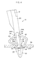
- Fig. 4 is a front view of the coil clamp relating to the present embodiment in a state in which the coil clamp is engaged with the mounting hole and inclined.
- Fig. 5 is a front view of the coil clamp relating to the present embodiment in a state in which the coil clamp is engaged with a bracket which is thick and has a large diameter.
- Fig. 6 is a front view of the coil clamp relating to the present embodiment in a state in which the coil clamp is engaged with a bracket which is thick and has a small diameter.
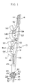
- Fig. 7 is a schematic view of the coil clamp relating to the present embodiment in the state in which the coil clamp is used.
- Fig. 8 is a side view of the coil clamp relating to the present embodiment.
- Fig. 9 is a side view of the coil clamp relating to the present embodiment.
- Fig. 10 is a front view of the coil clamp relating to the present embodiment.
- Fig. 11 is a plan view of the coil clamp relating to the present embodiment.
- Fig. 12 is a bottom view of the coil clamp relating to the present embodiment.
- Fig. 13 is a schematic view of a cable clamp relating to the present embodiment in a state in which the cable clamp is used.
- Fig. 14 is a cross-sectional view of a conventional engaging structure.
- Fig. 15 is a cross-sectional view of a conventional engaging structure.
- the coil clamp 10 is provided with a flexible, elongated, thin plate-shaped frame 12.
- the transverse groove portions 14 are nipped by fingers, and a distal end side of the frame 12 is inserted through a gap between a housing 16 and a cathode-ray tube 18 (see Fig. 7).
- This coil clamp can be integrally formed by a flexible material such as resin.
- a thick plate-shaped portion 20 is formed at a distal end side of the frame 12.
- a groove 22 is formed along the transverse direction of the frame 12.
- the bottom of the groove 22 is wider than the width thereof and the groove 22 is cut in the form of an arc.
- the bottom sides of the remaining groove walls 24 are thin-walled portions 24A.
- narrow leg pieces 26 are extended outwardly from the bottom walls 24 substantially parallel to each other and form an elongated, or lengthwise, gap 28 therebetween.
- the widths of the distal end portions of the leg pieces 26 are slightly increased and are gradually narrowed towards the distal end of the frame 12.
- the distal end portions of the leg pieces 26 are tapered and connected so as to form an anchor portion 30.
- the outer surface of the anchor portion 30 is gradually thickened towards the proximal end sides of the leg pieces 26 so as to form engaging portions 32, which are engaged with the peripheral edge of the mounting hole 36, at the end of the leg pieces 26 (see Figs. 8 and 9).
- the groove walls 24 and the leg pieces 26 form a leg body.
- leg pieces 26 which are slightly narrower than the engaging portions 32, diagonally project with respect to the leg pieces 26 in the direction of separating from each other. Accordingly, the overall contour of the leg pieces 26 and the anchor portion 30 is formed so as to be substantially shaped as an arrow.
- the interval of the gap 28 is elastically narrowed so that the press-fitting becomes easy.
- the range over which the diameter of the anchor portion 30 reduces is kept constant.
- the interval between the thin-walled portions 26A of the leg pieces 26 reduces.
- the portions of the leg pieces 26, which are retained in the mounting hole 36, are thin-walled portions 26A. Accordingly, the leg pieces 26 are flexible and the interval thereof can easily increase and decrease.
- elastic plates 40 diagonally project toward the distal ends of the leg pieces 26 in the direction of separating from each other. At the intermediate portions, the elastic plates 40 bend toward the leg pieces 26. The distal ends of the elastic plates 40 oppose free ends of the pawl pieces 34 at a predetermined interval (the interval which is slightly smaller the minimum thickness of the bracket 38 to be used).
- the cross-sectional configuration of the distal end portions (the free ends) of the elastic plates 40 is substantially formed in the shape of an arc.
- the arc-shaped distal end portions of the elastic plates 40 elastically contact the surface of the bracket 38 so as to apply to the anchor portion 30 the force which withdraws the anchor portion 30.
- the force which outwardly presses and expands the groove walls 24 generates so that the interval between the thin-walled portions 26A of the leg pieces 26, which are retained in the mounting hole 36, increases.
- a pair of pawl pieces 34 press the back surface of the bracket 38 so as to be separate from each other. Due to the separation of the pawl pieces 34, the thin-walled portions 26A are pulled by the pawl pieces 34 so as to enlarge the gap 28.
- two arc-shaped clamp plates 41 project outwardly at a predetermined interval so as to respectively form a retaining space 44, which retains degaussing coils 42 between the clamp plate 41 and the side surface of the frame 12.
- stay plate 46 is provided and is connected to the frame 12.
- an elongated stay plate 48 is provided along the longitudinal direction of the frame 12 and is used for reinforcing the rigidity of the frame 12.
- a guide piece 50 which inclines in the direction of separating from the frame 12, extends outwardly.
- a pressing plate 52 diagonally extends toward the frontage of the retaining space 44.
- a V-shaped guide portion which guides the degaussing coils 42 into the retaining space 44, is formed by the pressing plate 52 and the guide piece 50.
- a triangular plate 54 is provided at the end surface of the pressing plate 52 in the transverse direction thereof so as to close a portion of the triangular gap formed by the pressing plate 52 and the frame 12.
- the transverse groove portions 14 of the coil clamp 10 are nipped by fingers, and through the gap between the housing 16 and the cathode-ray tube 18, the anchor portion 30 is press-fitted into the mounting hole 36 punched at the bracket 38 (see Fig. 7).
- the anchor portion 30 passes through the mounting hole 36 while decreasing the diameter thereof, the anchor portion 30 elastically returns to its original shape, so that the engaging portions 32 of the anchor portion 30 and the pawl pieces 34, which are projected outwardly from the engaging portions 32, are engaged with the peripheral edge of the mounting hole 36.
- the degaussing coils 42 are pressed into the retaining space 44 formed by the clamp plate 41 and the frame 12 while the degaussing coils 42 are wound around the outer peripheral surface of the cathode-ray tube 18.
- the coil clamp 10 needs to be inclined so as to facilitate the pressing of the degaussing coils 42 into the retaining space 44.
- the frame 12 is easily inclined while the leg pieces 26 slightly narrow the width of the gap 28.
- the elastic plates 40 are bent and do not support the frame 12, the frame 12 can be easily inclined.
- the degaussing coils 42 are prevented by the end portion 54A of the triangular plate 54 from entering into the triangular gap formed between the pressing plate 52 and the frame 12, the position around which the degaussing coils 42 are wound does not deviate and the degaussing coils 42 can be secured at a predetermined position.
- the anchor portion 30 is withdrawn by the urging force of the elastic plates 40, so that the upper and the lower portions of the thin-walled portions 26A, which diameters thereof are reduced so as to correspond to the diameter of the mounting hole 102, rise. In a state in which the inclination is allowed, the thin-walled portions 26A are firmly retained in the mounting hole 102.
- the cable clamp 60 is provided with a long plate-shaped base 62. At the central portion of the base 62, a support 64 whose side surfaces are formed in the shape of an arc is provided. On both sides of the support 64, elastic retaining pieces 66 whose inner sides are formed in the shape of an arc are provided so as to oppose the support 64 and form circular spaces with the support 64. The upper portion of the support 64 and the elastic retaining pieces 66 is opened so that cables 68 can be press-fitted thereinto.
- the cable clamp 60 is mounted to a mounting plate 70 and an opening/closing door 72.
- the opening/closing door 72 is connected to the mounting plate 70 by hinges 74 so as to be pivotable.
- the cables 68 when the opening/closing door 70 is pivoted, the cables 68 also swing. However, by disposing the cables 68 in the swinging direction thereof so as to increase and decrease the gap 28 of the leg pieces 26, the swing is allowed and excessive force does not act on the cables 68. Moreover, because the pawl pieces 34 are pressed and expanded so that the abdomen portion 34A widely abuts the back surfaces of the mounting plate 70 and the opening/closing door 72, the anchor portion 30 is not withdrawn from the mounting plate 70.
- the engaging structure of the retainer relating to the present invention is not limited to the above-described coil clamp 10 and the cable clamp 60 and can be applied to any structure provided that the anchor portion thereof is inclined.
- the present invention can conform to changes in the thickness of the mounting plate and changes in the diameter of the mounting hole. Further, the engaging portion of the present invention can be inclined and is not withdrawn from the mounting hole.
Landscapes
- Engineering & Computer Science (AREA)
- General Engineering & Computer Science (AREA)
- Mechanical Engineering (AREA)
- Multimedia (AREA)
- Signal Processing (AREA)
- Insertion Pins And Rivets (AREA)
Priority Applications (1)
| Application Number | Priority Date | Filing Date | Title |
|---|---|---|---|
| EP95111842A EP0756094A1 (fr) | 1995-07-27 | 1995-07-27 | Structure d'engagement d'un élément de fixation |
Applications Claiming Priority (1)
| Application Number | Priority Date | Filing Date | Title |
|---|---|---|---|
| EP95111842A EP0756094A1 (fr) | 1995-07-27 | 1995-07-27 | Structure d'engagement d'un élément de fixation |
Publications (1)
| Publication Number | Publication Date |
|---|---|
| EP0756094A1 true EP0756094A1 (fr) | 1997-01-29 |
Family
ID=8219473
Family Applications (1)
| Application Number | Title | Priority Date | Filing Date |
|---|---|---|---|
| EP95111842A Withdrawn EP0756094A1 (fr) | 1995-07-27 | 1995-07-27 | Structure d'engagement d'un élément de fixation |
Country Status (1)
| Country | Link |
|---|---|
| EP (1) | EP0756094A1 (fr) |
Cited By (1)
| Publication number | Priority date | Publication date | Assignee | Title |
|---|---|---|---|---|
| WO2008053375A1 (fr) * | 2006-11-02 | 2008-05-08 | Grundig Elektronik Anonim Sirketi | Bobine |
Citations (8)
| Publication number | Priority date | Publication date | Assignee | Title |
|---|---|---|---|---|
| GB1075301A (en) * | 1964-02-12 | 1967-07-12 | Ft Products Ltd | Improvements in and relating to fasteners |
| US3777052A (en) * | 1971-03-04 | 1973-12-04 | Richco Plastic Co | Support for circuit boards |
| DE3230852A1 (de) * | 1981-08-27 | 1983-03-10 | Kitagawa Industries Co. Ltd., Nagoya, Aichi | Kabelschelle |
| JPS58158490U (ja) | 1982-04-16 | 1983-10-22 | 北川工業株式会社 | 固定具 |
| FR2536237A1 (fr) * | 1982-11-12 | 1984-05-18 | Kitagawa Ind Co Ltd | Entretoise pour plaquettes de connexion et structure obtenue par assemblage avec de telles entretoises |
| US5035560A (en) * | 1987-09-24 | 1991-07-30 | Nifco, Inc. | Clip |
| US5324151A (en) * | 1993-03-29 | 1994-06-28 | United Technologies Automotive, Inc. | Anti-rotational fastener |
| GB2289714A (en) * | 1994-05-27 | 1995-11-29 | Nifco Inc | Engaging structure of a retainer |
-
1995
- 1995-07-27 EP EP95111842A patent/EP0756094A1/fr not_active Withdrawn
Patent Citations (8)
| Publication number | Priority date | Publication date | Assignee | Title |
|---|---|---|---|---|
| GB1075301A (en) * | 1964-02-12 | 1967-07-12 | Ft Products Ltd | Improvements in and relating to fasteners |
| US3777052A (en) * | 1971-03-04 | 1973-12-04 | Richco Plastic Co | Support for circuit boards |
| DE3230852A1 (de) * | 1981-08-27 | 1983-03-10 | Kitagawa Industries Co. Ltd., Nagoya, Aichi | Kabelschelle |
| JPS58158490U (ja) | 1982-04-16 | 1983-10-22 | 北川工業株式会社 | 固定具 |
| FR2536237A1 (fr) * | 1982-11-12 | 1984-05-18 | Kitagawa Ind Co Ltd | Entretoise pour plaquettes de connexion et structure obtenue par assemblage avec de telles entretoises |
| US5035560A (en) * | 1987-09-24 | 1991-07-30 | Nifco, Inc. | Clip |
| US5324151A (en) * | 1993-03-29 | 1994-06-28 | United Technologies Automotive, Inc. | Anti-rotational fastener |
| GB2289714A (en) * | 1994-05-27 | 1995-11-29 | Nifco Inc | Engaging structure of a retainer |
Cited By (1)
| Publication number | Priority date | Publication date | Assignee | Title |
|---|---|---|---|---|
| WO2008053375A1 (fr) * | 2006-11-02 | 2008-05-08 | Grundig Elektronik Anonim Sirketi | Bobine |
Similar Documents
| Publication | Publication Date | Title |
|---|---|---|
| US5601260A (en) | Engaging structure of retainer | |
| JP3386241B2 (ja) | クリップ | |
| EP0762543B1 (fr) | Clavette de connexion électrique ayant des saillies de rétention | |
| JP2582404Y2 (ja) | クリップ | |
| US4455715A (en) | Cable clamp | |
| EP0660018A1 (fr) | Bande | |
| JP2002276633A (ja) | 樹脂クリップ | |
| JP2003111250A (ja) | グロメット | |
| KR960705704A (ko) | 시트벨트장치용 벨트결합금구 및 그 제조방법 | |
| JP4722458B2 (ja) | 車両アクセサリ固定用金属クリップ及びそれを用いた車両アクセサリ取付け構造 | |
| EP0995614B1 (fr) | Clip | |
| JP2003054508A (ja) | ストラップを突刺す係止装置を備える低挿入力のケーブルタイ | |
| EP0756094A1 (fr) | Structure d'engagement d'un élément de fixation | |
| JP2566920Y2 (ja) | バンドクランプ | |
| JP3363199B2 (ja) | 端子台 | |
| JP2810325B2 (ja) | クリップ | |
| JPH07190029A (ja) | クリップ | |
| JPH06274771A (ja) | 火災感知器の自己鎖錠端子装置 | |
| JP2000037980A (ja) | クリップ | |
| JPS6341345Y2 (fr) | ||
| JP2736766B2 (ja) | 固着具 | |
| JPS62249860A (ja) | テ−プカツテイング装置 | |
| JPS6347283Y2 (fr) | ||
| JPH0327003Y2 (fr) | ||
| JP2557091Y2 (ja) | 端子装置 |
Legal Events
| Date | Code | Title | Description |
|---|---|---|---|
| PUAI | Public reference made under article 153(3) epc to a published international application that has entered the european phase |
Free format text: ORIGINAL CODE: 0009012 |
|
| AK | Designated contracting states |
Kind code of ref document: A1 Designated state(s): DE FR |
|
| 17P | Request for examination filed |
Effective date: 19970123 |
|
| 17Q | First examination report despatched |
Effective date: 19980630 |
|
| STAA | Information on the status of an ep patent application or granted ep patent |
Free format text: STATUS: THE APPLICATION IS DEEMED TO BE WITHDRAWN |
|
| 18D | Application deemed to be withdrawn |
Effective date: 19981111 |