EP0753697A1 - Vorrichtung zur Schnellverbindung einer Rohrleitung mit einem Anschlussstück, insbesondere für einen Wärmetauscher, sowie ein mit dieser Vorrichtung bestückter Wärmetauscher - Google Patents
Vorrichtung zur Schnellverbindung einer Rohrleitung mit einem Anschlussstück, insbesondere für einen Wärmetauscher, sowie ein mit dieser Vorrichtung bestückter Wärmetauscher Download PDFInfo
- Publication number
- EP0753697A1 EP0753697A1 EP96401406A EP96401406A EP0753697A1 EP 0753697 A1 EP0753697 A1 EP 0753697A1 EP 96401406 A EP96401406 A EP 96401406A EP 96401406 A EP96401406 A EP 96401406A EP 0753697 A1 EP0753697 A1 EP 0753697A1
- Authority
- EP
- European Patent Office
- Prior art keywords
- ring
- end piece
- tubing
- tube
- annular groove
- Prior art date
- Legal status (The legal status is an assumption and is not a legal conclusion. Google has not performed a legal analysis and makes no representation as to the accuracy of the status listed.)
- Withdrawn
Links
Images

Classifications
-
- F—MECHANICAL ENGINEERING; LIGHTING; HEATING; WEAPONS; BLASTING
- F16—ENGINEERING ELEMENTS AND UNITS; GENERAL MEASURES FOR PRODUCING AND MAINTAINING EFFECTIVE FUNCTIONING OF MACHINES OR INSTALLATIONS; THERMAL INSULATION IN GENERAL
- F16L—PIPES; JOINTS OR FITTINGS FOR PIPES; SUPPORTS FOR PIPES, CABLES OR PROTECTIVE TUBING; MEANS FOR THERMAL INSULATION IN GENERAL
- F16L37/00—Couplings of the quick-acting type
- F16L37/08—Couplings of the quick-acting type in which the connection between abutting or axially overlapping ends is maintained by locking members
- F16L37/084—Couplings of the quick-acting type in which the connection between abutting or axially overlapping ends is maintained by locking members combined with automatic locking
- F16L37/088—Couplings of the quick-acting type in which the connection between abutting or axially overlapping ends is maintained by locking members combined with automatic locking by means of a split elastic ring
- F16L37/0885—Couplings of the quick-acting type in which the connection between abutting or axially overlapping ends is maintained by locking members combined with automatic locking by means of a split elastic ring with access to the split elastic ring from a radial or tangential opening in the coupling
-
- F—MECHANICAL ENGINEERING; LIGHTING; HEATING; WEAPONS; BLASTING
- F16—ENGINEERING ELEMENTS AND UNITS; GENERAL MEASURES FOR PRODUCING AND MAINTAINING EFFECTIVE FUNCTIONING OF MACHINES OR INSTALLATIONS; THERMAL INSULATION IN GENERAL
- F16L—PIPES; JOINTS OR FITTINGS FOR PIPES; SUPPORTS FOR PIPES, CABLES OR PROTECTIVE TUBING; MEANS FOR THERMAL INSULATION IN GENERAL
- F16L37/00—Couplings of the quick-acting type
- F16L37/56—Couplings of the quick-acting type for double-walled or multi-channel pipes or pipe assemblies
-
- F—MECHANICAL ENGINEERING; LIGHTING; HEATING; WEAPONS; BLASTING
- F28—HEAT EXCHANGE IN GENERAL
- F28F—DETAILS OF HEAT-EXCHANGE AND HEAT-TRANSFER APPARATUS, OF GENERAL APPLICATION
- F28F9/00—Casings; Header boxes; Auxiliary supports for elements; Auxiliary members within casings
- F28F9/02—Header boxes; End plates
- F28F9/0246—Arrangements for connecting header boxes with flow lines
- F28F9/0256—Arrangements for coupling connectors with flow lines
- F28F9/0258—Arrangements for coupling connectors with flow lines of quick acting type, e.g. with snap action
-
- Y—GENERAL TAGGING OF NEW TECHNOLOGICAL DEVELOPMENTS; GENERAL TAGGING OF CROSS-SECTIONAL TECHNOLOGIES SPANNING OVER SEVERAL SECTIONS OF THE IPC; TECHNICAL SUBJECTS COVERED BY FORMER USPC CROSS-REFERENCE ART COLLECTIONS [XRACs] AND DIGESTS
- Y10—TECHNICAL SUBJECTS COVERED BY FORMER USPC
- Y10S—TECHNICAL SUBJECTS COVERED BY FORMER USPC CROSS-REFERENCE ART COLLECTIONS [XRACs] AND DIGESTS
- Y10S285/00—Pipe joints or couplings
- Y10S285/914—Irreversible
Definitions
- the invention relates to a quick coupling device for connecting a tubing and a nozzle, in particular for a heat exchanger, as well as a heat exchanger equipped with such a device.
- It relates more particularly to a device for connecting a tubing with an annular groove and a nozzle, this nozzle being able to be formed at the end of a conduit, for example a flexible conduit, or to receive such a conduit by fitting.
- connection device can be used in particular to form part of a circuit for cooling the engine, or for heating the passenger compartment, of a motor vehicle.
- a connection device is generally paired to allow the connection of the pipes of a heat exchanger, which are used for the entry and exit of a heat-transfer fluid, and of two corresponding nozzles which are usually connected to flexible conduits suitable for transporting the heat transfer fluid between the heat exchanger and other elements of the fluid circuit.
- the invention provides a solution to this problem.
- a quick coupling device of the type defined in the introduction which comprises a ring which is suitable for being threaded around the tube and which is provided with a first locking means suitable for engaging in the annular groove. of the tubing for immobilizing the ring relative to the tubing, and in which the endpiece comprises a housing arranged to receive one end of the tubing as well as the ring, with interposition of a sealing means between the endpiece and the tubing, the tip being provided with a second locking means capable of immobilizing the tip relative to the ring.
- connection of the tubing and the end piece is effected by means of a ring which comes to a standstill relative to the tubing on the one hand, and relative to the end piece on the other hand, with interposition of a sealing means.
- the ring comprises a deformable annular body interrupted by a slot
- the first locking means comprises an annular rib formed internally on the ring body and interrupted by the slot, this rib being suitable for engage in the annular groove of the tubing by deformation of the ring body.
- the ring comprises a continuous annular body
- the first locking means comprises a pin suitable for passing through the ring body from the outside to engage in the annular groove of the tubing.
- this pin comprises two branches which are substantially parallel to each other and capable of passing through two passages of the ring body in order to engage in two diametrically opposite regions of the groove of the tube, these two branches being joined together by a core suitable for not not protrude from the outer periphery of the ring.
- the ring may include at least one indexing mark formed at its periphery and adapted to cooperate with a corresponding housing of the end piece to allow the immobilization of the ring and the end piece in a determined position.
- this ring includes two diametrically opposite indexing marks and of different configuration to serve as polarizers.
- the ring has a body externally delimited by a frustoconical front wall and a cylindrical rear wall, so that, after immobilization of the ring around the tube, the end of the tube projects beyond the ring.
- the housing of the end piece is defined by a first cylindrical wall suitable for housing the end of the tube, by a frustoconical wall suitable for housing the frustoconical wall of the ring and by a second cylindrical wall suitable for housing the cylindrical wall of the ring.
- the end piece comprises an internal groove capable of accommodating an O-ring seal to cooperate with the end of the tubing.
- the second locking means is advantageously produced in the form of a deformable rod suitable for at least partially surrounding the end piece and comprising two opposite parts resiliently biased towards each other, these two opposite parts being suitable for passing through two opposite slots of the end piece to engage in an annular groove formed at the periphery of the ring.
- This deformable rod is preferably made from a metal wire and it includes a handle.
- the tip may include a stepped part for receiving a flexible conduit.
- the tubing is metallic, for example aluminum, while the ring and the end piece are made of plastic.
- the device comprises two rings capable of ensuring the simultaneous connection of two tubes and two end pieces, these rings being connected together by a flexible link allowing mutual movement of the two rings.
- the two pipes are advantageously inlet pipes and outlet pipes for heat transfer fluid from a heat exchanger.
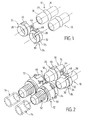
- the device of Figures 1 and 2 is intended to connect two pipes 10, of substantially parallel axes, respectively to two end pieces 12 ( Figure 2).
- the pipes 10, made for example of a metal such as aluminum, constitute the inlet and outlet pipes of a heat exchanger, not shown.
- This heat exchanger is part of a circulation of heat transfer fluid, for example of an engine cooling circuit, or heating of the passenger compartment, of a motor vehicle.
- the end pieces 12 are suitable for being connected respectively to two flexible conduits 14 (shown in dashed lines in FIG. 2) for connecting the heat exchanger to other elements of the circulation circuit of the heat transfer fluid.
- each tube 10 has a shape of revolution around an axis X-X.
- the tubing 10 comprises a body 16, a free end 18 and an annular groove 20 formed between the body 16 and the free end 18. Between the groove 20 and the body 16 is also formed a bead 22. The end 18 is ends with an annular shoulder 24.
- connection device comprises two paired rings 26 suitable for being threaded around the respective tubes 10.
- Each ring 26 comprises an annular body of deformable material, for example plastic, interrupted by a slot 28 ( Figures 1, 2, 5 and 6 ), which extends in a direction generally parallel to the axis.
- the body of the ring 26 is delimited externally by a frustoconical front wall 30 and by a cylindrical rear wall 32, in which an annular groove 34 is formed ( Figures 1, 2 and 3).
- the body of the ring is delimited internally by a front cylindrical wall 36, a rear cylindrical wall 38 and an intermediate cylindrical wall 40, of smaller diameter than the walls 36 and 38 (FIG. 3).
- the diameter of the wall 38 is substantially equal to the diameter of the bead 22, so that the latter can come to bear against a shoulder 42 formed between the cylindrical walls 38 and 40 ( Figure 3).
- the ring 26 can be expanded radially and then threaded around the tube until the shoulder 42 comes against the bead 22. Then, the ring contracts radially, due to its own elasticity, so that the wall cylindrical 40 enters the groove 20 of the tubing, as seen in FIG. 4.
- the rings 26 are connected together by a flexible link 44 in the shape of a U allowing mutual movement of the two rings perpendicular to their respective axes.
- each of the rings 26 has two indexing pins 46 and 48, diametrically opposite, and of different configuration to serve as polarizers. These pins are projecting lugs intended to cooperate in corresponding recesses in the end pieces 12, for example in a recess 49 (FIG. 2).
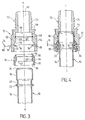
- Each end piece 12 is preferably made of plastic and comprises, as can be seen better in FIG. 3, a body 50 extended by a tubular part 52 having a stepped relief 54 intended to be capped by a conduit 14.
- the body 50 is delimited externally by a cylindrical wall 56 which is connected to the tubular part 52 by a shoulder 58.
- the end piece 12 internally delimits a housing 60 arranged to receive the end 18 of the tubing as well as the ring 26 previously threaded on the tubing.
- This housing 60 communicates with an axial passage 62 of the tubular part 52 (FIG. 3).
- the housing 60 is delimited by a cylindrical wall 64 of diameter substantially equal to that of the end 18 of the tubing, this cylindrical wall 64 being connected to the passage 62 by a shoulder 66.
- This tubular wall 64 comprises an annular groove suitable for receiving an O-ring seal 68.
- the housing 60 is further delimited by a frustoconical wall 70 which is connected, on the one hand to the wall 64, and on the other hand to a cylindrical wall 72 opening outwards.
- the walls 70 and 72 have shapes which adapt respectively to the walls 30 and 32 of the ring 26.
- Each end piece 12 is provided with a locking member 74 intended to immobilize the end piece with respect to the ring after their mutual engagement.
- the locking member 74 is a deformable rod of metal wire suitable for at least partially surrounding the end piece 12 and comprising two opposite parts 76 resiliently biased towards one another (FIG. 3). These two parts 76 are suitable for passing through two opposite slots 78 formed in the body 50 of the end piece 12 to establish a communication passage between the outer wall 56 and the inner wall 72. Furthermore, the ring 74 includes a handle 80 for facilitate its actuation. The two opposite parts 76 are suitable for engaging in the external groove 34 of the ring 26 to immobilize the ring and the end piece mutually.
- the two rings 26 are presented opposite and in the axis of the ends 18 of the pipes 10 (FIG. 1).
- the rings are then threaded around the ends 18, which causes their radial expansion, then their contraction, to arrive in the position of FIG. 2.
- the two rings are immobilized axially on the pipes and also in rotation, from the makes the link 14.
- the two end pieces 12 are presented opposite and in the axis of the pipes 10 previously fitted with the rings 26, as shown in FIG. 2.
- the end pieces 12 are moved axially and thus come to cover the ends 18 of the pipes 10, as well as the rings 26, to arrive in the position shown in FIG. 4.
- the locking member 74 s' automatically spreads, then the parts 76 approach each other to come into the groove 34 of the ring 26. This gives a locking of the ring, on the one hand with the tubing, and on the other hand with the mouthpiece.
- the seal 68 provides a seal between the end 18 of the tubing and the end piece.
- the tubing 10 again includes an annular groove 20; however, unlike the previous embodiment, there is no provision for a bead between the groove 20 and the body 16 of the tube.
- the ring 26 comprises a continuous annular body, therefore not split, and the means for locking of the ring is here constituted by a pin 90 produced in the form of a folded metal wire.
- This pin comprises two branches 92 which are substantially parallel to each other (FIG. 7), suitable for passing through the ring body, from the outside, to engage in the annular groove 20 of the tubing.
- the two branches 92 are provided to pass through two passages 94 formed in the thickness of the ring body, so as to engage in two diametrically opposite regions of the groove 20.
- the two branches 92 are joined together to a core 96 of generally curved shape, by means of two segments 98 parallel to each other. These two segments 98 are suitable for fitting into two recesses 100 parallel to each other and to the axis of the ring 26, which are formed in the cylindrical rear wall 32 of the ring body.
- the ring 26 must first be fitted around the tube 10, then the pin 90 is introduced laterally so that its two branches 92 cause locking.
- the spindle is completely inserted ( Figure 8)
- the ring is immobilized relative to the tubing and the core 96 of the spindle is supported behind a rear face 102 of the ring 26 ( Figure 7).
- connection device it is possible to disassemble the connection device by first releasing the locking ring 74 from the end piece, so as to allow the end piece to be separated tubing, then remove the ring, if necessary.
- the invention can be used very particularly for the connection of heat exchangers of motor vehicles.
Landscapes
- Engineering & Computer Science (AREA)
- General Engineering & Computer Science (AREA)
- Mechanical Engineering (AREA)
- Physics & Mathematics (AREA)
- Thermal Sciences (AREA)
- Quick-Acting Or Multi-Walled Pipe Joints (AREA)
Applications Claiming Priority (2)
| Application Number | Priority Date | Filing Date | Title |
|---|---|---|---|
| FR9507784A FR2736135B1 (fr) | 1995-06-28 | 1995-06-28 | Dispositif de raccord rapide entre une tubulure et un embout, notamment pour echangeur de chaleur, et echangeur de chaleur equipe d'un tel dispositif |
| FR9507784 | 1995-06-28 |
Publications (1)
| Publication Number | Publication Date |
|---|---|
| EP0753697A1 true EP0753697A1 (de) | 1997-01-15 |
Family
ID=9480478
Family Applications (1)
| Application Number | Title | Priority Date | Filing Date |
|---|---|---|---|
| EP96401406A Withdrawn EP0753697A1 (de) | 1995-06-28 | 1996-06-25 | Vorrichtung zur Schnellverbindung einer Rohrleitung mit einem Anschlussstück, insbesondere für einen Wärmetauscher, sowie ein mit dieser Vorrichtung bestückter Wärmetauscher |
Country Status (3)
| Country | Link |
|---|---|
| US (1) | US5860677A (de) |
| EP (1) | EP0753697A1 (de) |
| FR (1) | FR2736135B1 (de) |
Cited By (8)
| Publication number | Priority date | Publication date | Assignee | Title |
|---|---|---|---|---|
| DE10316757A1 (de) * | 2003-04-10 | 2004-10-28 | Behr Gmbh & Co. Kg | Anschluß für einen Wärmetauscher, insbesondere für ein Kraftfahrzeug |
| US7914049B2 (en) | 2006-03-02 | 2011-03-29 | Gambro Lundia Ab | Hydraulic connector and a hydraulic circuit incorporating the connector |
| ITUD20120012A1 (it) * | 2012-01-30 | 2013-07-31 | Dynamic Technologies S P A | Organo di trasferimento fluidi e relativo metodo di realizzazione |
| CN107031847A (zh) * | 2015-11-24 | 2017-08-11 | 哈米尔顿森德斯特兰德公司 | 机舱供应管道 |
| FR3064712A1 (fr) * | 2017-03-30 | 2018-10-05 | Autotube Aktiebolag | Procede de fabrication d’un agencement fluidique et agencement fluidique associe |
| WO2021126215A1 (en) * | 2019-12-19 | 2021-06-24 | Oetiker Ny, Inc. | Fluid connector with an expansion ring |
| AT17372U1 (de) * | 2021-01-20 | 2022-02-15 | Henn Gmbh & Co Kg | Gegensteckverbinder zum Verbinden von Bauteilen für flüssige oder gasförmige Medien, sowie eine Steckerbaugruppe und ein Verfahren zum Herstellen eines derartigen Gegensteckverbinders |
| AT525973A4 (de) * | 2022-07-26 | 2023-10-15 | Henn Gmbh & Co Kg | Steckverbinder zum Verbinden von Leitungen für flüssige oder gasförmige Medien |
Families Citing this family (47)
| Publication number | Priority date | Publication date | Assignee | Title |
|---|---|---|---|---|
| AUPP855099A0 (en) * | 1999-02-09 | 1999-03-04 | Resmed Limited | Gas delivery connection assembly |
| US6796308B2 (en) | 1998-12-09 | 2004-09-28 | Resmed Limited | Mask cushion and frame assembly |
| EP1173700A4 (de) | 1999-04-06 | 2003-05-02 | Optimum Innovations Australia | Verbindungsstück für flüssigkeitsleitungen |
| US6447017B1 (en) | 1999-10-29 | 2002-09-10 | The Gates Corporation | Fluid coupling and assembly |
| US6435565B2 (en) * | 2000-07-18 | 2002-08-20 | Bks Company Llc | Clamp for closely spaced pipes |
| DE20017940U1 (de) | 2000-10-19 | 2000-12-28 | MAP Medizintechnik für Arzt und Patient GmbH & Co KG, 82152 Planegg | Atemmaske zur Zufuhr eines Atemgases zu einem Maskenanwender sowie Ableitungseinrichtung zur Ableitung von Atemgas |
| US6682100B2 (en) * | 2001-02-15 | 2004-01-27 | Parker-Hannifin Corporation | Connection block with clip |
| US20030001384A1 (en) * | 2001-06-28 | 2003-01-02 | Carroll James E. | Seal cap and connector assembly |
| ATE390945T1 (de) | 2001-09-07 | 2008-04-15 | Resmed Ltd | Maskenanordnung |
| US6637779B2 (en) | 2001-10-18 | 2003-10-28 | Itt Manufacturing Enterprises, Inc. | Fluid quick connector with grooved endform |
| DE50214539D1 (de) | 2001-10-22 | 2010-08-26 | Map Medizin Technologie Gmbh | Medizinische Maske |
| DE10151984C5 (de) | 2001-10-22 | 2008-07-17 | Map Medizin-Technologie Gmbh | Applikationsvorrichtung für eine Atemmaskenanordnung |
| DE10201682A1 (de) | 2002-01-17 | 2003-07-31 | Map Medizin Technologie Gmbh | Atemmaskenanordnung |
| US6609732B1 (en) | 2002-02-01 | 2003-08-26 | General Motors Corporation | Quick connect multi-hose connector |
| US8113547B2 (en) * | 2002-03-22 | 2012-02-14 | Cooper Standard Automotive Inc. | Snap mount fluid quick connector |
| DE50204467D1 (de) * | 2002-05-04 | 2006-02-16 | Ti Automotive Fuldabrueck Gmbh | Rohrkupplung für Rohrleitungen |
| US6776225B2 (en) * | 2002-06-13 | 2004-08-17 | Delphi Technologies, Inc. | Heat exchanger assembly |
| EP3009159B1 (de) * | 2002-09-06 | 2020-02-19 | ResMed Pty Ltd | Stirnpolster für atemmaske |
| DE10304074B3 (de) * | 2003-01-31 | 2004-02-05 | A. Raymond & Cie | Lösbare Steckverbindung für Hochdruckleitungen |
| JP4299646B2 (ja) * | 2003-12-05 | 2009-07-22 | 株式会社パイオラックス | 管継手 |
| DE102004028655A1 (de) * | 2004-06-15 | 2006-01-05 | Behr Gmbh & Co. Kg | Wärmeübertrager, insbesondere gelöteter Heizkörper |
| CN106110464B (zh) | 2004-06-16 | 2019-03-12 | 瑞思迈有限公司 | 呼吸面罩组件的软垫 |
| US7438328B2 (en) * | 2005-03-25 | 2008-10-21 | Tokai Rubber Industries, Ltd. | Quick connector |
| NL1029030C2 (nl) * | 2005-05-12 | 2006-11-14 | Actuant Corp | Hydraulisch systeem. |
| DE202005009018U1 (de) * | 2005-06-09 | 2006-10-19 | Voss Automotive Gmbh | Anschlussvorrichtung mit Medienleitungen |
| DE102005050490A1 (de) * | 2005-10-21 | 2007-04-26 | Henn Gmbh & Co. Kg | Steckverbindung an Rohren und Schläuchen mit einem Rohrrastring |
| DE102005055046A1 (de) * | 2005-11-16 | 2007-05-24 | J. Eberspächer GmbH & Co. KG | Übersprecher für eine Abgasanlage |
| DE102006002565A1 (de) * | 2006-01-05 | 2007-07-12 | Alfred Kärcher Gmbh & Co. Kg | Kupplungsteil für Steckverbinderanordnung |
| DE102006002564A1 (de) * | 2006-01-05 | 2007-07-12 | Alfred Kärcher Gmbh & Co. Kg | Steckteil für Steckverbinderanordnung |
| US8555463B1 (en) * | 2006-04-18 | 2013-10-15 | Kim E. Laube | Grooming tool with vacuum collection |
| US20080106095A1 (en) * | 2006-11-08 | 2008-05-08 | Harris Richard K | Heater core connector tube |
| JP4864692B2 (ja) * | 2006-12-27 | 2012-02-01 | 株式会社デンソー | 配管継手装置及びその製造方法 |
| US8430365B2 (en) * | 2008-04-03 | 2013-04-30 | Illinois Tool Works Inc. | Tube holding block assembly |
| US11578716B2 (en) | 2010-01-22 | 2023-02-14 | Blue-White Industries, Ltd. | Overmolded tubing assembly and adapter for a positive displacement pump |
| US9909579B2 (en) | 2014-06-09 | 2018-03-06 | Blue-White Industries, Ltd. | Overmolded tubing assembly and adapter for a positive displacement pump |
| FR3001024B1 (fr) * | 2013-01-17 | 2015-12-25 | Delphi Automotive Systems Lux | Dispositif de connexion rapide. |
| US9925350B2 (en) * | 2013-02-19 | 2018-03-27 | Fisher & Paykel Healthcare Limited | Apparatus and method for providing gases to a user |
| US9777720B2 (en) * | 2013-03-14 | 2017-10-03 | Blue-White Industries, Ltd. | High pressure, high flow rate tubing assembly and adapter for a positive displacement pump |
| GB2527551B (en) * | 2014-06-25 | 2019-09-04 | Intersurgical Ag | Respiratory connector |
| DE102015105033A1 (de) | 2015-04-01 | 2016-10-06 | Dr. Ing. H.C. F. Porsche Aktiengesellschaft | Kupplung, insbesondere lösbare Schnellkupplung für Versorgungsleitungen |
| US11098833B2 (en) * | 2016-10-28 | 2021-08-24 | Piolax, Inc. | Quick connector |
| DE102017112530A1 (de) * | 2017-06-07 | 2018-12-13 | Eberspächer Climate Control Systems GmbH & Co. KG | Wärmetauscheranordnung |
| CN110299643B (zh) * | 2019-07-02 | 2025-03-28 | 罗森伯格(常州)电子科技有限公司 | 一种室外防水接头盒 |
| US12202446B2 (en) | 2019-09-12 | 2025-01-21 | A. Raymond Et Cie | Flow control valve and system for cleaning a vehicle surface |
| EP3792535A1 (de) | 2019-09-12 | 2021-03-17 | A. Raymond et Cie | Durchflussregelventil und system zur reinigung einer fahrzeugoberfläche |
| FR3120674B1 (fr) * | 2021-03-09 | 2023-04-28 | Psa Automobiles Sa | Raccord de fluide etanche a raccordement rapide |
| DE102023134483A1 (de) * | 2022-12-15 | 2024-06-20 | Illinois Tool Works Inc. | Mehrfachverbinder |
Citations (4)
| Publication number | Priority date | Publication date | Assignee | Title |
|---|---|---|---|---|
| US2521127A (en) * | 1948-05-08 | 1950-09-05 | Wright Aeronautical Corp | Fluid tight joint |
| DE4037308C1 (en) * | 1990-11-23 | 1992-04-16 | Rasmussen Gmbh, 6457 Maintal, De | Multiple pipeline coupling with interconnected tubular members - which are linked by flexible holder in releasable manner |
| EP0593937A1 (de) * | 1992-09-24 | 1994-04-27 | Showa Aluminum Corporation | Rohrverbindung |
| FR2713305A1 (fr) * | 1993-11-29 | 1995-06-09 | Valeo Thermique Habitacle | Dispositif de raccord rapide pour tubulures d'échangeur de chaleur. |
Family Cites Families (8)
| Publication number | Priority date | Publication date | Assignee | Title |
|---|---|---|---|---|
| US4884829A (en) * | 1986-09-16 | 1989-12-05 | Johannes Schaefer Vorm. Stettiner Schraubenwerke Gmbh & Co. Kg | Plug-in connection for connecting tube and host lines in particular for use in tube-line systems of motor vehicles |
| US5350203A (en) * | 1991-09-10 | 1994-09-27 | Bundy Corporation | Quick connect tubing connector and method of assembly |
| US5538297A (en) * | 1991-09-10 | 1996-07-23 | Bundy Corporation | Quick connect tubing connector |
| JP3104768B2 (ja) * | 1992-03-30 | 2000-10-30 | 臼井国際産業株式会社 | 細径配管接続コネクター |
| FR2691512B1 (fr) * | 1992-05-21 | 1995-11-24 | Hutchinson | Dispositif de raccord rapide, par encliquetage, d'un ensemble d'organes tubulaires a des embouts. |
| FR2694797B1 (fr) * | 1992-08-12 | 1994-11-04 | Hutchinson | Platine et embout pour dispositif de raccordement, dispositif de raccordement et son procédé de réalisation. |
| DE4333273C1 (de) * | 1993-09-30 | 1994-11-10 | Rasmussen Gmbh | Steckkupplung zum Verbinden zweier Fluidleitungen |
| US5551732A (en) * | 1995-02-14 | 1996-09-03 | Proprietary Technology, Inc. | Quick connector |
-
1995
- 1995-06-28 FR FR9507784A patent/FR2736135B1/fr not_active Expired - Fee Related
-
1996
- 1996-06-25 EP EP96401406A patent/EP0753697A1/de not_active Withdrawn
- 1996-06-25 US US08/670,366 patent/US5860677A/en not_active Expired - Fee Related
Patent Citations (4)
| Publication number | Priority date | Publication date | Assignee | Title |
|---|---|---|---|---|
| US2521127A (en) * | 1948-05-08 | 1950-09-05 | Wright Aeronautical Corp | Fluid tight joint |
| DE4037308C1 (en) * | 1990-11-23 | 1992-04-16 | Rasmussen Gmbh, 6457 Maintal, De | Multiple pipeline coupling with interconnected tubular members - which are linked by flexible holder in releasable manner |
| EP0593937A1 (de) * | 1992-09-24 | 1994-04-27 | Showa Aluminum Corporation | Rohrverbindung |
| FR2713305A1 (fr) * | 1993-11-29 | 1995-06-09 | Valeo Thermique Habitacle | Dispositif de raccord rapide pour tubulures d'échangeur de chaleur. |
Cited By (11)
| Publication number | Priority date | Publication date | Assignee | Title |
|---|---|---|---|---|
| DE10316757A1 (de) * | 2003-04-10 | 2004-10-28 | Behr Gmbh & Co. Kg | Anschluß für einen Wärmetauscher, insbesondere für ein Kraftfahrzeug |
| US7914049B2 (en) | 2006-03-02 | 2011-03-29 | Gambro Lundia Ab | Hydraulic connector and a hydraulic circuit incorporating the connector |
| ITUD20120012A1 (it) * | 2012-01-30 | 2013-07-31 | Dynamic Technologies S P A | Organo di trasferimento fluidi e relativo metodo di realizzazione |
| CN107031847A (zh) * | 2015-11-24 | 2017-08-11 | 哈米尔顿森德斯特兰德公司 | 机舱供应管道 |
| FR3064712A1 (fr) * | 2017-03-30 | 2018-10-05 | Autotube Aktiebolag | Procede de fabrication d’un agencement fluidique et agencement fluidique associe |
| FR3064713A1 (fr) * | 2017-03-30 | 2018-10-05 | Autotube Aktiebolag | Procede de fabrication d'un agencement fluidique et agencement fluidique associe |
| US11391403B2 (en) | 2017-03-30 | 2022-07-19 | Akwel Sweden Ab | Manufacturing method for a fluidic arrangement and related fluidic arrangement |
| WO2021126215A1 (en) * | 2019-12-19 | 2021-06-24 | Oetiker Ny, Inc. | Fluid connector with an expansion ring |
| AT17372U1 (de) * | 2021-01-20 | 2022-02-15 | Henn Gmbh & Co Kg | Gegensteckverbinder zum Verbinden von Bauteilen für flüssige oder gasförmige Medien, sowie eine Steckerbaugruppe und ein Verfahren zum Herstellen eines derartigen Gegensteckverbinders |
| AT525973A4 (de) * | 2022-07-26 | 2023-10-15 | Henn Gmbh & Co Kg | Steckverbinder zum Verbinden von Leitungen für flüssige oder gasförmige Medien |
| AT525973B1 (de) * | 2022-07-26 | 2023-10-15 | Henn Gmbh & Co Kg | Steckverbinder zum Verbinden von Leitungen für flüssige oder gasförmige Medien |
Also Published As
| Publication number | Publication date |
|---|---|
| FR2736135B1 (fr) | 1997-08-29 |
| US5860677A (en) | 1999-01-19 |
| FR2736135A1 (fr) | 1997-01-03 |
Similar Documents
| Publication | Publication Date | Title |
|---|---|---|
| EP0753697A1 (de) | Vorrichtung zur Schnellverbindung einer Rohrleitung mit einem Anschlussstück, insbesondere für einen Wärmetauscher, sowie ein mit dieser Vorrichtung bestückter Wärmetauscher | |
| EP1064489B1 (de) | Steck-kupplung für rohre | |
| EP0840867B1 (de) | Vorrichtung zum dichten verbinden eines starren rohrendstückes mit einem schlauch und herstellungsverfahren für eine solche vorrichtung | |
| EP1423636B1 (de) | Vormontierte dichtungsverbindung | |
| EP0890054B1 (de) | Abgedichtete schnell-kupplung | |
| EP0360634B1 (de) | Verbindungseinrichtung zwischen einem Schlauchverbindungsstück und dem starren Rohrende eines Druckmittelkreislaufs | |
| EP0473474B1 (de) | Wasserkasten für einen Hauptwärmetauscher, insbesondere für Kraftfahrzeuge, der einen zweiten Wärmetauscher enthält | |
| FR2715216A1 (fr) | Tube d'échangeur de chaleur, procédé pour sa conformation et échangeur de chaleur comprenant de tels tubes. | |
| FR2588354A1 (fr) | Dispositif de raccordement d'un tuyau elastiquement deformable a un tube rigide | |
| EP0583183A1 (de) | Kupplung zum Verbinden von Leitungen | |
| EP0621432B1 (de) | Vorrichtung zum dichten Verbinden eines Schlauches mit einem starren Rohrende | |
| EP3640516A1 (de) | Schnellkupplungsvorrichtung | |
| FR3064712A1 (fr) | Procede de fabrication d’un agencement fluidique et agencement fluidique associe | |
| EP1056969A1 (de) | Rastverbindung für eine rohrleitung | |
| EP0559505B1 (de) | Vorrichtung zum Verbinden eines Schlauchendes mit dem Ende eines starren Rohres, insbesondere für ein Fahrzeugskühlsystem | |
| EP0473475B1 (de) | Vorrichtung mit einem Wasserkasten für einen ersten Wärmetauscher und einem zweiten Wärmetauscher | |
| FR2742857A1 (fr) | Plaque collectrice pour echangeur de chaleur | |
| EP0338880B1 (de) | Verbindungseinrichtung zwischen einem schlauchartigen Verbindungsteil und einem starren Rohrende für einen Druckmittelkreislauf | |
| FR2644223A1 (fr) | Raccord rapide et procede de montage | |
| EP0480818B1 (de) | Verbesserte Vorrichtung zum Verbinden eines Schlauchendes mit dem Ende eines starren Rohres | |
| EP1413815A1 (de) | Kupplung für zwei Rohre mit aufgeweiteten Enden | |
| FR2772875A1 (fr) | Dispositif de raccordement d'un tuyau souple a une paroi, en particulier d'un echangeur de chaleur de vehicule automobile | |
| FR2665508A1 (fr) | Raccord rapide. | |
| EP1008796A2 (de) | Verbindungsvorrichtung für die lösbare Verbindung eines Rohres an einem Endstück mittels einer koaxialen Hülse | |
| FR2498727A1 (fr) | Embouts perfectionnes pour tuyaux souples |
Legal Events
| Date | Code | Title | Description |
|---|---|---|---|
| PUAI | Public reference made under article 153(3) epc to a published international application that has entered the european phase |
Free format text: ORIGINAL CODE: 0009012 |
|
| AK | Designated contracting states |
Kind code of ref document: A1 Designated state(s): DE ES GB IT |
|
| RIN1 | Information on inventor provided before grant (corrected) |
Inventor name: WURMSER, MARTIN Inventor name: MARTINS, CARLOS |
|
| 17P | Request for examination filed |
Effective date: 19970626 |
|
| 17Q | First examination report despatched |
Effective date: 19990719 |
|
| STAA | Information on the status of an ep patent application or granted ep patent |
Free format text: STATUS: THE APPLICATION IS DEEMED TO BE WITHDRAWN |
|
| 18D | Application deemed to be withdrawn |
Effective date: 20000201 |