EP1008796A2 - Verbindungsvorrichtung für die lösbare Verbindung eines Rohres an einem Endstück mittels einer koaxialen Hülse - Google Patents
Verbindungsvorrichtung für die lösbare Verbindung eines Rohres an einem Endstück mittels einer koaxialen Hülse Download PDFInfo
- Publication number
- EP1008796A2 EP1008796A2 EP99440355A EP99440355A EP1008796A2 EP 1008796 A2 EP1008796 A2 EP 1008796A2 EP 99440355 A EP99440355 A EP 99440355A EP 99440355 A EP99440355 A EP 99440355A EP 1008796 A2 EP1008796 A2 EP 1008796A2
- Authority
- EP
- European Patent Office
- Prior art keywords
- interface
- tube
- sleeve
- socket
- male
- Prior art date
- Legal status (The legal status is an assumption and is not a legal conclusion. Google has not performed a legal analysis and makes no representation as to the accuracy of the status listed.)
- Withdrawn
Links
- 230000002093 peripheral effect Effects 0.000 claims abstract description 4
- 210000000078 claw Anatomy 0.000 claims description 12
- 230000000295 complement effect Effects 0.000 claims description 8
- 239000000463 material Substances 0.000 abstract description 5
- 239000004033 plastic Substances 0.000 abstract description 3
- 229910000831 Steel Inorganic materials 0.000 abstract description 2
- XAGFODPZIPBFFR-UHFFFAOYSA-N aluminium Chemical compound [Al] XAGFODPZIPBFFR-UHFFFAOYSA-N 0.000 abstract description 2
- 229910052782 aluminium Inorganic materials 0.000 abstract description 2
- 239000010959 steel Substances 0.000 abstract description 2
- 239000004411 aluminium Substances 0.000 abstract 1
- 230000008878 coupling Effects 0.000 abstract 1
- 238000010168 coupling process Methods 0.000 abstract 1
- 238000005859 coupling reaction Methods 0.000 abstract 1
- 230000000903 blocking effect Effects 0.000 description 3
- 238000000034 method Methods 0.000 description 3
- 238000007789 sealing Methods 0.000 description 3
- 230000006835 compression Effects 0.000 description 2
- 238000007906 compression Methods 0.000 description 2
- 239000012530 fluid Substances 0.000 description 2
- 239000000446 fuel Substances 0.000 description 2
- 210000000056 organ Anatomy 0.000 description 2
- 239000000243 solution Substances 0.000 description 2
- 238000012546 transfer Methods 0.000 description 2
- 239000004952 Polyamide Substances 0.000 description 1
- 238000004026 adhesive bonding Methods 0.000 description 1
- 238000013461 design Methods 0.000 description 1
- 238000011161 development Methods 0.000 description 1
- 238000002347 injection Methods 0.000 description 1
- 239000007924 injection Substances 0.000 description 1
- 238000003754 machining Methods 0.000 description 1
- 238000004519 manufacturing process Methods 0.000 description 1
- 238000012986 modification Methods 0.000 description 1
- 230000004048 modification Effects 0.000 description 1
- 229920002647 polyamide Polymers 0.000 description 1
- 230000001681 protective effect Effects 0.000 description 1
- 238000013519 translation Methods 0.000 description 1
- 238000003466 welding Methods 0.000 description 1
Images


Classifications
-
- F—MECHANICAL ENGINEERING; LIGHTING; HEATING; WEAPONS; BLASTING
- F16—ENGINEERING ELEMENTS AND UNITS; GENERAL MEASURES FOR PRODUCING AND MAINTAINING EFFECTIVE FUNCTIONING OF MACHINES OR INSTALLATIONS; THERMAL INSULATION IN GENERAL
- F16L—PIPES; JOINTS OR FITTINGS FOR PIPES; SUPPORTS FOR PIPES, CABLES OR PROTECTIVE TUBING; MEANS FOR THERMAL INSULATION IN GENERAL
- F16L37/00—Couplings of the quick-acting type
- F16L37/08—Couplings of the quick-acting type in which the connection between abutting or axially overlapping ends is maintained by locking members
- F16L37/12—Couplings of the quick-acting type in which the connection between abutting or axially overlapping ends is maintained by locking members using hooks, pawls, or other movable or insertable locking members
- F16L37/138—Couplings of the quick-acting type in which the connection between abutting or axially overlapping ends is maintained by locking members using hooks, pawls, or other movable or insertable locking members using an axially movable sleeve
Definitions
- the present invention relates to a removable connection device for the connection of a tube to an interface by means of a coaxial socket.
- connection device is generally used in the circuits of transfer of fluid (fuel, fuel vapors, air, etc.) to a motor vehicle.
- rubber sleeves are currently used with or without collar, or quick or snap-on type fittings, to achieve a tight and removable connection between a tube and an interface (or between two tubes).
- the fittings used involve many components (O-rings, rings, sockets, pushers, plastic bodies and sometimes metallic components, such as claws and staples).
- metallic components such as claws and staples.
- they require a male interface specific in addition to the fitting, which results in a higher manufacturing cost.
- connection device comprises a male end piece inserted into a female end piece and a split socket arranged around the female end-piece and provided with retaining means cooperating with means complementary provided on both ends.
- the socket is locked on these end caps by means of a hose clamp.
- publication FR-A-1 234 795 relates to a connection device between a sleeve and a nozzle, comprising two half-shells assembled by a clamping ring.
- connection device is arranged to connect a flexible hose to a housing and comprises a sleeve mounted on said housing, provided with a thread and a shoulder, arranged to receive the end of the flexible hose and a socket arranged to be screwed on the sleeve and lock the end of the flexible hose against the shoulder of the muff.
- the surfaces in contact between the sleeve, the flexible pipe and the sleeve are very small and therefore do not provide both good mechanical support of the pipe and the tightness of this fitting.
- the socket must be screwed onto the sleeve, which requires turning the socket several turns to obtain the blocking and locking the fitting. Thus, this type of connection is not reliable.
- the present invention aims to overcome these drawbacks by proposing a device for connection allowing a reduction in the number of components and a large ease of implementation, and, due to its simple design, to replace advantageously current systems while ensuring a secure, tight and easily removable.
- the invention relates to a connection device of the kind indicated in preamble, characterized in that the tube has a flared end region of larger diameter, coupled to said tube by a shoulder distant from its end receiving the interface from a distance d, in that the interface comprises a male end piece intended to receive said tube, followed by a collar and a rear part, said end piece male having a length 1 less than the distance d and comprising at least one member of peripheral sealing, and in that the sleeve has at one end tube retaining means cooperating with said shoulder and at the other end of the means for hooking and locking the interface cooperating with said flange.
- said socket comprises a cylindrical part whose inner length L is substantially greater than distance d.
- the diameter inside of the socket is preferably at any point greater than the outside diameter of the tube.
- the male connector of the interface, the end zone of the tube and the cylindrical part of the sleeve have cylindrical sections whose diameters are complementary so as to ensure a tight assembly.
- the length 1 of the male end piece is equal to at least once the diameter of the tube so as to ensure a sufficient covering surface between the male end of the interface, the end zone of the tube and the cylindrical part of the sleeve.
- the tube may have at its end receiving the interface a chamfer, the socket and the male connector of the interface comprising, opposite said chamfer, a chamfer complementary.
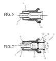
- the hooking means and locking of the socket and of the interface may consist of at least one claw provided on the sleeve and arranged to hang on said interface flange, said collar may also have means for blocking the rotation of said socket, such as at least one notch.
- the means for hooking and locking the socket and interface may consist of a screw system provided on the one hand on the socket and on the other hand on the interface collar.
- the sleeve may have on its outer surface relief shapes.
- the rear part of the interface can have a shape adapted to the member on which it is reported.
- connection device 1 is used to connect a tube 2 made for example of rigid or semi-rigid material. such as steel, aluminum or polyamide, at an interface 3 produced for example in a rigid material. It includes a swivel socket 4, placed so coaxial on tube 2 and interface 3.
- the socket 4 is produced for example in semi-rigid material and has an inner cylindrical part 5 terminated at one end by a perpendicular rim 6 whose diameter is greater than the diameter of the tube 2, this rim constituting a means for retaining said tube 2 as will be described below.
- the other end of the socket 4 is finished by two fixing lugs 7, at least one of which has the shape of a claw 8, these lugs constituting means for hooking and locking the interface 3 as this will be described below.
- the cylindrical part 5 is ends with a chamfer 5a.
- the socket 4 also has bosses 9 on its outer surface to improve its grip.
- the socket 4 is designed to be mounted on a specific tube 2 such as that shown in Figure 3.
- This tube 2 has a flared end region 10 obtained by means of a shoulder 11, said shoulder 11 being intended to be in abutment against the rim 6 of the sleeve 4 and constitute a retaining means.
- the flared end zone 10 can be replaced by a simple extended shoulder by an end zone then taking the same diameter as the tube 2 or in another suitable form.
- the end zone 10 shown is straight but may also have an increasing diameter.
- Tube 2 presents at its end receiving the interface 3, that is to say at the end of the flared area 10, a chamfer 12 complementary to chamfer 5a of bush 4.
- the internal length L of the cylindrical part 5 of the sleeve 4 is substantially greater than the distance d between the shoulder 11 and the end of the receiving tube the interface and the inside diameter of the socket 4 is in every point greater than the outside diameter of the tube 2.
- the interface 3 used for the device connection 1 has at the front a male end piece 13, of cylindrical shape, and equipped at least one peripheral sealing member 14 of the O-ring type or any other equivalent sealing member.
- the joint (s) seal 14 can be lubricated and interface 3 can be fitted with a plug protective seal (s) which will be removed at the last moment before connection.
- the male end piece 13 is of length 1 less than the distance d between the shoulder 11 and the end of the tube 2 receiving the interface and has a cylindrical shape of diameter slightly lower than that of said tube.
- the male end piece 13 is then extended by a attachment and indexing collar 15 itself extended by the rear part 16 of the interface 3.
- This rear part 16 ensures the connection of the interface 3 with another tube or any other organ. It is therefore of variable shape and size depending on the element to which it should be attached, for example, another semi-rigid tube 17a ( Figure 4a), or a rubber hose 17b ( Figure 4b). It is also possible to report interface 3 by gluing, welding or mounting or in any other way, force on the organ to receive the latter, so as to ensure a connection waterproof.
- the flange 15 is of general shape circular and has notches 18 which form stops for the tabs of fixing 7 and the claw 8 of the sleeve 4, said claw 8 trapping the collar 15.
- Said notches 18 constitute means for blocking the sleeve 4 in rotation. A positioning, a hooking and a locking of said socket are thus obtained. 4 on interface 3.
- the male end piece 13 At its end linked to the collar 15, the male end piece 13 has a chamfer 19 complementary to the chamfer 12 of the tube 2 (cf. Fig. 4a) to ensure immobilization by wedging the end of the tube 2 between the male end piece 13 of the interface 3 and the socket 4.
- connection device 1 is implemented from the as follows:
- the socket 4 is placed on the tube 2 and brought back to the height of the zone flared end 10.
- the tube 2 / swivel sleeve 4 assembly is placed on the male end piece 13 of the interface 3 fitted with its seal 14, the chamfer 12 of the tube 2 allowing mounting of the tube 2 on the interface 3 without damaging the seal 14. Due to the choice of the length I with respect to the distance d defined above, the end zone flared 10 of the tube 2 completely covers the male end piece 13 of the interface 3 in compressing its seal 14. The chamfer 12 of the tube 2 comes opposite the chamfer 19 of end piece 13.
- the rim 6 of the sleeve 4 is brought into abutment against the shoulder 11 of the tube 2 of so as to block it in translation. Because of the choice of the length L compared to the distance d defined above, the cylindrical part 5 completely covers the flared end region 10 of the tube 2 as shown in FIG. 2. The chamfer 5a of bush 4 comes opposite chamfer 12 of tube 2.
- the hooking claw 8 and the fixing lug 7 must be placed in look of the notches 18 provided on the collar 15 of the interface 3.
- the socket 4 is then pivoted until the fixing lugs 7 and the claw come into abutment hooking 8 against the notches 18, the claw 8 being forcibly clipped onto the flange 15.
- the connection device 1 is fully locked, which is obtained by turning the socket 4 only a quarter turn, which is very fast.
- the shapes in contact between the socket 4, the tube 2 and the male end piece 13 are cylindrical and define large overlap surfaces, on a length greater than at least once the diameter of the tube. Likewise, the diameters correspondents of these three parts are complementary to ensure mounting tight. All of these characteristics make it possible to maintain an effort of sufficient compression on the external surface of the tube 2 under which the member is located seal 14 and guarantee a good level of tightness as well as a connection mechanically resistant and reliable over time.
- the sleeve 4 can also provide stressing said tube 2 in its flared end region 10 in order to maintain a force necessary for the correct compression of the seal 14, avoiding thus the creep of the latter.
- connection device 1 To disconnect connection device 1, the reverse movement must be given to the swivel sleeve 4 in order to release the hooking claw 8 and the tab of fixing 7 of the collar 15 of the interface 3, ie a rotation over a quarter of a turn.
- the swivel sleeve 4 can be removed from interface 3 as well as tube 2. A new connection can then be made.
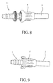
- the means for hooking and locking the socket 4 and the interface 3 can be constituted by other means than those described above, for example, a screw system ( Figure 8) or even a single or multiple claw system ( Figure 9), requiring or not a tool for disassembly.
- a screw system Figure 8
- Figure 9 a single or multiple claw system
- Many other solutions technological solutions can be envisaged to ensure indexing and locking of the socket on the interface. The choice will be made according to the field of application and the component development process (plastic injection, machining or other).
Landscapes
- Engineering & Computer Science (AREA)
- General Engineering & Computer Science (AREA)
- Mechanical Engineering (AREA)
- Quick-Acting Or Multi-Walled Pipe Joints (AREA)
- Mutual Connection Of Rods And Tubes (AREA)
Applications Claiming Priority (2)
| Application Number | Priority Date | Filing Date | Title |
|---|---|---|---|
| FR9815785 | 1998-12-10 | ||
| FR9815785A FR2787171B1 (fr) | 1998-12-10 | 1998-12-10 | Dispositif de raccordement demontable pour le raccordement d'un tube rigide ou semi-rigide et d'une interface rigide |
Publications (2)
| Publication Number | Publication Date |
|---|---|
| EP1008796A2 true EP1008796A2 (de) | 2000-06-14 |
| EP1008796A3 EP1008796A3 (de) | 2001-09-12 |
Family
ID=9533963
Family Applications (1)
| Application Number | Title | Priority Date | Filing Date |
|---|---|---|---|
| EP99440355A Withdrawn EP1008796A3 (de) | 1998-12-10 | 1999-12-10 | Verbindungsvorrichtung für die lösbare Verbindung eines Rohres an einem Endstück mittels einer koaxialen Hülse |
Country Status (2)
| Country | Link |
|---|---|
| EP (1) | EP1008796A3 (de) |
| FR (1) | FR2787171B1 (de) |
Cited By (4)
| Publication number | Priority date | Publication date | Assignee | Title |
|---|---|---|---|---|
| FR2806780A1 (fr) * | 2000-03-23 | 2001-09-28 | Legris Sa | Dispositif coulissant de raccordement de l'extremite d'un tube a un embout |
| CN108867603A (zh) * | 2018-06-21 | 2018-11-23 | 招商局重工(江苏)有限公司 | 一种圆柱型桩腿自升式平台冲桩接口 |
| CN110366717A (zh) * | 2017-02-22 | 2019-10-22 | 微软技术许可有限责任公司 | 感测尖端驻留 |
| US11054074B2 (en) * | 2016-09-21 | 2021-07-06 | Arnott, Llc | System and method for push-to-connect couplings with integrated filtration |
Citations (3)
| Publication number | Priority date | Publication date | Assignee | Title |
|---|---|---|---|---|
| FR1234795A (fr) | 1959-05-20 | 1960-10-19 | Bronzavia Sa | Raccord flexible pour tuyauteries rigides |
| CH400686A (de) | 1961-02-24 | 1965-10-15 | Heim Rudolf | Verbindungsstück für einen an einem Gehäuse anschliessbaren Schlauch |
| GB2086514A (en) | 1980-10-30 | 1982-05-12 | Gen Motors Corp | Quick-connect hydraulic coupling assemblies |
-
1998
- 1998-12-10 FR FR9815785A patent/FR2787171B1/fr not_active Expired - Fee Related
-
1999
- 1999-12-10 EP EP99440355A patent/EP1008796A3/de not_active Withdrawn
Patent Citations (3)
| Publication number | Priority date | Publication date | Assignee | Title |
|---|---|---|---|---|
| FR1234795A (fr) | 1959-05-20 | 1960-10-19 | Bronzavia Sa | Raccord flexible pour tuyauteries rigides |
| CH400686A (de) | 1961-02-24 | 1965-10-15 | Heim Rudolf | Verbindungsstück für einen an einem Gehäuse anschliessbaren Schlauch |
| GB2086514A (en) | 1980-10-30 | 1982-05-12 | Gen Motors Corp | Quick-connect hydraulic coupling assemblies |
Cited By (5)
| Publication number | Priority date | Publication date | Assignee | Title |
|---|---|---|---|---|
| FR2806780A1 (fr) * | 2000-03-23 | 2001-09-28 | Legris Sa | Dispositif coulissant de raccordement de l'extremite d'un tube a un embout |
| US11054074B2 (en) * | 2016-09-21 | 2021-07-06 | Arnott, Llc | System and method for push-to-connect couplings with integrated filtration |
| CN110366717A (zh) * | 2017-02-22 | 2019-10-22 | 微软技术许可有限责任公司 | 感测尖端驻留 |
| CN110366717B (zh) * | 2017-02-22 | 2023-01-10 | 微软技术许可有限责任公司 | 感测尖端驻留 |
| CN108867603A (zh) * | 2018-06-21 | 2018-11-23 | 招商局重工(江苏)有限公司 | 一种圆柱型桩腿自升式平台冲桩接口 |
Also Published As
| Publication number | Publication date |
|---|---|
| FR2787171A1 (fr) | 2000-06-16 |
| EP1008796A3 (de) | 2001-09-12 |
| FR2787171B1 (fr) | 2001-01-12 |
Similar Documents
| Publication | Publication Date | Title |
|---|---|---|
| EP1064489B1 (de) | Steck-kupplung für rohre | |
| FR2845149A1 (fr) | Dispositif et structure anti-rotation pour tuyau et raccord | |
| FR2718822A1 (fr) | Accouplement emboîtable à désaccouplement simplifié, pour relier deux conduits de circulation d'un fluide. | |
| EP0547942B1 (de) | Schnellverbindungseinrichtung zur dichten Verbindung zweier Leitungen oder zweier starrer oder halbstarrer Rohre | |
| EP0753697A1 (de) | Vorrichtung zur Schnellverbindung einer Rohrleitung mit einem Anschlussstück, insbesondere für einen Wärmetauscher, sowie ein mit dieser Vorrichtung bestückter Wärmetauscher | |
| FR2942650A1 (fr) | Dispositif de couplage de connexion rapide | |
| EP0621432B1 (de) | Vorrichtung zum dichten Verbinden eines Schlauches mit einem starren Rohrende | |
| EP0441683A1 (de) | Abgedichtete Verbindung für fluidführende Rohrleitungen | |
| FR2851634A1 (fr) | Pince de raccord et structure de raccordement de raccord destinees a verifier le raccordement complet entre un raccord et un tuyau | |
| FR3064713A1 (fr) | Procede de fabrication d'un agencement fluidique et agencement fluidique associe | |
| EP1258666B9 (de) | Schnellkupplung mit Befestigung durch elastischen, äusseren Ring | |
| EP3640516A1 (de) | Schnellkupplungsvorrichtung | |
| FR2679313A1 (fr) | Dispositif de serrage etanche pour le serrage d'un tube flexible monte a force a l'interieur d'un raccord tubulaire. | |
| EP1056969B1 (de) | Rastverbindung für eine rohrleitung | |
| FR2629891A1 (fr) | Raccord d'assemblage de canalisations notamment pour gaz | |
| EP1413815B1 (de) | Kupplung für zwei Rohre mit aufgeweiteten Enden | |
| EP1008796A2 (de) | Verbindungsvorrichtung für die lösbare Verbindung eines Rohres an einem Endstück mittels einer koaxialen Hülse | |
| EP0571286A1 (de) | Vorrichtung zum schnellen Verbinden von entweder einem rohrförmigen Element mit einem Rohrende oder einem System von rohrförmigen Elementen mit Rohrenden | |
| FR2688290A1 (fr) | Dispositif de jonction entre un accord tubulaire souple et un embout tubulaire rigide, notamment pour un circuit de refroidissement d'un vehicule automobile. | |
| EP0480818B1 (de) | Verbesserte Vorrichtung zum Verbinden eines Schlauchendes mit dem Ende eines starren Rohres | |
| FR2772875A1 (fr) | Dispositif de raccordement d'un tuyau souple a une paroi, en particulier d'un echangeur de chaleur de vehicule automobile | |
| FR2602572A1 (fr) | Dispositif de raccordement d'un tuyau souple autour d'un embout tubulaire rigide | |
| EP0481872B1 (de) | Anschlussvorrichtung zum Verbinden von zwei Rohren auf beiden Seiten eines Wandelementes | |
| EP3867557B1 (de) | Anordnung mit einer rohrleitung und einer verbindungsvorrichtung zum verbinden eines rohres mit einer wand der rohrleitung | |
| EP0327443A1 (de) | Verbindung zwischen einem Wärmetauscher und einem Rohrende |
Legal Events
| Date | Code | Title | Description |
|---|---|---|---|
| PUAI | Public reference made under article 153(3) epc to a published international application that has entered the european phase |
Free format text: ORIGINAL CODE: 0009012 |
|
| AK | Designated contracting states |
Kind code of ref document: A2 Designated state(s): AT BE CH CY DE DK ES FI FR GB GR IE IT LI LU MC NL PT SE |
|
| AX | Request for extension of the european patent |
Free format text: AL;LT;LV;MK;RO;SI |
|
| PUAL | Search report despatched |
Free format text: ORIGINAL CODE: 0009013 |
|
| AK | Designated contracting states |
Kind code of ref document: A3 Designated state(s): AT BE CH CY DE DK ES FI FR GB GR IE IT LI LU MC NL PT SE |
|
| AX | Request for extension of the european patent |
Free format text: AL;LT;LV;MK;RO;SI |
|
| AKX | Designation fees paid | ||
| REG | Reference to a national code |
Ref country code: DE Ref legal event code: 8566 |
|
| STAA | Information on the status of an ep patent application or granted ep patent |
Free format text: STATUS: THE APPLICATION IS DEEMED TO BE WITHDRAWN |
|
| 18D | Application deemed to be withdrawn |
Effective date: 20020313 |