EP1423636B1 - Vormontierte dichtungsverbindung - Google Patents
Vormontierte dichtungsverbindung Download PDFInfo
- Publication number
- EP1423636B1 EP1423636B1 EP02798756A EP02798756A EP1423636B1 EP 1423636 B1 EP1423636 B1 EP 1423636B1 EP 02798756 A EP02798756 A EP 02798756A EP 02798756 A EP02798756 A EP 02798756A EP 1423636 B1 EP1423636 B1 EP 1423636B1
- Authority
- EP
- European Patent Office
- Prior art keywords
- tube
- coupling
- fastener device
- presents
- coupling according
- Prior art date
- Legal status (The legal status is an assumption and is not a legal conclusion. Google has not performed a legal analysis and makes no representation as to the accuracy of the status listed.)
- Revoked
Links
Images

Classifications
-
- F—MECHANICAL ENGINEERING; LIGHTING; HEATING; WEAPONS; BLASTING
- F16—ENGINEERING ELEMENTS AND UNITS; GENERAL MEASURES FOR PRODUCING AND MAINTAINING EFFECTIVE FUNCTIONING OF MACHINES OR INSTALLATIONS; THERMAL INSULATION IN GENERAL
- F16L—PIPES; JOINTS OR FITTINGS FOR PIPES; SUPPORTS FOR PIPES, CABLES OR PROTECTIVE TUBING; MEANS FOR THERMAL INSULATION IN GENERAL
- F16L37/00—Couplings of the quick-acting type
- F16L37/08—Couplings of the quick-acting type in which the connection between abutting or axially overlapping ends is maintained by locking members
- F16L37/084—Couplings of the quick-acting type in which the connection between abutting or axially overlapping ends is maintained by locking members combined with automatic locking
- F16L37/098—Couplings of the quick-acting type in which the connection between abutting or axially overlapping ends is maintained by locking members combined with automatic locking by means of flexible hooks
- F16L37/0985—Couplings of the quick-acting type in which the connection between abutting or axially overlapping ends is maintained by locking members combined with automatic locking by means of flexible hooks the flexible hook extending radially inwardly from an outer part and engaging a bead, recess or the like on an inner part
Definitions
- the present invention relates to a pre-assembled connection for sealingly connecting a fluid transport tube and a nozzle.
- Such connectors are already known, for example US Pat. No. 4,844,512, US Pat. No. 5,328,216 or US Pat. No. 4,991,882. They comprise a female part that can be snapped into a male part constituting the end piece.
- the tube is fitted in a rear cylindrical region (fir tip) provided with ribs, the female part.
- the female portion also has two seal surfaces for receiving one or two seals with the tip.
- Such a coupling is relatively expensive, and moreover it imposes two levels of sealing achieved by different means, on the one hand at the rear between the tube and said rear cylindrical region, and in the front between the female parts and male.
- the quick couplings for tubes currently used also require two sealing times between the tube and the quick coupling, and between the quick coupling and the nozzle, as in the case of the two Patents cited above.
- these quick connectors have a high cost.
- Such connections are produced by NORMA, RAYMOND, LEGRIS, JOHN GUEST, ITT, etc.
- the invention aims to simplify the connection while improving functionality and in particular to implement a single element ensuring tightness, thereby reducing the risk of leakage.
- the invention thus relates to a preassembled coupling for sealingly connecting a fluid transport tube and a nozzle provided with at least one fastening element according to claim 1.
- the hooking device may have at least one gripping member exerting a lever effect on a hooking element to allow disassembly of the connector of the tip.
- the attachment device may have a cylindrical region sliding along the tube.
- At least one fastening element may be constituted by a snap arm.
- the attachment device advantageously has a rear end face for the sealing element.
- This face is for example flat, but it may be concave, the sealing element then having a convex face complementary to this concave face.
- At least one said snap arm and / or at least one gripping member can be connected to an annular ring.
- the invention also relates to a tight connection between a transport tube and a nozzle, which is characterized by the implementation of a coupling as defined above, assembled with the nozzle by cooperation of the fastening elements of the device hanging and the tip.
- the sealing element can be immobilized while being abutted between the annular bulge of the tube and the attachment device.
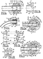
- the invention uses a quick coupling pre-assembled on a rigid or semi-rigid tube (that is to say rigid enough to ensure a seal), for example metal or plastic, which is put in place. form at its end before 42 to form an annular bead 41.
- This shaping can be done cold, or hot.
- a sealing element 5 made of elastomer, for example made of rubber, threaded onto the tube 4 (or overmoulded on it) makes it possible to seal the tube 4 and the tip 3 by compression, thanks to a attachment device 6, for example made of metal or thermoplastic material which is threaded onto the tube 4 and which is connected to the tip 3 which can be of a conventional type, for example a tip commonly used by car manufacturers in the cooling circuits.
- the hooking device 6 may be threaded, in particular by force, or overmolded onto the tube 4.
- the fitting being pre-assembled the assembly is carried out in a single operation, for example by simple snapping.
- the pre-assembled coupling comprises a generally cylindrical elastomer sealing element 5, the diameter of the inner contour 56 of which is substantially equal to or slightly smaller than the diameter of the outer contour 43 of the tube 4, for allow it to slide along the tube 4.
- the element 5 has on its outer cylindrical face 57 and / or on its cylindrical inner contour 56 one or more annular beads 51 and / or 52.
- the tube 4 can be formed to allow clearance at 90 ° or at another angle.
- the element 5 may be overmoulded around the tube 4.
- the annular bead 41 at the front end of the tube 4 serves as a front stop at the front face 54 of the sealing element 5.
- the attachment device 6 has a cylindrical region 61 whose inner contour 69 has a diameter adapted to its sliding along the outer contour 43 of the tube 4.
- the attachment means 6 are for example constituted by snap arms 64 for example two arms located 180 ° from each other (as in Figure 2c).
- Each arm 64 has a ramp region 66 for a pawl 63, which snaps into a groove 34 of a cylindrical region 32 of the tip 3.
- These arms 64 are for example articulated from an annular ring 62
- a front face 65 of the ring 62 and / or of the region 61 serves as a rear stop on the rear face 55 of the sealing element 5.
- the ramp region 66 cooperates with a corresponding ramp region 33 of the nozzle 3 to facilitate the approach of the coupling 2 before snapping, which is performed in the position shown in FIG. 1 C. In this position, the inner face 67 of the arms 64 adjoins the ramp regions 33.
- the sealing element 5 then provides the two desired sealing functions, by its internal contour 56 between the tube 4 and the coupling 2 and by its external contour 57, between the coupling 2 and the end piece 3 provided with a base 31.
- a gripping pin 68 is associated with each arm 64 to allow its release of the groove 34 'by leverage, slightly deforming the annular ring 62.
- the pins 68 extend outwardly of the connector to facilitate grip.
- the annular ring 62 'and therefore its front face 65' is not flat, as in the previous embodiments, but it is concave and its front face 65 'cooperates with a complementary face convex of complementary profile 55 'of the sealing element 5.
- This rounded shape allows compression of the pins 68', easy disassembly of the connector 2 relative to the nozzle 3.
- the lugs 68 ' are arranged in the extension of the arms 64 and they have an end 68 "bent for example at 90 °, towards the region 61.
- the annular end 41 carries a flat part 45 angular keying. This can also be the case of the seal 5, with an end flat 58, opposite the flat part 45.
- the flat part 45 makes it possible to guarantee the orientation of the tube (in a rotation about its axis), unlike a fir tip which can rotate. This indexing may be independent of the orientation of the intermediate components.
- the attachment piece 6 may have a cylindrical ring 71 adjacent the front face 65 and which extends forward by two tabs 72 whose inner contour 75 is adapted to fit into the perimeter of the seal 5 downstream of its rear face 55.
- the front face 73 of the ring 71 is in abutment on the rear face 55 of the gasket 5.
- the gasket 5 is abutted by its front face 53 on the annular end 41 and the fitting of the inner contour 75 of the tabs 72 around the seal avoids a rotation of the part 6 around the tube 4.
- An angular indexing of the coupling components has thus been achieved. relative to the flat part 45, which is required in certain applications where the part 6 must be positioned in a precise angular position with respect to the flat part 45.
- this angular orientation can be obtained by force-fitting the part 6 onto the tube 4, possibly with the use of the indexing tabs 72.
- the angular indexing by the flat part 45 allows angularly identifying a clearance of the tube (at 90 ° or at another angle), for mounting the base. There is no need for this to change the elements that make up the fitting. In other words, there is only one type of fitting that allows all the angular clearances, contrary to Art. Anterior, where it is necessary to adapt the pieces of fittings.
- the invention makes it possible to make connections for fluid transport tubes (water, antifreeze, oil, fuel, air, refrigerant air conditioning circuit) more particularly in the automotive field.
- fluid transport tubes water, antifreeze, oil, fuel, air, refrigerant air conditioning circuit
- Another advantage of the invention is that only the tube 4 and the seal 5 must resist the fluid.
- the invention can be applied in particular to the degassing circuit of an automobile cooling circuit.
Claims (16)
- Vormontiertes Verbindungsstück zum in abdichtender Weise Verbinden eines Fluidtransportrohres und eines Ansatzstücks, welches mit wenigstens einem Kopplungselement mit einer Rille in einem zylindrischen Außenbereich versehen ist,
dadurch gekennzeichnet,
dass es umfasst:- ein besagtes Rohr (4), welches an einem Vorderende (42) eine ringförmige Verdickung (41) aufweist;- eine Kopplungsvorrichtung (6), welche auf das Rohr (4) aufgeschoben ist und wenigstens einen Arm (63, 64) aufweist, welcher ein Einrastelement bildet, das in einer Rille (34) eines zylindrischen Außenbereichs (32) des Ansatzstücks (3) einrastet;- ein zylindrisches Dichtungselement (5) aus einem Elastomer, welches um das Rohr (4) herum angeordnet ist und in der Kopplungsvorrichtung (6) und der ringförmigen Verdickung (41) aufgenommen ist, wobei das Dichtungselement (5) eine innere Oberfläche (56) zur Abdichtung mit einer äußeren Oberfläche (43) des Rohres (4) und eine äußere Oberfläche (57) zur Abdichtung mit einer inneren Oberfläche des Ansatzstücks (3) aufweist. - Verbindungsstück nach Anspruch 1,
dadurch gekennzeichnet,
dass die Kopplungsvorrichtung (6) wenigstens ein Greiforgan (68) aufweist, welches einen Hebeleffekt auf ein Kopplungselement (64, 66) ausübt, um zu ermöglichen, das Verbindungsstück (2) und das Ansatzstück (3) auseinander zu nehmen. - Verbindungsstück nach einem der Ansprüche 1 oder 2,
dadurch gekennzeichnet,
dass die Kopplungsvorrichtung (6) einen zylindrischen Bereich (61, 69) aufweist, welcher entlang des Rohres (4) verschiebbar ist. - Verbindungsstück nach einem der Ansprüche 1 oder 2,
dadurch gekennzeichnet,
dass die Kopplungsvorrichtung (6) einen zylindrischen Bereich (61, 69) aufweist, welcher mit Kraft entlang des Rohres (4) verschiebbar ist. - Verbindungsstück nach einem der vorhergehenden Ansprüche,
dadurch gekennzeichnet,
dass die Kopplungsvorrichtung (6) eine Seite (65, 65') aufweist, welche einen hinteren Anschlag (55, 55') für das Dichtungselement (5) bildet. - Verbindungsstück nach Anspruch 5,
dadurch gekennzeichnet,
dass die Seite (65) eben ist. - Verbindungsstück nach Anspruch 5,
dadurch gekennzeichnet,
dass die Seite (65') konkav ist und dass das Dichtungselement (5) eine konvexe Seite (55') aufweist, welche komplementär zu der konkaven Seite (65') ist. - Verbindungsstück nach einem der vorhergehenden Ansprüche,
dadurch gekennzeichnet,
dass wenigstens ein besagter Arm (63, 64) sich mit einem besagten ringförmigen Kranz (62) der Kopplungsvorrichtung (6) verbindet. - Verbindungsstück nach Anspruch 8,
dadurch gekennzeichnet,
dass wenigstens ein Greiforgan (68) sich mit dem ringförmigen Kranz (62) verbindet. - Verbindungsstück nach einem der vorhergehenden Ansprüche,
dadurch gekennzeichnet,
dass die ringförmige Verdickung (41) und/oder der Vorderteil der Dichtung (5) an ihrem/seinem Umfang ein Winkelpositionierungselement (45, 58), insbesondere eine Abflachung, aufweist. - Verbindungsstück nach einem der vorhergehenden Ansprüche,
dadurch gekennzeichnet,
dass die Kopplungsvorrichtung (6) wenigstens ein Element (72) aufweist, welches sich auf den Innendurchmesser des Hinterteils der Dichtung (5) aufpressen kann. - Verbindungsstück nach einem der vorhergehenden Ansprüche,
dadurch gekennzeichnet,
dass es vormontiert ist, wobei die Kopplungsvorrichtung (6) auf der Dichtung (5) und die Dichtung (5) auf der ringförmigen Verdickung (41) in Anschlag gebracht ist. - Verbindungsstück nach Anspruch 11 und 12,
dadurch gekennzeichnet,
dass die Kopplungsvorrichtung (6) vormontiert ist, wobei sie im Winkel bezüglich des Winkelpositionierungselements (45, 58) positioniert ist. - Abgedichtete Verbindung zwischen einem Transportrohr und einem Ansatzstück,
dadurch gekennzeichnet,
dass sie ein Verbindungsstück (2) gemäß einem der vorhergehenden Ansprüche umfasst, welches mit dem Ansatzstück (3) durch Zusammenwirken der Kopplungselemente (63, 34) der Kopplungsvorrichtung (6) und des Ansatzstücks (3) zusammengefügt ist. - Abgedichtete Verbindung nach Anspruch 14,
dadurch gekennzeichnet,
dass das Dichtungselement (5) fixiert ist, wobei es sich zwischen der ringförmigen Verdickung (41) des Rohres (4) und der Kopplungsvorrichtung (6) im Anschlag (53, 55) befindet. - Abgedichtete Verbindung nach Anspruch 15,
dadurch gekennzeichnet,
dass das Verbindungsstück wenigstens ein besagtes Winkelpositionierungselement (45, 58) aufweist und dass die Kopplungsvorrichtung (6) im Winkel bezüglich des Winkelpositionierungselements (45, 58) positioniert ist.
Applications Claiming Priority (3)
| Application Number | Priority Date | Filing Date | Title |
|---|---|---|---|
| FR0111405A FR2829219B1 (fr) | 2001-09-04 | 2001-09-04 | Raccord d'etancheite pre-assemble |
| FR0111405 | 2001-09-04 | ||
| PCT/FR2002/002997 WO2003025450A1 (fr) | 2001-09-04 | 2002-09-03 | Raccord d'etancheite pre-assemble |
Publications (2)
| Publication Number | Publication Date |
|---|---|
| EP1423636A1 EP1423636A1 (de) | 2004-06-02 |
| EP1423636B1 true EP1423636B1 (de) | 2006-01-11 |
Family
ID=8866933
Family Applications (1)
| Application Number | Title | Priority Date | Filing Date |
|---|---|---|---|
| EP02798756A Revoked EP1423636B1 (de) | 2001-09-04 | 2002-09-03 | Vormontierte dichtungsverbindung |
Country Status (10)
| Country | Link |
|---|---|
| US (1) | US20040232696A1 (de) |
| EP (1) | EP1423636B1 (de) |
| AT (1) | ATE315757T1 (de) |
| BR (1) | BR0212171A (de) |
| DE (1) | DE60208715T2 (de) |
| FR (1) | FR2829219B1 (de) |
| MX (1) | MXPA04002044A (de) |
| PL (1) | PL369430A1 (de) |
| PT (1) | PT1423636E (de) |
| WO (1) | WO2003025450A1 (de) |
Families Citing this family (62)
| Publication number | Priority date | Publication date | Assignee | Title |
|---|---|---|---|---|
| DE10250421A1 (de) * | 2002-10-30 | 2004-05-13 | A. Raymond & Cie | Verbindungselement |
| US20050082828A1 (en) | 2003-09-12 | 2005-04-21 | Wicks Jeffrey C. | Releasable connection assembly for joining tubing sections |
| US8636721B2 (en) | 2003-11-20 | 2014-01-28 | Henry M. Jackson Foundation For The Advancement Of Military Medicine, Inc. | Portable hand pump for evacuation of fluids |
| US8337475B2 (en) * | 2004-10-12 | 2012-12-25 | C. R. Bard, Inc. | Corporeal drainage system |
| US7448653B2 (en) | 2005-06-10 | 2008-11-11 | Value Plastics, Inc. | Female connector for releasable coupling with a male connector defining a fluid conduit |
| US7806139B2 (en) | 2006-01-20 | 2010-10-05 | Value Plastics, Inc. | Fluid conduit coupling assembly having male and female couplers with integral valves |
| DE102006011617A1 (de) * | 2006-03-14 | 2007-09-20 | Norma Germany Gmbh | Verbindungsanordnung zur Verbindung eines Rohrstutzens mit einem Schlauch |
| US20090058082A1 (en) * | 2007-09-05 | 2009-03-05 | Green Ronald D | Two-part quick connect retention attachment for flexible tubing in a water supply system |
| KR101188513B1 (ko) * | 2007-11-05 | 2012-10-05 | 엘지전자 주식회사 | 냉장고 |
| USD654573S1 (en) | 2007-11-19 | 2012-02-21 | Value Plastics, Inc. | Female quick connect fitting |
| DE202008000145U1 (de) * | 2008-01-02 | 2009-05-20 | Voss Automotive Gmbh | Verbindungssystem für fluidführende Systeme |
| DE102008015811A1 (de) * | 2008-03-27 | 2009-10-01 | Fte Automotive Gmbh | Lösbare Steckverbindung für Rohrleitungen od. dgl. |
| US8235426B2 (en) | 2008-07-03 | 2012-08-07 | Nordson Corporation | Latch assembly for joining two conduits |
| USD630320S1 (en) | 2008-07-03 | 2011-01-04 | Value Plastics, Inc. | Connector for fluid tubing |
| USD629894S1 (en) | 2008-07-03 | 2010-12-28 | Value Plastics, Inc. | Male body of connector for fluid tubing |
| USD634840S1 (en) | 2008-07-03 | 2011-03-22 | Value Plastics, Inc. | Female body of connector for fluid tubing |
| EP2158935B1 (de) * | 2008-08-29 | 2014-07-16 | Dräger Medical GmbH | Steckverbinder für medizinische Schläuche |
| DE102008061462B4 (de) * | 2008-12-10 | 2011-04-14 | Illinois Tool Works Inc., Glenview | Kühlsystem für einen Verbrennungsmotor |
| FR2939864B1 (fr) * | 2008-12-12 | 2010-12-03 | Cie Mediterraneenne Des Cafes | Connecteur, systeme et procede de raccordement de deux organes hydrauliques. |
| USD655393S1 (en) | 2009-06-23 | 2012-03-06 | Value Plastics, Inc. | Multi-port valve |
| US9388929B2 (en) | 2009-12-09 | 2016-07-12 | Nordson Corporation | Male bayonet connector |
| USD783815S1 (en) | 2009-12-09 | 2017-04-11 | General Electric Company | Male dual lumen bayonet connector |
| USD649240S1 (en) | 2009-12-09 | 2011-11-22 | Value Plastics, Inc. | Male dual lumen bayonet connector |
| US10711930B2 (en) | 2009-12-09 | 2020-07-14 | Nordson Corporation | Releasable connection assembly |
| JP5814257B2 (ja) | 2009-12-23 | 2015-11-17 | ノードソン コーポレーションNordson Corporation | 一体成形された片持ちばねを有するボタンラッチ |
| EP2516913B1 (de) | 2009-12-23 | 2014-09-17 | Nordson Corporation | Fluidverbinderverriegelungen mit profildurchführungen |
| US8469404B2 (en) * | 2010-08-23 | 2013-06-25 | Lg Chem, Ltd. | Connecting assembly |
| US8353315B2 (en) | 2010-08-23 | 2013-01-15 | Lg Chem, Ltd. | End cap |
| US8758922B2 (en) | 2010-08-23 | 2014-06-24 | Lg Chem, Ltd. | Battery system and manifold assembly with two manifold members removably coupled together |
| US8920956B2 (en) | 2010-08-23 | 2014-12-30 | Lg Chem, Ltd. | Battery system and manifold assembly having a manifold member and a connecting fitting |
| USD652511S1 (en) | 2011-02-11 | 2012-01-17 | Value Plastics, Inc. | Female body of connector for fluid tubing |
| USD652510S1 (en) | 2011-02-11 | 2012-01-17 | Value Plastics, Inc. | Connector for fluid tubing |
| USD663022S1 (en) | 2011-02-11 | 2012-07-03 | Nordson Corporation | Male body of connector for fluid tubing |
| USD699841S1 (en) | 2011-07-29 | 2014-02-18 | Nordson Corporation | Female body of connector for fluid tubing |
| USD698440S1 (en) | 2011-07-29 | 2014-01-28 | Nordson Corporation | Connector for fluid tubing |
| USD699840S1 (en) | 2011-07-29 | 2014-02-18 | Nordson Corporation | Male body of connector for fluid tubing |
| CN102506393B (zh) * | 2011-10-27 | 2014-05-14 | 深圳市华星光电技术有限公司 | 背光模组及其连接装置 |
| USD709612S1 (en) | 2011-12-23 | 2014-07-22 | Nordson Corporation | Female dual lumen connector |
| DE102012102191A1 (de) * | 2012-03-15 | 2013-09-19 | Voss Automotive Gmbh | "Steck-Verbindungssystem, insbesondere für fluidische Leitungen, Armaturen oder Aggregate" |
| JP2012139554A (ja) * | 2012-04-26 | 2012-07-26 | Jms Co Ltd | 連通用ロックコネクタ |
| DE102012104288A1 (de) * | 2012-05-16 | 2013-11-21 | Voss Automotive Gmbh | "Steckverbindung für Fluid-Leitungen und Halteteil für eine derartige Steckverbindung" |
| US8974934B2 (en) | 2012-08-16 | 2015-03-10 | Lg Chem, Ltd. | Battery module |
| WO2014070877A1 (en) * | 2012-11-02 | 2014-05-08 | Advanced Technology Materials, Inc. | Dip tube assemblies and methods of manufacturing the same |
| CN103225723A (zh) * | 2013-03-26 | 2013-07-31 | 安徽省华久管业有限公司 | 一种新型塑料管接头 |
| DE102013208548A1 (de) * | 2013-05-08 | 2014-11-13 | Labomatic Instruments Ag | Verbindungssystem und Verfahren zum Verbinden von fluidführenden Bauteilen |
| JP6250982B2 (ja) * | 2013-08-27 | 2017-12-20 | ニプロ株式会社 | コネクタ接続用ロック部材 |
| CN104019308A (zh) * | 2014-06-26 | 2014-09-03 | 李婧 | 一种热水管接头 |
| GB2549713A (en) * | 2016-04-25 | 2017-11-01 | Perkins Engines Co Ltd | Leak off clip for fuel injectors |
| AU2017299466B2 (en) | 2016-07-18 | 2022-07-14 | Merit Medical Systems, Inc. | Inflatable radial artery compression device |
| USD838366S1 (en) | 2016-10-31 | 2019-01-15 | Nordson Corporation | Blood pressure connector |
| SI3354955T1 (sl) * | 2017-01-30 | 2023-07-31 | Georg Fischer Harvel Llc | Cevna spojka in postopek spajanja |
| DE102017002395B4 (de) * | 2017-03-14 | 2024-03-21 | Stiebel Eltron Gmbh & Co. Kg | Anschlussstutzen zum Anschluss an ein Haustechnikgerät und Verfahren zur Montage eines Anschlussstutzens |
| US10781958B2 (en) | 2017-10-31 | 2020-09-22 | Oetiker Ny, Inc. | Low peak insertion tube end form |
| JP6493705B2 (ja) * | 2017-11-24 | 2019-04-03 | ニプロ株式会社 | コネクタ接続用ロック部材 |
| JP7174945B2 (ja) * | 2018-05-18 | 2022-11-18 | 株式会社ジェイ・エム・エス | 留置針装置 |
| DE112019002531T5 (de) * | 2018-05-18 | 2021-02-18 | Hiroshima University | Verweilkanülenvorrichtung |
| DE102018008709A1 (de) * | 2018-11-06 | 2020-05-07 | Ferdinand Müller-Niksic | Schnellsteckverschluss |
| DE102019112239A1 (de) * | 2019-05-10 | 2020-11-12 | Mahle International Gmbh | Wärmeübertrager |
| FR3102528B1 (fr) * | 2019-10-28 | 2021-10-15 | Sogefi Filtration Spa | Dispositif de raccordement de conduit |
| DE102020104170A1 (de) * | 2020-02-18 | 2021-08-19 | Bayerische Motoren Werke Aktiengesellschaft | Anschlusseinrichtung für einen Getriebeentlüfter |
| US11293576B2 (en) * | 2020-08-31 | 2022-04-05 | Caremed Supply Inc. | Gas supply connector |
| WO2024056119A1 (de) * | 2022-09-14 | 2024-03-21 | Schaeffler Technologies AG & Co. KG | Gehäuseanordnung mit einem an einem wandelement montierten druckadapter; sowie antriebsvorrichtung |
Family Cites Families (14)
| Publication number | Priority date | Publication date | Assignee | Title |
|---|---|---|---|---|
| DE3444817A1 (de) * | 1984-01-20 | 1985-07-25 | Rasmussen Gmbh, 6457 Maintal | Steckkupplung |
| JPS6150888U (de) * | 1984-09-07 | 1986-04-05 | ||
| FR2617943B1 (fr) | 1987-07-06 | 1990-10-05 | Inventa Ag | Raccord rapide destine a relier une conduite flexible ou rigide |
| JPH0674875B2 (ja) | 1988-12-07 | 1994-09-21 | エムス − インヴエンタ・アクチエンゲゼルシヤフト | 迅速断ち継ぎ継手 |
| US5123677A (en) * | 1990-05-31 | 1992-06-23 | Swagelok-Quick Connect Co. | All plastic quick-connect coupling |
| IT220447Z2 (it) * | 1990-06-08 | 1993-09-22 | Italiana Serrature Torino | Gruppo di collegamento per circuiti di circolazione del liquido di raffreddamento del motore di un veicolo |
| FR2665507B1 (fr) * | 1990-07-31 | 1992-11-27 | Hutchinson Sa | Dispositif pour l'assemblage rapide d'une durite a un echangeur de chaleur d'un vehicule automobile. |
| JP3104929B2 (ja) * | 1992-03-11 | 2000-10-30 | 臼井国際産業株式会社 | 細径配管接続継手 |
| JP3148857B2 (ja) * | 1997-11-10 | 2001-03-26 | 日本ピラー工業株式会社 | 樹脂製管継手 |
| US6155607A (en) * | 1998-02-17 | 2000-12-05 | Parker-Hannifin Corporation | Quick connect coupling |
| US6199919B1 (en) * | 1998-03-31 | 2001-03-13 | Tokai Rubber Industries, Ltd. | Tube connecting structure |
| US6481759B1 (en) * | 1999-03-31 | 2002-11-19 | Tokai Rubber Industries, Ltd. | Connecting structure |
| US6173994B1 (en) * | 1999-08-20 | 2001-01-16 | Ti Group Automotive Systems Corp. | Coupling assemblies for providing fluid connection |
| JP3452196B2 (ja) * | 2000-08-31 | 2003-09-29 | 株式会社フロウエル | チューブ継手および、その施工方法 |
-
2001
- 2001-09-04 FR FR0111405A patent/FR2829219B1/fr not_active Expired - Lifetime
-
2002
- 2002-09-02 US US10/488,389 patent/US20040232696A1/en not_active Abandoned
- 2002-09-03 WO PCT/FR2002/002997 patent/WO2003025450A1/fr not_active Application Discontinuation
- 2002-09-03 PL PL02369430A patent/PL369430A1/xx unknown
- 2002-09-03 DE DE60208715T patent/DE60208715T2/de not_active Revoked
- 2002-09-03 MX MXPA04002044A patent/MXPA04002044A/es active IP Right Grant
- 2002-09-03 AT AT02798756T patent/ATE315757T1/de not_active IP Right Cessation
- 2002-09-03 EP EP02798756A patent/EP1423636B1/de not_active Revoked
- 2002-09-03 BR BR0212171-9A patent/BR0212171A/pt active Search and Examination
- 2002-09-03 PT PT02798756T patent/PT1423636E/pt unknown
Also Published As
| Publication number | Publication date |
|---|---|
| WO2003025450A1 (fr) | 2003-03-27 |
| US20040232696A1 (en) | 2004-11-25 |
| FR2829219A1 (fr) | 2003-03-07 |
| FR2829219B1 (fr) | 2004-12-17 |
| DE60208715T2 (de) | 2006-08-24 |
| PL369430A1 (en) | 2005-04-18 |
| EP1423636A1 (de) | 2004-06-02 |
| ATE315757T1 (de) | 2006-02-15 |
| BR0212171A (pt) | 2004-07-20 |
| MXPA04002044A (es) | 2004-06-07 |
| PT1423636E (pt) | 2006-05-31 |
| DE60208715D1 (de) | 2006-04-06 |
Similar Documents
| Publication | Publication Date | Title |
|---|---|---|
| EP1423636B1 (de) | Vormontierte dichtungsverbindung | |
| EP1064489B1 (de) | Steck-kupplung für rohre | |
| EP0840867B1 (de) | Vorrichtung zum dichten verbinden eines starren rohrendstückes mit einem schlauch und herstellungsverfahren für eine solche vorrichtung | |
| EP3014159B1 (de) | Fluidstecker mit klemme und schutz | |
| EP0360634B1 (de) | Verbindungseinrichtung zwischen einem Schlauchverbindungsstück und dem starren Rohrende eines Druckmittelkreislaufs | |
| EP0753697A1 (de) | Vorrichtung zur Schnellverbindung einer Rohrleitung mit einem Anschlussstück, insbesondere für einen Wärmetauscher, sowie ein mit dieser Vorrichtung bestückter Wärmetauscher | |
| EP1493958B1 (de) | Ringförmige Dichtung für Fluidtransferkupplung und Kupplung mit einer solchen Dichtung | |
| FR2738893A1 (fr) | Procede de realisation d'un embout, embout et connecteur realises par ce procede et circuit comportant un tel connecteur | |
| EP3036463B1 (de) | Wulstdichtung und verbindungsvorrichtung mit solch einer dichtung | |
| EP1941201B1 (de) | Verbindungsvorrichtung mit geschweisstem körper | |
| FR3064713A1 (fr) | Procede de fabrication d'un agencement fluidique et agencement fluidique associe | |
| WO2000079172A1 (fr) | Dispositif de raccord etanche pour conduit de fluide, en particulier pour vehicule automobile | |
| EP1533558B1 (de) | Koaxiale Rohrverbindung | |
| EP1056969A1 (de) | Rastverbindung für eine rohrleitung | |
| EP2369213B1 (de) | Rastverbindbare schlauchschnellkupplung und schlauchkupplungsmethode | |
| EP0338880B1 (de) | Verbindungseinrichtung zwischen einem schlauchartigen Verbindungsteil und einem starren Rohrende für einen Druckmittelkreislauf | |
| WO2000050798A1 (fr) | Dispositif d'etancheite et raccord equipe d'un tel dispositif | |
| FR2787171A1 (fr) | Dispositif de raccordement demontable pour le raccordement d'un tube rigide ou semi-rigide et d'une interface rigide | |
| FR2628819A1 (fr) | Dispositif de jonction entre un raccord tubulaire souple et un embout tubulaire rigide | |
| EP3215779A1 (de) | Vorrichtung zur befestigung eines starren steckerendstücks an einem flexiblen aufnahmerohr und herstellungsverfahren dafür | |
| EP0327443A1 (de) | Verbindung zwischen einem Wärmetauscher und einem Rohrende | |
| FR2927978A1 (fr) | Organe de conformation d'une portion d'extremite de conduite rectiligne et ensemble de raccordement comportant un tel organe | |
| FR2962187A1 (fr) | Dispositif et procede de raccordement en particulier pour circuit de refroidissement d'eau de vehicule automobile. | |
| FR3098880A1 (fr) | Raccord fluidique pour transfert de fluide. | |
| FR3107582A1 (fr) | Raccord rapide de tuyaux avec anneau en elastomere donnant une flexibilite |
Legal Events
| Date | Code | Title | Description |
|---|---|---|---|
| PUAI | Public reference made under article 153(3) epc to a published international application that has entered the european phase |
Free format text: ORIGINAL CODE: 0009012 |
|
| 17P | Request for examination filed |
Effective date: 20040220 |
|
| AK | Designated contracting states |
Kind code of ref document: A1 Designated state(s): AT BE BG CH CY CZ DE DK EE ES FI FR GB GR IE IT LI LU MC NL PT SE SK TR |
|
| AX | Request for extension of the european patent |
Extension state: AL LT LV MK RO SI |
|
| 17Q | First examination report despatched |
Effective date: 20050221 |
|
| GRAP | Despatch of communication of intention to grant a patent |
Free format text: ORIGINAL CODE: EPIDOSNIGR1 |
|
| GRAS | Grant fee paid |
Free format text: ORIGINAL CODE: EPIDOSNIGR3 |
|
| GRAA | (expected) grant |
Free format text: ORIGINAL CODE: 0009210 |
|
| AK | Designated contracting states |
Kind code of ref document: B1 Designated state(s): AT BE BG CH CY CZ DE DK EE ES FI FR GB GR IE IT LI LU MC NL PT SE SK TR |
|
| PG25 | Lapsed in a contracting state [announced via postgrant information from national office to epo] |
Ref country code: IT Free format text: LAPSE BECAUSE OF FAILURE TO SUBMIT A TRANSLATION OF THE DESCRIPTION OR TO PAY THE FEE WITHIN THE PRESCRIBED TIME-LIMIT;WARNING: LAPSES OF ITALIAN PATENTS WITH EFFECTIVE DATE BEFORE 2007 MAY HAVE OCCURRED AT ANY TIME BEFORE 2007. THE CORRECT EFFECTIVE DATE MAY BE DIFFERENT FROM THE ONE RECORDED. Effective date: 20060111 Ref country code: NL Free format text: LAPSE BECAUSE OF FAILURE TO SUBMIT A TRANSLATION OF THE DESCRIPTION OR TO PAY THE FEE WITHIN THE PRESCRIBED TIME-LIMIT Effective date: 20060111 Ref country code: FI Free format text: LAPSE BECAUSE OF FAILURE TO SUBMIT A TRANSLATION OF THE DESCRIPTION OR TO PAY THE FEE WITHIN THE PRESCRIBED TIME-LIMIT Effective date: 20060111 Ref country code: IE Free format text: LAPSE BECAUSE OF FAILURE TO SUBMIT A TRANSLATION OF THE DESCRIPTION OR TO PAY THE FEE WITHIN THE PRESCRIBED TIME-LIMIT Effective date: 20060111 Ref country code: GB Free format text: LAPSE BECAUSE OF FAILURE TO SUBMIT A TRANSLATION OF THE DESCRIPTION OR TO PAY THE FEE WITHIN THE PRESCRIBED TIME-LIMIT Effective date: 20060111 Ref country code: AT Free format text: LAPSE BECAUSE OF FAILURE TO SUBMIT A TRANSLATION OF THE DESCRIPTION OR TO PAY THE FEE WITHIN THE PRESCRIBED TIME-LIMIT Effective date: 20060111 |
|
| REG | Reference to a national code |
Ref country code: CH Ref legal event code: EP |
|
| REG | Reference to a national code |
Ref country code: IE Ref legal event code: FG4D Free format text: LANGUAGE OF EP DOCUMENT: FRENCH |
|
| REF | Corresponds to: |
Ref document number: 60208715 Country of ref document: DE Date of ref document: 20060406 Kind code of ref document: P |
|
| PG25 | Lapsed in a contracting state [announced via postgrant information from national office to epo] |
Ref country code: DK Free format text: LAPSE BECAUSE OF FAILURE TO SUBMIT A TRANSLATION OF THE DESCRIPTION OR TO PAY THE FEE WITHIN THE PRESCRIBED TIME-LIMIT Effective date: 20060411 Ref country code: SE Free format text: LAPSE BECAUSE OF FAILURE TO SUBMIT A TRANSLATION OF THE DESCRIPTION OR TO PAY THE FEE WITHIN THE PRESCRIBED TIME-LIMIT Effective date: 20060411 |
|
| PG25 | Lapsed in a contracting state [announced via postgrant information from national office to epo] |
Ref country code: ES Free format text: LAPSE BECAUSE OF FAILURE TO SUBMIT A TRANSLATION OF THE DESCRIPTION OR TO PAY THE FEE WITHIN THE PRESCRIBED TIME-LIMIT Effective date: 20060422 |
|
| REG | Reference to a national code |
Ref country code: PT Ref legal event code: SC4A Effective date: 20060404 |
|
| NLV1 | Nl: lapsed or annulled due to failure to fulfill the requirements of art. 29p and 29m of the patents act | ||
| PGFP | Annual fee paid to national office [announced via postgrant information from national office to epo] |
Ref country code: FR Payment date: 20060728 Year of fee payment: 5 |
|
| GBV | Gb: ep patent (uk) treated as always having been void in accordance with gb section 77(7)/1977 [no translation filed] |
Effective date: 20060111 |
|
| REG | Reference to a national code |
Ref country code: IE Ref legal event code: FD4D |
|
| PGFP | Annual fee paid to national office [announced via postgrant information from national office to epo] |
Ref country code: TR Payment date: 20060829 Year of fee payment: 5 |
|
| PGFP | Annual fee paid to national office [announced via postgrant information from national office to epo] |
Ref country code: PT Payment date: 20060831 Year of fee payment: 5 |
|
| PGFP | Annual fee paid to national office [announced via postgrant information from national office to epo] |
Ref country code: SK Payment date: 20060904 Year of fee payment: 5 |
|
| PGFP | Annual fee paid to national office [announced via postgrant information from national office to epo] |
Ref country code: EE Payment date: 20060919 Year of fee payment: 5 |
|
| PGFP | Annual fee paid to national office [announced via postgrant information from national office to epo] |
Ref country code: DE Payment date: 20060926 Year of fee payment: 5 |
|
| PG25 | Lapsed in a contracting state [announced via postgrant information from national office to epo] |
Ref country code: BE Free format text: LAPSE BECAUSE OF NON-PAYMENT OF DUE FEES Effective date: 20060930 Ref country code: LI Free format text: LAPSE BECAUSE OF NON-PAYMENT OF DUE FEES Effective date: 20060930 Ref country code: MC Free format text: LAPSE BECAUSE OF NON-PAYMENT OF DUE FEES Effective date: 20060930 Ref country code: CH Free format text: LAPSE BECAUSE OF NON-PAYMENT OF DUE FEES Effective date: 20060930 |
|
| PLBI | Opposition filed |
Free format text: ORIGINAL CODE: 0009260 |
|
| 26 | Opposition filed |
Opponent name: VERITAS AG Effective date: 20060927 |
|
| PLAX | Notice of opposition and request to file observation + time limit sent |
Free format text: ORIGINAL CODE: EPIDOSNOBS2 |
|
| REG | Reference to a national code |
Ref country code: CH Ref legal event code: PL |
|
| BERE | Be: lapsed |
Owner name: HUTCHINSON Effective date: 20060930 |
|
| PG25 | Lapsed in a contracting state [announced via postgrant information from national office to epo] |
Ref country code: GR Free format text: LAPSE BECAUSE OF FAILURE TO SUBMIT A TRANSLATION OF THE DESCRIPTION OR TO PAY THE FEE WITHIN THE PRESCRIBED TIME-LIMIT Effective date: 20060412 |
|
| PGFP | Annual fee paid to national office [announced via postgrant information from national office to epo] |
Ref country code: CZ Payment date: 20060828 Year of fee payment: 5 |
|
| PG25 | Lapsed in a contracting state [announced via postgrant information from national office to epo] |
Ref country code: PT Free format text: LAPSE BECAUSE OF NON-PAYMENT OF DUE FEES Effective date: 20080303 Ref country code: CZ Free format text: LAPSE BECAUSE OF NON-PAYMENT OF DUE FEES Effective date: 20070903 |
|
| REG | Reference to a national code |
Ref country code: EE Ref legal event code: MM4A Ref document number: E000375 Country of ref document: EE Effective date: 20070930 |
|
| PG25 | Lapsed in a contracting state [announced via postgrant information from national office to epo] |
Ref country code: LU Free format text: LAPSE BECAUSE OF NON-PAYMENT OF DUE FEES Effective date: 20060903 Ref country code: EE Free format text: LAPSE BECAUSE OF NON-PAYMENT OF DUE FEES Effective date: 20070930 Ref country code: DE Free format text: LAPSE BECAUSE OF NON-PAYMENT OF DUE FEES Effective date: 20080401 |
|
| PGFP | Annual fee paid to national office [announced via postgrant information from national office to epo] |
Ref country code: BG Payment date: 20060929 Year of fee payment: 5 |
|
| PG25 | Lapsed in a contracting state [announced via postgrant information from national office to epo] |
Ref country code: SK Free format text: LAPSE BECAUSE OF NON-PAYMENT OF DUE FEES Effective date: 20070903 |
|
| REG | Reference to a national code |
Ref country code: FR Ref legal event code: ST Effective date: 20080531 |
|
| RDAF | Communication despatched that patent is revoked |
Free format text: ORIGINAL CODE: EPIDOSNREV1 |
|
| PG25 | Lapsed in a contracting state [announced via postgrant information from national office to epo] |
Ref country code: FR Free format text: LAPSE BECAUSE OF NON-PAYMENT OF DUE FEES Effective date: 20071001 |
|
| PG25 | Lapsed in a contracting state [announced via postgrant information from national office to epo] |
Ref country code: CY Free format text: LAPSE BECAUSE OF FAILURE TO SUBMIT A TRANSLATION OF THE DESCRIPTION OR TO PAY THE FEE WITHIN THE PRESCRIBED TIME-LIMIT Effective date: 20060111 |
|
| RDAG | Patent revoked |
Free format text: ORIGINAL CODE: 0009271 |
|
| STAA | Information on the status of an ep patent application or granted ep patent |
Free format text: STATUS: PATENT REVOKED |
|
| REG | Reference to a national code |
Ref country code: PT Ref legal event code: MP4A Effective date: 20090116 |
|
| 27W | Patent revoked |
Effective date: 20080929 |
|
| PG25 | Lapsed in a contracting state [announced via postgrant information from national office to epo] |
Ref country code: TR Free format text: LAPSE BECAUSE OF FAILURE TO SUBMIT A TRANSLATION OF THE DESCRIPTION OR TO PAY THE FEE WITHIN THE PRESCRIBED TIME-LIMIT Effective date: 20060111 |
|
| PG25 | Lapsed in a contracting state [announced via postgrant information from national office to epo] |
Ref country code: BG Free format text: LAPSE BECAUSE OF NON-PAYMENT OF DUE FEES Effective date: 20080331 |