EP1423636B1 - Pre-assembled sealing connection - Google Patents
Pre-assembled sealing connection Download PDFInfo
- Publication number
- EP1423636B1 EP1423636B1 EP02798756A EP02798756A EP1423636B1 EP 1423636 B1 EP1423636 B1 EP 1423636B1 EP 02798756 A EP02798756 A EP 02798756A EP 02798756 A EP02798756 A EP 02798756A EP 1423636 B1 EP1423636 B1 EP 1423636B1
- Authority
- EP
- European Patent Office
- Prior art keywords
- tube
- coupling
- fastener device
- presents
- coupling according
- Prior art date
- Legal status (The legal status is an assumption and is not a legal conclusion. Google has not performed a legal analysis and makes no representation as to the accuracy of the status listed.)
- Revoked
Links
Images

Classifications
-
- F—MECHANICAL ENGINEERING; LIGHTING; HEATING; WEAPONS; BLASTING
- F16—ENGINEERING ELEMENTS AND UNITS; GENERAL MEASURES FOR PRODUCING AND MAINTAINING EFFECTIVE FUNCTIONING OF MACHINES OR INSTALLATIONS; THERMAL INSULATION IN GENERAL
- F16L—PIPES; JOINTS OR FITTINGS FOR PIPES; SUPPORTS FOR PIPES, CABLES OR PROTECTIVE TUBING; MEANS FOR THERMAL INSULATION IN GENERAL
- F16L37/00—Couplings of the quick-acting type
- F16L37/08—Couplings of the quick-acting type in which the connection between abutting or axially overlapping ends is maintained by locking members
- F16L37/084—Couplings of the quick-acting type in which the connection between abutting or axially overlapping ends is maintained by locking members combined with automatic locking
- F16L37/098—Couplings of the quick-acting type in which the connection between abutting or axially overlapping ends is maintained by locking members combined with automatic locking by means of flexible hooks
- F16L37/0985—Couplings of the quick-acting type in which the connection between abutting or axially overlapping ends is maintained by locking members combined with automatic locking by means of flexible hooks the flexible hook extending radially inwardly from an outer part and engaging a bead, recess or the like on an inner part
Landscapes
- Engineering & Computer Science (AREA)
- General Engineering & Computer Science (AREA)
- Mechanical Engineering (AREA)
- Quick-Acting Or Multi-Walled Pipe Joints (AREA)
- Sealing Battery Cases Or Jackets (AREA)
- Connections Effected By Soldering, Adhesion, Or Permanent Deformation (AREA)
- Aiming, Guidance, Guns With A Light Source, Armor, Camouflage, And Targets (AREA)
- Details Of Aerials (AREA)
- Structure Of Receivers (AREA)
- Joints With Sleeves (AREA)
- Gasket Seals (AREA)
Abstract
Description
La présente invention concerne un raccord pré-assemblé pour raccorder de manière étanche un tube de transport de fluide et un embout.The present invention relates to a pre-assembled connection for sealingly connecting a fluid transport tube and a nozzle.
On connaît déjà de tels raccords, par exemple des Brevets des Etats-Unis US 4 844 512, US 5 328 216 ou US 4 991 882. Ils comportent une partie femelle encliquetable dans une partie mâle constituant l'embout.Such connectors are already known, for example US Pat. No. 4,844,512, US Pat. No. 5,328,216 or US Pat. No. 4,991,882. They comprise a female part that can be snapped into a male part constituting the end piece.
Le tube est emmanché dans une région cylindrique arrière (embout sapin) pourvue de nervures, de la partie femelle. La partie femelle présente également deux portées de joint pour recevoir un ou deux joints d'étanchéité avec l'embout.The tube is fitted in a rear cylindrical region (fir tip) provided with ribs, the female part. The female portion also has two seal surfaces for receiving one or two seals with the tip.
Un tel raccord est relativement coûteux, et de plus il impose deux niveaux d'étanchéité réalisés par des moyens différents, d'une part à l'arrière entre le tube et ladite région cylindrique arrière, et à l'avant entre les parties femelle et mâle.Such a coupling is relatively expensive, and moreover it imposes two levels of sealing achieved by different means, on the one hand at the rear between the tube and said rear cylindrical region, and in the front between the female parts and male.
En outre, le montage du tube sur la région cylindrique arrière nervurée dite embout sapin n'est pas fiable, puisqu'elle ne résulte que d'un emmanchement à force.In addition, the mounting of the tube on the ribbed rear cylindrical region said tip fir is unreliable, since it results only a press fitting.
Dans le cas des raccords pour circuits de refroidissement automobile, les raccords rapides pour tubes actuellement utilisés nécessitent également de réaliser deux fois l'étanchéité d'une part entre le tube et le raccord rapide, et entre le raccord rapide et l'embout, comme dans le cas des deux Brevets cités ci-dessus. En outre, ces raccords rapides ont un coût élevé.In the case of fittings for automotive cooling circuits, the quick couplings for tubes currently used also require two sealing times between the tube and the quick coupling, and between the quick coupling and the nozzle, as in the case of the two Patents cited above. In addition, these quick connectors have a high cost.
De tels raccord sont produits par les Sociétés NORMA, RAYMOND, LEGRIS, JOHN GUEST, ITT, etc...Such connections are produced by NORMA, RAYMOND, LEGRIS, JOHN GUEST, ITT, etc.
L'invention a pour objet de simplifier le raccord tout en en améliorant les fonctionnalités et notamment de mettre en oeuvre un seul élément garantissant l'étanchéité, d'où une diminution des risques de fuite.The invention aims to simplify the connection while improving functionality and in particular to implement a single element ensuring tightness, thereby reducing the risk of leakage.
L'invention concerne ainsi un raccord préassemblé pour raccorder de manière étanche un tube de transport de fluide et un embout pourvu d'au moins un élément d'accrochage selon la revendication 1.The invention thus relates to a preassembled coupling for sealingly connecting a fluid transport tube and a nozzle provided with at least one fastening element according to
Le dispositif d'accrochage peut présenter au moins un organe de préhension exerçant un effet de levier sur un élément d'accrochage pour permettre de démonter le raccord de l'embout.The hooking device may have at least one gripping member exerting a lever effect on a hooking element to allow disassembly of the connector of the tip.
Le dispositif d'accrochage peut présenter une région cylindrique coulissant le long du tube. Au moins un élément d'accrochage peut être constitué par un bras d'encliquetage.The attachment device may have a cylindrical region sliding along the tube. At least one fastening element may be constituted by a snap arm.
Le dispositif d'accrochage présente avantageusement une face formant butée arrière pour l'élément d'étanchéité. Cette face est par exemple plane, mais, elle peut être concave, l'élément d'étanchéité présentant alors une face convexe complémentaire de cette face concave. Au moins un dit bras d'encliquetage et/ou au moins un organe de préhension peut se raccorder à une couronne annulaire.The attachment device advantageously has a rear end face for the sealing element. This face is for example flat, but it may be concave, the sealing element then having a convex face complementary to this concave face. At least one said snap arm and / or at least one gripping member can be connected to an annular ring.
L'invention concerne également une liaison étanche entre un tube de transport et un embout, qui se caractérise par la mise en oeuvre d'un raccord tel que défini ci-dessus, assemblé avec l'embout par coopération des éléments d'accrochage du dispositif d'accrochage et de l'embout.The invention also relates to a tight connection between a transport tube and a nozzle, which is characterized by the implementation of a coupling as defined above, assembled with the nozzle by cooperation of the fastening elements of the device hanging and the tip.
L'élément d'étanchéité peut être immobilisé en étant pris en butée entre le renflement annulaire du tube, et le dispositif d'accrochage.The sealing element can be immobilized while being abutted between the annular bulge of the tube and the attachment device.
D'autres caractéristiques et avantages de l'invention apparaîtront mieux à la lecture de la description qui va suivre, en liaison avec les dessins dans lesquels :
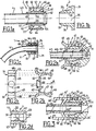
- les figures 1a, 1b et 1c représentent en coupe longitudinale respectivement un raccord selon un premier mode de réalisation de l'invention, un embout qui lui correspond, et une liaison étanche comportant ledit raccord monté sur l'embout par encliquetage,
- les figures 2a à 2d représentent respectivement une deuxième mode de réalisation d'un raccord selon l'invention, monté sur un embout, pour former une liaison étanche (Fig. 2a), une vue en coupe longitudinale du dispositif d'accrochage (Fig. 2b), une vue suivant A du dispositif d'accrochage, et une vue en coupe de l'élément d'étanchéité (Fig. 2d),
- la figure 3 représente un mode de réalisation préféré d'un raccord selon l'invention, représenté monté sur un embout pour former une liaison étanche.
- et les figures 4a et 4b représentent en perspective une autre variante de raccord selon l'invention, avant et après pré-assemblage par mise en butée.
- FIGS. 1a, 1b and 1c represent in longitudinal section respectively a coupling according to a first embodiment of the invention, a nozzle corresponding thereto, and a sealed connection comprising said coupling mounted on the tip by snapping,
- Figures 2a to 2d respectively show a second embodiment of a coupling according to the invention, mounted on a nozzle, to form a tight connection (Figure 2a), a longitudinal sectional view of the attachment device (Fig. 2b), a view A of the coupling device, and a sectional view of the sealing element (FIG.
- Figure 3 shows a preferred embodiment of a coupling according to the invention, shown mounted on a nozzle to form a tight connection.
- and FIGS. 4a and 4b show in perspective another variant of connection according to the invention, before and after pre-assembly by abutment.
L'invention met en oeuvre un raccord rapide pré-assemblé sur un tube 4 rigide ou semi-rigide (c'est-à-dire suffisamment rigide pour assurer une étanchéité), par exemple en métal ou en matière plastique, qui est mis en forme à son extrémité avant 42 pour former un bourrelet annulaire 41. Cette mise en forme peut s'effectuer à froid, ou à chaud. Un élément d'étanchéité 5 en élastomère, par exemple en caoutchouc, enfilé sur le tube 4 (ou surmoulé sur celui-ci) permet d'assurer l'étanchéité sur le tube 4 et sur l'embout 3 par compression, grâce à un dispositif d'accrochage 6, par exemple en métal ou en matériau thermoplastique qui est enfilé sur le tube 4 et qui vient se raccorder sur l'embout 3 qui peut être d'un type classique, par exemple un embout couramment utilisé par les constructeurs automobiles dans les circuits de refroidissement. Le dispositif d'accrochage 6 peut être enfilé, notamment à force, ou surmoulé sur le tube 4.The invention uses a quick coupling pre-assembled on a rigid or semi-rigid tube (that is to say rigid enough to ensure a seal), for example metal or plastic, which is put in place. form at its end before 42 to form an
Le raccord présente un nombre de composants correspondant chacun à une fonction, à savoir :
- un tube 4 pour le transfert de fluide,
- un
élément 5 en élastomère pour l'étanchéité, - et un
dispositif 6 pour l'accrochage, par exemple par encliquetage.
- a tube 4 for the transfer of fluid,
- an
elastomer element 5 for sealing, - and a
device 6 for attachment, for example by snapping.
Le raccord étant pré-assemblé, le montage s'effectue en une seule opération, par exemple par simple encliquetage.The fitting being pre-assembled, the assembly is carried out in a single operation, for example by simple snapping.
Aux figures 1a à 1c, le raccord pré-assemblé comporte un élément d'étanchéité 5 en élastomère, de forme générale cylindrique, dont le diamètre du contour interne 56 est sensiblement égal ou légèrement inférieur au diamètre du contour externe 43 du tube 4, pour lui permettre de glisser le long du tube 4. Pour améliorer l'étanchéité, l'élément 5 présente sur sa face cylindrique externe 57 et/ou sur son contour interne cylindrique 56 un ou plusieurs bourrelets annulaires 51 et/ou 52. Le tube 4 peut être formé pour permettre un dégagement à 90° ou selon un autre angle.In FIGS. 1a to 1c, the pre-assembled coupling comprises a generally cylindrical
En variante, l'élément 5 peut être surmoulé autour du tube 4. Le bourrelet annulaire 41 à l'extrémité avant du tube 4 sert de butée avant à la face avant 54 de l'élément d'étanchéité 5.Alternatively, the
Le dispositif d'accrochage 6 présente une région cylindrique 61 dont le contour interne 69 a un diamètre adapté à son coulissement le long du contour externe 43 du tube 4. Les moyens d'accrochage 6 sont par exemple constitués par des bras d'encliquetage 64 par exemple deux bras situés à 180° l'un de l'autre (comme à la figure 2c).The
Chaque bras 64 présente une région de rampe 66 pour un cliquet 63, qui vient s'encliqueter dans une rainure 34 d'une région cylindrique 32 de l'embout 3. Ces bras 64 sont par exemple articulés à partir d'une couronne annulaire 62. Une face avant 65 de la couronne 62 et/ou de la région 61 sert de butée arrière à la face arrière 55 de l'élément d'étanchéité 5. La région de rampe 66 coopère avec une région de rampe correspondante 33 de l'embout 3 pour faciliter l'approche du raccord 2 avant encliquetage, lequel s'effectue dans la position représentée à la figure 1c. Dans cette position, la face interne 67 des bras 64 jouxte les régions de rampe 33.Each
Dans cette position, les faces arrière 55 et avant 54 de l'élément 5 sont prises en butée entre la face 65 et le bourrelet 41.In this position, the
L'élément d'étanchéité 5 assure alors les deux fonctions d'étanchéité recherchées, par son contour interne 56 entre le tube 4 et le raccord 2 et par son contour externe 57, entre le raccord 2 et l'embout 3 pourvu d'une embase 31.The sealing
Dans la variante représentée aux figures 2a à 2d, un ergot de préhension 68 est associé à chaque bras 64 pour permettre son dégagement de la rainure 34' par effet de levier, en déformant légèrement la couronne annulaire 62. Dans ce mode de réalisation, les ergots 68 s'étendent vers l'extérieur du raccord pour faciliter la prise en main.In the variant shown in Figures 2a to 2d, a gripping
Dans la variante représentée à la figure 3, la couronne annulaire 62' et donc sa face avant 65' n'est pas plane, comme dans les modes de réalisation précédents, mais elle est concave et sa face avant 65' coopère avec une face complémentaire convexe de profil complémentaire 55' de l'élément d'étanchéité 5. Cette forme arrondie permet, par compression des ergots 68', un démontage facilité du raccord 2 par rapport à l'embout 3.In the variant shown in Figure 3, the annular ring 62 'and therefore its front face 65' is not flat, as in the previous embodiments, but it is concave and its front face 65 'cooperates with a complementary face convex of complementary profile 55 'of the sealing
En outre, les ergots 68' sont disposés dans le prolongement des bras 64 et ils présentent une extrémité 68" repliée par exemple à 90°, en direction de la région 61.In addition, the lugs 68 'are arranged in the extension of the
Ces extrémités 68" permettent, par effet de butée de l'extrémité 68", d'éviter de trop plier les ergots 68' lors du démontage du raccord 2.These ends 68 "make it possible, by the abutment effect of the
Dans la variante représentée aux figures 4a et 4b, l'extrémité annulaire 41 porte un méplat 45 de détrompage angulaire. Ce peut être également le cas du joint 5, avec un méplat d'extrémité 58, en vis-à-vis du méplat 45.In the variant shown in Figures 4a and 4b, the
Le méplat 45 permet de garantir l'orientation du tube (dans une rotation autour de son axe), contrairement à un embout sapin qui peut tourner. Cette indexation peut être indépendante de l'orientation des composants intermédiaires.The
D'autre part, la pièce d'accrochage 6 peut présenter une couronne cylindrique 71 jouxtant la face avant 65 et qui se prolonge vers l'avant par deux pattes 72 dont le contour interne 75 est apte à un emmanchement dans le périmètre du joint 5 en aval de sa face arrière 55. En position pré-assemblée (Fig. 4b), la face avant 73 de la couronne 71 est en butée sur la face arrière 55 du joint 5. Le joint 5 est en butée par sa face avant 53 sur l'extrémité annulaire 41 et l'emmanchement du contour interne 75 des pattes 72 autour du joint permet d'éviter une rotation de la pièce 6 autour du tube 4. On a ainsi réalisé un indexage angulaire des composants du raccord par rapport au méplat 45, qui est demandé dans certaines applications où la pièce 6 doit être positionnée selon une position angulaire précise par rapport au méplat 45.On the other hand, the
En variante, cette orientation angulaire peut être obtenue par emmanchement à force de la pièce 6 sur le tube 4, avec mise en oeuvre éventuelle des pattes d'indexation 72.As a variant, this angular orientation can be obtained by force-fitting the
L'indexation angulaire par le méplat 45 permet de repérer angulairement un dégagement du tube (à 90° ou selon un autre angle), pour le montage de l'embase. Il n'y a pas besoin pour cela de modifier les éléments qui composent le raccord. Autrement dit, il y a un seul type de raccord qui permet tous les dégagements angulaires, contrairement à l'Art. Antérieur, où il faut adapter les pièces de raccords.The angular indexing by the
L'invention permet de réaliser des raccordements de tubes de transport de fluide (eau, antigel, huile, carburant, air, fluide frigorigène de circuit de climatisation) plus particulièrement dans le domaine automobile.The invention makes it possible to make connections for fluid transport tubes (water, antifreeze, oil, fuel, air, refrigerant air conditioning circuit) more particularly in the automotive field.
Un autre avantage de l'invention est que seuls le tube 4 et le joint 5 doivent résister au fluide.Another advantage of the invention is that only the tube 4 and the
L'invention peut s'appliquer en particulier au circuit de dégazage d'un circuit de refroidissement automobile.The invention can be applied in particular to the degassing circuit of an automobile cooling circuit.
Claims (16)
- A pre-assembled coupling for leaktight coupling of a fluid transport tube and an endpiece provided with at least one fastener element having a groove in an outer cylindrical region, the coupling being characterized in that it comprises:· a said tube (4), which tube presents an annular bead (41) at a front end (42);· a fastener device (6) slid onto said tube (4) and presenting at least one arm (63, 64) forming a snap-fastening element that comes to snap-fasten in a groove (34) of an outer cylindrical region (32) of the endpiece (3); and· a cylindrical elastomer sealing element (5) disposed around said tube (4) and housed between the fastener device (6) and the annular bead (41), said sealing element (5) presenting an inner sealing surface (56) for sealing relative to an outside surface (43) of the tube (4), and an outer sealing surface (57) for sealing relative to inner surface of the endpiece (3).
- A coupling according to claim 1, characterized in that the fastener device (6) presents at least one grip member (68) exerting a lever effect on a fastener element (64, 66) to enable the coupling (2) to be uncoupled from the endpiece (3).
- A coupling according to claim 1 or claim 2, characterized in that the fastener device (6) presents a cylindrical region (61, 69) slidable along the tube (4).
- A coupling according to claim 1 or claim 2, characterized in that the fastener device (6) presents a cylindrical region (61, 69) slidable under force along the tube (4).
- A coupling according to any preceding claim, characterized in that the fastener device (6) presents a face (65, 65') forming a rear abutment (55, 55') for the sealing element (5).
- A coupling according to claim 5, characterized in that said face (65) is plane.
- A coupling according to claim 5, characterized in that said face (65') is concave, and in that the sealing element (5) presents a convex face (55') complementary to said concave face (65').
- A coupling according to any preceding claim, characterized in that at least one of said arms (63, 64) is connected to a said annular ring (62) of the fastener device (6).
- A coupling according to claim 8, characterized in that at least one grip member (68) is connected to said annular ring (62).
- A coupling according to any preceding claim, characterized in that the annular bead (41) and/or the front portion of the gasket (5) presents at its periphery an angular indexing element (45, 58), in particular a flat.
- A coupling according to any preceding claim, characterized in that the fastener device (6) presents at least one element (72) suitable for being engaged by force against the inner perimeter of the rear portion of the gasket (5).
- A coupling according to any preceding claim, characterized in that it is pre-assembled with the fastener device (6) being put into abutment against the gasket (5) and with the gasket (5) being put into abutment against the annular bead (41).
- A coupling according to claims 11 and 12, characterized in that the fastener device (6) is pre-assembled, being angularly indexed relative to said angular indexing element (45, 58).
- A leaktight connection between a transport tube and an endpiece, characterized in that it comprises a coupling (2) according to any preceding claim assembled with the endpiece (3) by co-operation between the fastener elements (63, 34) of the fastener device (6) and of the endpiece (3).
- A leaktight connection according to claim 14, characterized in that the sealing element (5) is prevented from moving by being held in abutment (53, 55) between the annular bead (41) of the tube (4) and the fastener device (6).
- A leaktight connection according to claim 15, characterized in that the coupling presents at least one said angular indexing element (45, 58), and in that the fastener device (6) is angularly indexed relative to said angular indexing element (45, 58).
Applications Claiming Priority (3)
| Application Number | Priority Date | Filing Date | Title |
|---|---|---|---|
| FR0111405 | 2001-09-04 | ||
| FR0111405A FR2829219B1 (en) | 2001-09-04 | 2001-09-04 | PRE-ASSEMBLED SEALING FITTING |
| PCT/FR2002/002997 WO2003025450A1 (en) | 2001-09-04 | 2002-09-03 | Pre-assembled sealing connection |
Publications (2)
| Publication Number | Publication Date |
|---|---|
| EP1423636A1 EP1423636A1 (en) | 2004-06-02 |
| EP1423636B1 true EP1423636B1 (en) | 2006-01-11 |
Family
ID=8866933
Family Applications (1)
| Application Number | Title | Priority Date | Filing Date |
|---|---|---|---|
| EP02798756A Revoked EP1423636B1 (en) | 2001-09-04 | 2002-09-03 | Pre-assembled sealing connection |
Country Status (10)
| Country | Link |
|---|---|
| US (1) | US20040232696A1 (en) |
| EP (1) | EP1423636B1 (en) |
| AT (1) | ATE315757T1 (en) |
| BR (1) | BR0212171A (en) |
| DE (1) | DE60208715T2 (en) |
| FR (1) | FR2829219B1 (en) |
| MX (1) | MXPA04002044A (en) |
| PL (1) | PL369430A1 (en) |
| PT (1) | PT1423636E (en) |
| WO (1) | WO2003025450A1 (en) |
Families Citing this family (62)
| Publication number | Priority date | Publication date | Assignee | Title |
|---|---|---|---|---|
| DE10250421A1 (en) * | 2002-10-30 | 2004-05-13 | A. Raymond & Cie | connecting element |
| US20050082828A1 (en) | 2003-09-12 | 2005-04-21 | Wicks Jeffrey C. | Releasable connection assembly for joining tubing sections |
| JP2007512102A (en) | 2003-11-20 | 2007-05-17 | ザ ヘンリー エム. ジャクソン ファウンデーション フォー ザ アドヴァンスメント オブ ミリタリー メディシン, インク. | Portable manual pump for fluid suction |
| US8337475B2 (en) * | 2004-10-12 | 2012-12-25 | C. R. Bard, Inc. | Corporeal drainage system |
| US7448653B2 (en) | 2005-06-10 | 2008-11-11 | Value Plastics, Inc. | Female connector for releasable coupling with a male connector defining a fluid conduit |
| US7806139B2 (en) | 2006-01-20 | 2010-10-05 | Value Plastics, Inc. | Fluid conduit coupling assembly having male and female couplers with integral valves |
| DE102006011617A1 (en) * | 2006-03-14 | 2007-09-20 | Norma Germany Gmbh | Connecting arrangement for connecting a pipe socket with a hose |
| US20090058082A1 (en) * | 2007-09-05 | 2009-03-05 | Green Ronald D | Two-part quick connect retention attachment for flexible tubing in a water supply system |
| US8613203B2 (en) * | 2007-11-05 | 2013-12-24 | Lg Electronics Inc. | Refrigerator and control method thereof |
| USD654573S1 (en) | 2007-11-19 | 2012-02-21 | Value Plastics, Inc. | Female quick connect fitting |
| DE202008000145U1 (en) * | 2008-01-02 | 2009-05-20 | Voss Automotive Gmbh | Connection system for fluid-carrying systems |
| DE102008015811A1 (en) * | 2008-03-27 | 2009-10-01 | Fte Automotive Gmbh | Detachable plug connection for pipelines or the like |
| US8235426B2 (en) | 2008-07-03 | 2012-08-07 | Nordson Corporation | Latch assembly for joining two conduits |
| USD634840S1 (en) | 2008-07-03 | 2011-03-22 | Value Plastics, Inc. | Female body of connector for fluid tubing |
| USD630320S1 (en) | 2008-07-03 | 2011-01-04 | Value Plastics, Inc. | Connector for fluid tubing |
| USD629894S1 (en) | 2008-07-03 | 2010-12-28 | Value Plastics, Inc. | Male body of connector for fluid tubing |
| EP2158935B1 (en) * | 2008-08-29 | 2014-07-16 | Dräger Medical GmbH | Connector for medicinal tubes |
| DE102008061462B4 (en) * | 2008-12-10 | 2011-04-14 | Illinois Tool Works Inc., Glenview | Cooling system for an internal combustion engine |
| FR2939864B1 (en) * | 2008-12-12 | 2010-12-03 | Cie Mediterraneenne Des Cafes | CONNECTOR, SYSTEM AND METHOD FOR CONNECTING TWO HYDRAULIC ORGANS. |
| USD655393S1 (en) | 2009-06-23 | 2012-03-06 | Value Plastics, Inc. | Multi-port valve |
| USD649240S1 (en) | 2009-12-09 | 2011-11-22 | Value Plastics, Inc. | Male dual lumen bayonet connector |
| USD783815S1 (en) | 2009-12-09 | 2017-04-11 | General Electric Company | Male dual lumen bayonet connector |
| US9388929B2 (en) | 2009-12-09 | 2016-07-12 | Nordson Corporation | Male bayonet connector |
| US10711930B2 (en) | 2009-12-09 | 2020-07-14 | Nordson Corporation | Releasable connection assembly |
| JP5714028B2 (en) | 2009-12-23 | 2015-05-07 | ノードソン コーポレーションNordson Corporation | Fluid connector latch with profile retraction |
| CN102753876B (en) | 2009-12-23 | 2015-07-22 | 诺信公司 | Button latch with integrally molded cantilever springs |
| US8920956B2 (en) | 2010-08-23 | 2014-12-30 | Lg Chem, Ltd. | Battery system and manifold assembly having a manifold member and a connecting fitting |
| US8353315B2 (en) | 2010-08-23 | 2013-01-15 | Lg Chem, Ltd. | End cap |
| US8469404B2 (en) * | 2010-08-23 | 2013-06-25 | Lg Chem, Ltd. | Connecting assembly |
| US8758922B2 (en) | 2010-08-23 | 2014-06-24 | Lg Chem, Ltd. | Battery system and manifold assembly with two manifold members removably coupled together |
| USD663022S1 (en) | 2011-02-11 | 2012-07-03 | Nordson Corporation | Male body of connector for fluid tubing |
| USD652510S1 (en) | 2011-02-11 | 2012-01-17 | Value Plastics, Inc. | Connector for fluid tubing |
| USD652511S1 (en) | 2011-02-11 | 2012-01-17 | Value Plastics, Inc. | Female body of connector for fluid tubing |
| USD699841S1 (en) | 2011-07-29 | 2014-02-18 | Nordson Corporation | Female body of connector for fluid tubing |
| USD698440S1 (en) | 2011-07-29 | 2014-01-28 | Nordson Corporation | Connector for fluid tubing |
| USD699840S1 (en) | 2011-07-29 | 2014-02-18 | Nordson Corporation | Male body of connector for fluid tubing |
| CN102506393B (en) * | 2011-10-27 | 2014-05-14 | 深圳市华星光电技术有限公司 | Backlight module and connection device thereof |
| USD709612S1 (en) | 2011-12-23 | 2014-07-22 | Nordson Corporation | Female dual lumen connector |
| DE102012102191A1 (en) * | 2012-03-15 | 2013-09-19 | Voss Automotive Gmbh | "Plug-in connection system, in particular for fluidic lines, fittings or aggregates" |
| JP2012139554A (en) * | 2012-04-26 | 2012-07-26 | Jms Co Ltd | Lock connector for communication |
| DE102012104288A1 (en) * | 2012-05-16 | 2013-11-21 | Voss Automotive Gmbh | "Connector for fluid lines and holding part for such a connector" |
| US8974934B2 (en) | 2012-08-16 | 2015-03-10 | Lg Chem, Ltd. | Battery module |
| JP2015533362A (en) * | 2012-11-02 | 2015-11-24 | アドバンスト テクノロジー マテリアルズ,インコーポレイテッド | Dip tube assembly and method of manufacturing the same |
| CN103225723A (en) * | 2013-03-26 | 2013-07-31 | 安徽省华久管业有限公司 | Novel plastic pipe connector |
| DE102013208548A1 (en) | 2013-05-08 | 2014-11-13 | Labomatic Instruments Ag | Connection system and method for connecting fluid-carrying components |
| JP6250982B2 (en) * | 2013-08-27 | 2017-12-20 | ニプロ株式会社 | Locking member for connector connection |
| CN104019308A (en) * | 2014-06-26 | 2014-09-03 | 李婧 | Hot water pipe joint |
| GB2549713A (en) * | 2016-04-25 | 2017-11-01 | Perkins Engines Co Ltd | Leak off clip for fuel injectors |
| AU2017299466B2 (en) | 2016-07-18 | 2022-07-14 | Merit Medical Systems, Inc. | Inflatable radial artery compression device |
| USD838366S1 (en) | 2016-10-31 | 2019-01-15 | Nordson Corporation | Blood pressure connector |
| FI3354955T3 (en) * | 2017-01-30 | 2023-06-20 | Georg Fischer Harvel Llc | Pipe coupler and coupling method |
| DE102017002395B4 (en) * | 2017-03-14 | 2024-03-21 | Stiebel Eltron Gmbh & Co. Kg | Connection piece for connecting to a building technology device and method for assembling a connection piece |
| US10781958B2 (en) | 2017-10-31 | 2020-09-22 | Oetiker Ny, Inc. | Low peak insertion tube end form |
| JP6493705B2 (en) * | 2017-11-24 | 2019-04-03 | ニプロ株式会社 | Locking member for connector connection |
| JP7174945B2 (en) * | 2018-05-18 | 2022-11-18 | 株式会社ジェイ・エム・エス | indwelling needle device |
| DE112019002531T5 (en) * | 2018-05-18 | 2021-02-18 | Hiroshima University | Indwelling cannula device |
| DE102018008709A1 (en) * | 2018-11-06 | 2020-05-07 | Ferdinand Müller-Niksic | Quick-release fastener |
| DE102019112239A1 (en) * | 2019-05-10 | 2020-11-12 | Mahle International Gmbh | Heat exchanger |
| FR3102528B1 (en) * | 2019-10-28 | 2021-10-15 | Sogefi Filtration Spa | DUCT CONNECTION DEVICE |
| DE102020104170A1 (en) * | 2020-02-18 | 2021-08-19 | Bayerische Motoren Werke Aktiengesellschaft | Connection device for a transmission ventilator |
| US11293576B2 (en) * | 2020-08-31 | 2022-04-05 | Caremed Supply Inc. | Gas supply connector |
| WO2024056119A1 (en) * | 2022-09-14 | 2024-03-21 | Schaeffler Technologies AG & Co. KG | Housing arrangement comprising a pressure adapter mounted on a wall element; and drive device |
Family Cites Families (14)
| Publication number | Priority date | Publication date | Assignee | Title |
|---|---|---|---|---|
| DE3444817A1 (en) * | 1984-01-20 | 1985-07-25 | Rasmussen Gmbh, 6457 Maintal | CONNECTOR |
| JPS6150888U (en) * | 1984-09-07 | 1986-04-05 | ||
| FR2617943B1 (en) | 1987-07-06 | 1990-10-05 | Inventa Ag | QUICK COUPLER FOR CONNECTING FLEXIBLE OR RIGID DUCT |
| JPH0674875B2 (en) | 1988-12-07 | 1994-09-21 | エムス − インヴエンタ・アクチエンゲゼルシヤフト | Quick disconnect joint |
| US5123677A (en) * | 1990-05-31 | 1992-06-23 | Swagelok-Quick Connect Co. | All plastic quick-connect coupling |
| IT220447Z2 (en) * | 1990-06-08 | 1993-09-22 | Italiana Serrature Torino | CONNECTION GROUP FOR CIRCUITS OF CIRCULATION OF THE COOLANT LIQUID OF A VEHICLE ENGINE |
| FR2665507B1 (en) * | 1990-07-31 | 1992-11-27 | Hutchinson Sa | DEVICE FOR THE QUICK ASSEMBLY OF A HOSE TO A HEAT EXCHANGER OF A MOTOR VEHICLE. |
| JP3104929B2 (en) * | 1992-03-11 | 2000-10-30 | 臼井国際産業株式会社 | Small diameter pipe connection fitting |
| JP3148857B2 (en) * | 1997-11-10 | 2001-03-26 | 日本ピラー工業株式会社 | Resin pipe fittings |
| US6155607A (en) * | 1998-02-17 | 2000-12-05 | Parker-Hannifin Corporation | Quick connect coupling |
| US6199919B1 (en) * | 1998-03-31 | 2001-03-13 | Tokai Rubber Industries, Ltd. | Tube connecting structure |
| US6481759B1 (en) * | 1999-03-31 | 2002-11-19 | Tokai Rubber Industries, Ltd. | Connecting structure |
| US6173994B1 (en) * | 1999-08-20 | 2001-01-16 | Ti Group Automotive Systems Corp. | Coupling assemblies for providing fluid connection |
| JP3452196B2 (en) * | 2000-08-31 | 2003-09-29 | 株式会社フロウエル | Tube fitting and its construction method |
-
2001
- 2001-09-04 FR FR0111405A patent/FR2829219B1/en not_active Expired - Lifetime
-
2002
- 2002-09-02 US US10/488,389 patent/US20040232696A1/en not_active Abandoned
- 2002-09-03 MX MXPA04002044A patent/MXPA04002044A/en active IP Right Grant
- 2002-09-03 DE DE60208715T patent/DE60208715T2/en not_active Revoked
- 2002-09-03 BR BR0212171-9A patent/BR0212171A/en active Search and Examination
- 2002-09-03 AT AT02798756T patent/ATE315757T1/en not_active IP Right Cessation
- 2002-09-03 WO PCT/FR2002/002997 patent/WO2003025450A1/en not_active Application Discontinuation
- 2002-09-03 PL PL02369430A patent/PL369430A1/en unknown
- 2002-09-03 EP EP02798756A patent/EP1423636B1/en not_active Revoked
- 2002-09-03 PT PT02798756T patent/PT1423636E/en unknown
Also Published As
| Publication number | Publication date |
|---|---|
| MXPA04002044A (en) | 2004-06-07 |
| WO2003025450A1 (en) | 2003-03-27 |
| US20040232696A1 (en) | 2004-11-25 |
| DE60208715T2 (en) | 2006-08-24 |
| FR2829219B1 (en) | 2004-12-17 |
| PT1423636E (en) | 2006-05-31 |
| ATE315757T1 (en) | 2006-02-15 |
| BR0212171A (en) | 2004-07-20 |
| PL369430A1 (en) | 2005-04-18 |
| DE60208715D1 (en) | 2006-04-06 |
| EP1423636A1 (en) | 2004-06-02 |
| FR2829219A1 (en) | 2003-03-07 |
Similar Documents
| Publication | Publication Date | Title |
|---|---|---|
| EP1423636B1 (en) | Pre-assembled sealing connection | |
| EP1064489B1 (en) | Snap-on pipe fitting | |
| EP0840867B1 (en) | Device forming a leak-proof connection between a rigid tube end and a flexible pipe, and method for making same | |
| EP3014159B1 (en) | Fluid connector with clamp and protection | |
| EP0360634B1 (en) | Connection device between a hose coupling and the rigid pipe end of a pressure circuit | |
| EP1493958B1 (en) | Annular seal for fluid transfer connector and connector equiped with such a seal | |
| EP0753697A1 (en) | Quick acting coupling device between a pipeline and a joint, especially for a heat exchanger, and heat exchanger comprising this device | |
| EP3036463B1 (en) | Bead seal and connection device comprising such a seal | |
| FR2738893A1 (en) | METHOD OF MAKING A BIT, TIP AND CONNECTOR PRODUCED BY THIS METHOD AND CIRCUIT COMPRISING SUCH A CONNECTOR | |
| EP1941201B1 (en) | Connecting device with welded body | |
| FR3064713A1 (en) | METHOD FOR MANUFACTURING A FLUIDIC ARRANGEMENT AND ASSOCIATED FLUIDIC ARRANGEMENT | |
| WO2000079172A1 (en) | Device for sealed connection of fluid conduit, particularly for motor vehicle | |
| EP1533558B1 (en) | Coaxial pipe coupling | |
| EP1056969A1 (en) | Snap-on connection for fluid conduit | |
| EP1291568A1 (en) | Quick-acting coupling for deformable pipes | |
| EP2369213B1 (en) | Quick connector with snapable hose into a coupling, hose connecting process thereof | |
| EP0338880B1 (en) | Coupling-device between a soft joint element and a rigid pipe end for a pressurised fluid system | |
| WO2000050798A1 (en) | Sealing device and fitting equipped therewith | |
| FR2787171A1 (en) | REMOVABLE CONNECTION DEVICE FOR THE CONNECTION OF A RIGID OR SEMI-RIGID TUBE AND A RIGID INTERFACE | |
| FR2628819A1 (en) | Flexible connection for hose - is used in vehicle cooling system and incorporates external groove in clamping sleeve | |
| EP3215779A1 (en) | Device for coupling a rigid male endpiece to a flexible female pipe, and production method therefor | |
| EP0327443A1 (en) | Connection between a heat exchanger and a tubular member | |
| FR2927978A1 (en) | Rectilinear conduit's end portion shaping device for e.g. coupling of connection assembly, has sleeve surrounding end portion of conduit and comprising preservation unit for preserving bend of sleeve against flexural elasticity of conduit | |
| FR2962187A1 (en) | DEVICE AND METHOD FOR CONNECTING ESPECIALLY FOR WATER COOLING CIRCUIT OF MOTOR VEHICLE. | |
| FR3098880A1 (en) | Fluidic connection for fluid transfer. |
Legal Events
| Date | Code | Title | Description |
|---|---|---|---|
| PUAI | Public reference made under article 153(3) epc to a published international application that has entered the european phase |
Free format text: ORIGINAL CODE: 0009012 |
|
| 17P | Request for examination filed |
Effective date: 20040220 |
|
| AK | Designated contracting states |
Kind code of ref document: A1 Designated state(s): AT BE BG CH CY CZ DE DK EE ES FI FR GB GR IE IT LI LU MC NL PT SE SK TR |
|
| AX | Request for extension of the european patent |
Extension state: AL LT LV MK RO SI |
|
| 17Q | First examination report despatched |
Effective date: 20050221 |
|
| GRAP | Despatch of communication of intention to grant a patent |
Free format text: ORIGINAL CODE: EPIDOSNIGR1 |
|
| GRAS | Grant fee paid |
Free format text: ORIGINAL CODE: EPIDOSNIGR3 |
|
| GRAA | (expected) grant |
Free format text: ORIGINAL CODE: 0009210 |
|
| AK | Designated contracting states |
Kind code of ref document: B1 Designated state(s): AT BE BG CH CY CZ DE DK EE ES FI FR GB GR IE IT LI LU MC NL PT SE SK TR |
|
| PG25 | Lapsed in a contracting state [announced via postgrant information from national office to epo] |
Ref country code: IT Free format text: LAPSE BECAUSE OF FAILURE TO SUBMIT A TRANSLATION OF THE DESCRIPTION OR TO PAY THE FEE WITHIN THE PRESCRIBED TIME-LIMIT;WARNING: LAPSES OF ITALIAN PATENTS WITH EFFECTIVE DATE BEFORE 2007 MAY HAVE OCCURRED AT ANY TIME BEFORE 2007. THE CORRECT EFFECTIVE DATE MAY BE DIFFERENT FROM THE ONE RECORDED. Effective date: 20060111 Ref country code: NL Free format text: LAPSE BECAUSE OF FAILURE TO SUBMIT A TRANSLATION OF THE DESCRIPTION OR TO PAY THE FEE WITHIN THE PRESCRIBED TIME-LIMIT Effective date: 20060111 Ref country code: FI Free format text: LAPSE BECAUSE OF FAILURE TO SUBMIT A TRANSLATION OF THE DESCRIPTION OR TO PAY THE FEE WITHIN THE PRESCRIBED TIME-LIMIT Effective date: 20060111 Ref country code: IE Free format text: LAPSE BECAUSE OF FAILURE TO SUBMIT A TRANSLATION OF THE DESCRIPTION OR TO PAY THE FEE WITHIN THE PRESCRIBED TIME-LIMIT Effective date: 20060111 Ref country code: GB Free format text: LAPSE BECAUSE OF FAILURE TO SUBMIT A TRANSLATION OF THE DESCRIPTION OR TO PAY THE FEE WITHIN THE PRESCRIBED TIME-LIMIT Effective date: 20060111 Ref country code: AT Free format text: LAPSE BECAUSE OF FAILURE TO SUBMIT A TRANSLATION OF THE DESCRIPTION OR TO PAY THE FEE WITHIN THE PRESCRIBED TIME-LIMIT Effective date: 20060111 |
|
| REG | Reference to a national code |
Ref country code: CH Ref legal event code: EP |
|
| REG | Reference to a national code |
Ref country code: IE Ref legal event code: FG4D Free format text: LANGUAGE OF EP DOCUMENT: FRENCH |
|
| REF | Corresponds to: |
Ref document number: 60208715 Country of ref document: DE Date of ref document: 20060406 Kind code of ref document: P |
|
| PG25 | Lapsed in a contracting state [announced via postgrant information from national office to epo] |
Ref country code: DK Free format text: LAPSE BECAUSE OF FAILURE TO SUBMIT A TRANSLATION OF THE DESCRIPTION OR TO PAY THE FEE WITHIN THE PRESCRIBED TIME-LIMIT Effective date: 20060411 Ref country code: SE Free format text: LAPSE BECAUSE OF FAILURE TO SUBMIT A TRANSLATION OF THE DESCRIPTION OR TO PAY THE FEE WITHIN THE PRESCRIBED TIME-LIMIT Effective date: 20060411 |
|
| PG25 | Lapsed in a contracting state [announced via postgrant information from national office to epo] |
Ref country code: ES Free format text: LAPSE BECAUSE OF FAILURE TO SUBMIT A TRANSLATION OF THE DESCRIPTION OR TO PAY THE FEE WITHIN THE PRESCRIBED TIME-LIMIT Effective date: 20060422 |
|
| REG | Reference to a national code |
Ref country code: PT Ref legal event code: SC4A Effective date: 20060404 |
|
| NLV1 | Nl: lapsed or annulled due to failure to fulfill the requirements of art. 29p and 29m of the patents act | ||
| PGFP | Annual fee paid to national office [announced via postgrant information from national office to epo] |
Ref country code: FR Payment date: 20060728 Year of fee payment: 5 |
|
| GBV | Gb: ep patent (uk) treated as always having been void in accordance with gb section 77(7)/1977 [no translation filed] |
Effective date: 20060111 |
|
| REG | Reference to a national code |
Ref country code: IE Ref legal event code: FD4D |
|
| PGFP | Annual fee paid to national office [announced via postgrant information from national office to epo] |
Ref country code: TR Payment date: 20060829 Year of fee payment: 5 |
|
| PGFP | Annual fee paid to national office [announced via postgrant information from national office to epo] |
Ref country code: PT Payment date: 20060831 Year of fee payment: 5 |
|
| PGFP | Annual fee paid to national office [announced via postgrant information from national office to epo] |
Ref country code: SK Payment date: 20060904 Year of fee payment: 5 |
|
| PGFP | Annual fee paid to national office [announced via postgrant information from national office to epo] |
Ref country code: EE Payment date: 20060919 Year of fee payment: 5 |
|
| PGFP | Annual fee paid to national office [announced via postgrant information from national office to epo] |
Ref country code: DE Payment date: 20060926 Year of fee payment: 5 |
|
| PG25 | Lapsed in a contracting state [announced via postgrant information from national office to epo] |
Ref country code: BE Free format text: LAPSE BECAUSE OF NON-PAYMENT OF DUE FEES Effective date: 20060930 Ref country code: LI Free format text: LAPSE BECAUSE OF NON-PAYMENT OF DUE FEES Effective date: 20060930 Ref country code: MC Free format text: LAPSE BECAUSE OF NON-PAYMENT OF DUE FEES Effective date: 20060930 Ref country code: CH Free format text: LAPSE BECAUSE OF NON-PAYMENT OF DUE FEES Effective date: 20060930 |
|
| PLBI | Opposition filed |
Free format text: ORIGINAL CODE: 0009260 |
|
| 26 | Opposition filed |
Opponent name: VERITAS AG Effective date: 20060927 |
|
| PLAX | Notice of opposition and request to file observation + time limit sent |
Free format text: ORIGINAL CODE: EPIDOSNOBS2 |
|
| REG | Reference to a national code |
Ref country code: CH Ref legal event code: PL |
|
| BERE | Be: lapsed |
Owner name: HUTCHINSON Effective date: 20060930 |
|
| PG25 | Lapsed in a contracting state [announced via postgrant information from national office to epo] |
Ref country code: GR Free format text: LAPSE BECAUSE OF FAILURE TO SUBMIT A TRANSLATION OF THE DESCRIPTION OR TO PAY THE FEE WITHIN THE PRESCRIBED TIME-LIMIT Effective date: 20060412 |
|
| PGFP | Annual fee paid to national office [announced via postgrant information from national office to epo] |
Ref country code: CZ Payment date: 20060828 Year of fee payment: 5 |
|
| PG25 | Lapsed in a contracting state [announced via postgrant information from national office to epo] |
Ref country code: PT Free format text: LAPSE BECAUSE OF NON-PAYMENT OF DUE FEES Effective date: 20080303 Ref country code: CZ Free format text: LAPSE BECAUSE OF NON-PAYMENT OF DUE FEES Effective date: 20070903 |
|
| REG | Reference to a national code |
Ref country code: EE Ref legal event code: MM4A Ref document number: E000375 Country of ref document: EE Effective date: 20070930 |
|
| PG25 | Lapsed in a contracting state [announced via postgrant information from national office to epo] |
Ref country code: LU Free format text: LAPSE BECAUSE OF NON-PAYMENT OF DUE FEES Effective date: 20060903 Ref country code: EE Free format text: LAPSE BECAUSE OF NON-PAYMENT OF DUE FEES Effective date: 20070930 Ref country code: DE Free format text: LAPSE BECAUSE OF NON-PAYMENT OF DUE FEES Effective date: 20080401 |
|
| PGFP | Annual fee paid to national office [announced via postgrant information from national office to epo] |
Ref country code: BG Payment date: 20060929 Year of fee payment: 5 |
|
| PG25 | Lapsed in a contracting state [announced via postgrant information from national office to epo] |
Ref country code: SK Free format text: LAPSE BECAUSE OF NON-PAYMENT OF DUE FEES Effective date: 20070903 |
|
| REG | Reference to a national code |
Ref country code: FR Ref legal event code: ST Effective date: 20080531 |
|
| RDAF | Communication despatched that patent is revoked |
Free format text: ORIGINAL CODE: EPIDOSNREV1 |
|
| PG25 | Lapsed in a contracting state [announced via postgrant information from national office to epo] |
Ref country code: FR Free format text: LAPSE BECAUSE OF NON-PAYMENT OF DUE FEES Effective date: 20071001 |
|
| PG25 | Lapsed in a contracting state [announced via postgrant information from national office to epo] |
Ref country code: CY Free format text: LAPSE BECAUSE OF FAILURE TO SUBMIT A TRANSLATION OF THE DESCRIPTION OR TO PAY THE FEE WITHIN THE PRESCRIBED TIME-LIMIT Effective date: 20060111 |
|
| RDAG | Patent revoked |
Free format text: ORIGINAL CODE: 0009271 |
|
| STAA | Information on the status of an ep patent application or granted ep patent |
Free format text: STATUS: PATENT REVOKED |
|
| REG | Reference to a national code |
Ref country code: PT Ref legal event code: MP4A Effective date: 20090116 |
|
| 27W | Patent revoked |
Effective date: 20080929 |
|
| PG25 | Lapsed in a contracting state [announced via postgrant information from national office to epo] |
Ref country code: TR Free format text: LAPSE BECAUSE OF FAILURE TO SUBMIT A TRANSLATION OF THE DESCRIPTION OR TO PAY THE FEE WITHIN THE PRESCRIBED TIME-LIMIT Effective date: 20060111 |
|
| PG25 | Lapsed in a contracting state [announced via postgrant information from national office to epo] |
Ref country code: BG Free format text: LAPSE BECAUSE OF NON-PAYMENT OF DUE FEES Effective date: 20080331 |