EP0753293B1 - Vorrichtung zur Verabreichung von Substanzen, insbesondere Inhalationspräparate - Google Patents
Vorrichtung zur Verabreichung von Substanzen, insbesondere Inhalationspräparate Download PDFInfo
- Publication number
- EP0753293B1 EP0753293B1 EP96101748A EP96101748A EP0753293B1 EP 0753293 B1 EP0753293 B1 EP 0753293B1 EP 96101748 A EP96101748 A EP 96101748A EP 96101748 A EP96101748 A EP 96101748A EP 0753293 B1 EP0753293 B1 EP 0753293B1
- Authority
- EP
- European Patent Office
- Prior art keywords
- housing
- dispensing head
- dispensing
- pressurized container
- plastic
- Prior art date
- Legal status (The legal status is an assumption and is not a legal conclusion. Google has not performed a legal analysis and makes no representation as to the accuracy of the status listed.)
- Expired - Lifetime
Links
Images


Classifications
-
- A—HUMAN NECESSITIES
- A61—MEDICAL OR VETERINARY SCIENCE; HYGIENE
- A61M—DEVICES FOR INTRODUCING MEDIA INTO, OR ONTO, THE BODY; DEVICES FOR TRANSDUCING BODY MEDIA OR FOR TAKING MEDIA FROM THE BODY; DEVICES FOR PRODUCING OR ENDING SLEEP OR STUPOR
- A61M15/00—Inhalators
- A61M15/009—Inhalators using medicine packages with incorporated spraying means, e.g. aerosol cans
Definitions
- the invention relates to a device for administering substances, in particular inhalation preparations (aerosols), with overpressure, comprising a pressure vessel made of glass, which contains at least a supply of a substance to be dispensed and at least one propellant, and which has an outlet opening on which a dispensing member is attached , a burst and splinter protection made of plastic, formed by a self-supporting housing that surrounds the pressure vessel and completely surrounds the dispensing element with the exception of the outlet opening, and pressure outlet openings in the housing, a dispensing button, which interacts with the dispensing element in such a way that when both parts are pressed against one another, the dispensing element is actuated, and a certain amount of the at least one substance to be dispensed passes through the outlet opening and is expelled in the form of at least one jet from a spray opening in the dispensing head.
- a pressure vessel made of glass, which contains at least a supply of a substance to be dispensed
- the pressure vessel of the device described above has the shape of a vial.
- the volume of the bottle can be 5 - 50 ml be.
- the outlet opening is located at the top of the bottle. This is usually done by pressing and / or flaring a delivery element on the pressure vessel, for example a metering valve with a mostly cylindrical cannula protruding from the top, often using an elastic cannula Seal between head and dosing valve, closed.
- the pressure vessel is filled in such a way that the substance (s) to be dispensed introduced beforehand or together with the blowing agent (s) the dosing valve are pressed in.
- the pressure vessel is placed in a cylindrical one Part inserted with a dispensing head, the cylindrical cannula of the Metering valve in a form-fitting manner in a likewise cylindrical one connected to a channel inside hollow receptacle of the dispensing head can be performed.
- the channel usually opens into a spray head in the front of the dispensing head trained opening.
- the dispensing head may have a mouthpiece or nose piece, which in some Cases are protected against soiling with the help of an attachable cap can.
- the pressure vessel protrudes from the bottom of the cylindrical one Part with delivery head out.
- the metering valve can be activated by simultaneously using from above your index finger on the dispensing head and from below with your thumb the pressure vessel is pressed. As a result, the metering valve triggers and gives releases a defined amount of active ingredient (s) via the spray head.
- From US-A-3,184,115 is a device for the administration of aerosols known with overpressure, which consists of an uncoated glass bottle, which is firmly enclosed in a protective housing made of plastic, as well as a Device for metering and spraying the aerosol.
- the protective wrapper Plastic is shockproof and is intended to destroy the glass bottle by acting Prevent external forces. Furthermore, it should be firm enough to to withstand the internal pressure released if the glass bottle is damaged and to prevent the parts from flying apart.
- the small openings Can have the shape of a slot attached, which on the one hand the level control the substance in the glass should serve, and which to others serve to release the pressure when the bottle bursts should.
- the openings are designed so that if the Glass bottle does not create broken glass through the openings in the protective housing can step through.
- Such a device has the advantage that, since both the pressure vessel consists of a transparent material (glass! as well as the covering, one visual determination of the remaining amount of substance to be dispensed in the Allows pressure vessel. This is of particular importance when administered of inhalation preparations, which often have the character of emergency medication own (e.g. asthma medication). There is a risk that otherwise the pressure tank is empty in an emergency.
- emergency medication own e.g. asthma medication
- a disadvantage of such a commercially available device is that the transparent device Pressure container made of glass despite coating with a plastic in the event of an explosion, z. B. due to improper handling, is not safe enough because the coating especially in the area of the valve can not prevent parts of the Glass container are thrown into the environment like a bullet.
- a disadvantage of such a device is that the non-transparent one Pressure vessel no visual determination of the remaining amount in it of substance to be dispensed, which in turn allows the ones described above Brings disadvantages.
- the object of the invention is a pressure vessel of the type described above so that the advantage of visual determination of the remaining amount substance to be dispensed is retained in the pressure vessel, but on the other hand the burst and splinter protection increased considerably compared to known containers becomes.
- the housing can have pressure outlet openings exhibit. In the event of a burst, the substance to be dispensed and / or that Blowing agent escape through these pressure outlet openings. Because of that the If the pressure vessel contents can escape from the housing, the danger remains a chemical attack by the ingredients on the housing material (Stress re-corrosion) and thus the risk of explosion is further reduced.
- the housing according to the invention has a system in its inner wall of channels, d. H. Has grooves, the container contents, i. H. the one to be delivered Substance and / or the propellant through the channels as quickly as possible the pressure outlet openings are guided.
- the housing rest directly on the wall of the pressure vessel without the A pressure rupture of the pressure vessel anywhere in the housing builds.
- the channel system can for example be spiral or in the form of a square pattern formed on the inner wall of the housing his.
- the housing and the pressure vessel are not firmly connected to one another. This has the opposite of using a plastic jacket
- the advantage that cracks that occur in the plastic are not as in the case of the known ones Device into the glass wall of the pressure vessel and this to be able to burst. This results in increased burst protection.
- the device according to the invention is also easy to recycle, because Have the glass container and plastic housing easily separated.
- the plastic housing is at least in the lower region of the pressure vessel made of a transparent plastic. The user can therefore determine at any time whether the supply of substance to be dispensed is Tilt goes and take appropriate precautions.
- thin-walled ones can also be used Containers, for example when using the device as an applicator for inhalation preparations pharmaceutical vials made of glass tube compared with one to known applicators with glass pressure vessels by up to 40% Wall thickness are used. This leads to material savings in the manufacture of the pressure vessels for applicators according to the invention. Since the pressure container in the solutions according to the invention in its dimensions Can not change compared to known applicators for filling conventional filling lines can be used.
- Another advantage of this invention is that the intrusion of Foreign bodies between the pressure vessels and housing is made significantly more difficult. This reduces, in particular in the case of the applicators mentioned above Danger from this area through which air is sucked during application will inhale foreign bodies.
- a plastic that is suitable for the manufacture of the housing according to the invention must have the following properties: transparency, high impact strength, high elongation at break.
- the following materials are preferred: polycarbonate, polyethylene terephthalate, amorphous polyamide.
- the housing by two half-shells, for. B. an upper and a lower one, which is connected to one another after insertion of the pressure vessel become.
- this has the advantage that the lower half-shell already be connected to it immediately after production of the glass container can. This will make the floor area most heavily loaded under pressure of the pressure vessel in front of the surface defects reducing the strength protected and maintains the high tensile strength of the glass; on the other hand the delivery organ can be opened first by the execution in two half-shells the container is applied and then the half-shells are assembled and connected so that the half-shells form a form-fitting safety container to form the glass container with the dispenser.
- the lower half-shell from a transparent, the upper half shell, however, for marking consist of a colored plastic, for example in the case of applicators for inhalation preparations to indicate the use of the pressure vessel for different drugs.
- the half shells can be made by mechanical, physical or chemical methods be connected to each other.
- the connection is made e.g. B. by ultrasonic welding, Friction welding, heating element welding, gluing or mechanical Interlocking through specially shaped edges of the half-shells. This causes a firm connection of the half shells with each other.
- a detachable connection is preferred because it allows for the separate recycling of Glass and plastic made easier.
- the pressure vessel is designated by (1).
- the pressure vessel consists of Glass, e.g. B. borosilicate glass or soda-lime glass.
- the bottom area of the pressure vessel (1) is preferably hemispherical arched outward to avoid occurring Reduce tensile stress to a minimum.
- the pressure vessel (1) has a metering valve (2), which by crimping and / or flanging in the area the outlet opening (3) is attached. This is in the container (1) Aerosol (4), which is filled under pressure.
- the pressure vessel (1) is completely of a housing (5) surrounded.
- the housing (5) is in two parts in the present embodiment executed. It has a lower half-shell (6) and an upper half-shell (7) on. It can be seen that the housing (5) in the upper area of the pressure vessel (1) also includes the metering valve (2) to such an extent that it does not come from Container (1) can be thrown away.
- the lower half-shell (6) is a cylindrical molded part made of transparent plastic, preferably made of Polycarbonate or polyethylene terephthalate, which is dimensioned so that it can be positively pushed over the lower part of the container.
- pressure outlet openings (8) in the way integrated (e.g.
- the upper half-shell (7) is also a cylindrical or a flat round Molded part made of transparent or non-transparent plastic, which is preferred has the same circumferential dimensions as the lower half-shell (6).
- the half-shell (7) is dimensioned so that it has a positive fit over the upper part of the pressure container (1), on which the metering valve (2) is already crimped and / or was flanged, can be pushed.
- the half-shell (7) contains at least one opening (9) that is large enough is to carry out the valve stem (10) or other valve lifts to enable.
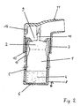
- Figs. 2 and 3 are preferred embodiments of an inventive one Applicator shown.
- the reference number (11) is the dispensing head with the cylindrical one Recording for the valve stem (10) of the metering valve, the Pressure vessel (1) with housing (5) correspond approximately to that shown in Fig. 1 Arrangement.
- the dispensing head (11) on the housing (5) supported.
- This type of holder has the particular advantage that the valve stem (10) of the metering valve (2) before mechanical stress and blockage is protected by dirt particles.
- the dispensing head (11) is advantageously connected to the housing (5) so firmly that that it cannot come loose on its own under normal use. So that is the applicator is ready for use at any time.
- Figures 2 and 3 are without limitation generally two different variants for such a connection demonstrated.
- the dispensing head (11) is attached to the housing (5) from above and anchored in this position.
- the dispensing head (11) has on its lower End inward hooks (12), which in corresponding grooves (13) engage in the housing wall.
- the grooves (13) have a longitudinal expansion, a vertical movement of the dispensing head (11) for actuating the Allow metering valve (2).
- the metering valve (2) is pressed down of the dispensing head (11) triggered, whereby a defined via the spray opening Amount of active ingredient is released. After administration, the Dispensing head (11) by the spring force of the metering valve (2) back to its starting position recycled.
- the dispensing head has on the back Ventilation openings (14), which are designed so that an unwanted Closing by the user is excluded.
- the dispensing head (11) is rigid connected to the housing (5), for example by means of ultrasonic welding.
- the metering valve (2) from below to the Activating device (15) acting on the bottom of the container is triggered.
- the pressure vessel (1) can be in the housing (5) moved vertically, thereby actuating the metering valve. So that Function of the system is guaranteed, the housing (5) must be opposite the embodiment shown in Fig. 2 by at least the length of the valve actuation path be extended.
- the activation device (15) consists of a finger rest (16) and a attached, in the housing (5) projecting web (17), which at the end has a thickening (18) whose diameter is larger than the diameter the implementation.
- the pressure vessel (1) sits with the bottom on the Activation device (15). The finger rest is used to administer the drug (16) pressed against the housing (5).
- the web presses (18) on the bottom of the pressure vessel (1) which is so up against moves the spring pressure of the metering valve (2) so that the cylindrical cannula (10) of the metering valve (2) against the cylindrical receptacle of the dispensing head (11) presses and the metering valve (2) triggers.
Landscapes
- Health & Medical Sciences (AREA)
- Engineering & Computer Science (AREA)
- Bioinformatics & Cheminformatics (AREA)
- Pulmonology (AREA)
- Anesthesiology (AREA)
- Biomedical Technology (AREA)
- Heart & Thoracic Surgery (AREA)
- Hematology (AREA)
- Life Sciences & Earth Sciences (AREA)
- Animal Behavior & Ethology (AREA)
- General Health & Medical Sciences (AREA)
- Public Health (AREA)
- Veterinary Medicine (AREA)
- Containers And Packaging Bodies Having A Special Means To Remove Contents (AREA)
- Details Of Rigid Or Semi-Rigid Containers (AREA)
Description
einen Abgabeknopf, welcher mit dem Abgabeorgan so zusammenwirkt, dass bei Pressen beider Teile gegeneinander das Abgabeorgan betätigt wird, und eine bestimmte Menge der wenigstens einen abzugebenden Substanz die Austrittsöffnung durchtritt und in Form wenigstens eines Strahls aus einer Sprühöffnung im Angabekopf ausgestoßen wird.
- σm =
- Mindestzugfestigkeit der Verbindung [MPa]
- da =
- Außendurchmesser des Hohlkörpers [mm]
- s =
- Wanddicke des Hohlkörpers [mm]
- Fig. 1
- einen Druckbehälter aus Glas mit Dosierventil für einen Applikator für Inhalationspräparate, der gemäß der Erfindung vollständig von einem selbsttragenden Gehäuse umgeben ist;
- Fig. 2
- eine bevorzugte Ausführungsform eines erfindungsgemäßen Applikators und
- Fig. 3
- eine weitere bevorzugte Ausführungsform eines erfindungsgemäßen Applikators.
Claims (11)
- Vorrichtung zur Verabreichung von Substanzen, insbesondere Inhalationspräparate (Aerosole), mit Überdruck, umfassend einen Druckbehälter (1) aus Glas, der wenigstens einen Vorrat einer abzugebenden Substanz und wenigstens eines Treibmittels enthält,
und der eine Austrittsöffnung (3) aufweist, auf der ein Abgabeorgan (2) befestigt ist,
einen Berst- und Splitterschutz aus Kunststoff (5), gebildet durch ein selbsttragendes Gehäuse (5) das den Druckbehälter (1) umgibt und das Abgabeorgan (2) mit Ausnahme der Austrittsöffnung (3) völlig umgreift, sowie Druckaustrittsöffnungen (8) im Gehäuse (5),
einen Abgabekopf (11), welcher mit dem Abgabeorgan (2) so zusammenwirkt, dass bei Pressen beider Teile gegeneinander das Abgabeorgan (2) betätigt wird, und eine bestimmte Menge der wenigstens einen abzugebenden Substanz die Austrittsöffnung (3) durchtritt und in Form wenigstens eines Strahls aus einer Sprühöffnung im Abgabekopf (11) ausgestoßen wird,
dadurch gekennzeichnet, dass der Berst- und Splitterschutz durch ein Gehäuse (5) gebildet wird, welches auf seiner Innenwandung mit einem Kanalsystem versehen ist, das so ausgebildet ist, dass im Berstfall des Druckbehälters (1) die abzugebende Substanz und/oder das Treibmittel durch die Kanäle unmittelbar zu den Druckaustrittsöffnungen (8) geführt werden und das Gehäuse (5) wenigstens in seinem unteren Bereich aus einem transparenten Kunststoff besteht. - Vorrichtung nach Anspruch 1,
dadurch gekennzeichnet, dass das Kanalsystem aus spiralförmig oder der Form eines quadratischen Musters auf der Innenwandung des Gehäuses (5) angeordneten Kanälen besteht. - Vorrichtung nach Anspruch 1.
dadurch gekennzeichnet, dass das Gehäuse (5) aus zwei miteinander verbindbaren Halbschalen (6, 7) besteht, wobei die untere Halbschale (6) aus einem transparenten Kunststoff besteht. - Vorrichtung nach Anspruch 3,
dadurch gekennzeichnet, dass die obere Halbschale (7) zur Kennzeichnung bestimmter Medikamente aus einem farbigen Kunststoff besteht oder eine farbige Markierung aufweist. - Vorrichtung nach Anspruch 3 oder 4,
dadurch gekennzeichnet, dass die beiden Halbschalen (6, 7) lösbar miteinander verbunden sind. - Vorrichtung nach Anspruch 5,
dadurch gekennzeichnet, dass die beiden Halbschalen (6, 7) mittels übereinander schiebbarer Widerhaken (12) miteinander verhakt sind. - Vorrichtung nach wenigstens einem der Ansprüche 1 - 6,
dadurch gekennzeichnet, dass der Abgabekopf (11) am Gehäuse (5) gehaltert ist. - Vorrichtung nach Anspruch 7,
dadurch gekennzeichnet, dass der Abgabekopf (11) fest mit dem Gehäuse (5) verbunden ist, und der Druckbehälter (1) zur Betätigung des Abgabeorganes (2) in dem Gehäuse (5) in Längsrichtung bewegbar ist. - Vorrichtung nach Anspruch 8,
dadurch gekennzeichnet, dass der Druckbehälter (1) mittels einer von unten auf den Behälterboden einwirkenden Aktivierungseinrichtung (15) in dem Gehäuse (5) bewegbar ist. - Vorrichtung nach Anspruch 7,
dadurch gekennzeichnet, dass der Druckbehälter (1) fest in dem Gehäuse (5) positioniert ist, und der Abgabekopf (11) zur Betätigung des Abgabeorganes (2) in Längsrichtung beweglich an dem Gehäuse (5) gehaltert ist. - Vorrichtung nach Anspruch 10,
dadurch gekennzeichnet, dass das Gehäuse (5) zur Führung und Halterung des Abgabekopfes (11) an seiner Außenseite sich in Längsrichtung erstreckenden Nuten (13) aufweist, in die entsprechend nach innen weisende Haken (12) am unteren Ende des Abgabekopfes (11) eingreifen.
Applications Claiming Priority (2)
| Application Number | Priority Date | Filing Date | Title |
|---|---|---|---|
| DE19525546 | 1995-07-13 | ||
| DE19525546A DE19525546C2 (de) | 1995-07-13 | 1995-07-13 | Vorrichtung zur Verabreichung von Substanzen, insbesondere Inhalationspräparate |
Publications (3)
| Publication Number | Publication Date |
|---|---|
| EP0753293A2 EP0753293A2 (de) | 1997-01-15 |
| EP0753293A3 EP0753293A3 (de) | 1997-12-29 |
| EP0753293B1 true EP0753293B1 (de) | 2003-05-28 |
Family
ID=7766740
Family Applications (1)
| Application Number | Title | Priority Date | Filing Date |
|---|---|---|---|
| EP96101748A Expired - Lifetime EP0753293B1 (de) | 1995-07-13 | 1996-02-07 | Vorrichtung zur Verabreichung von Substanzen, insbesondere Inhalationspräparate |
Country Status (4)
| Country | Link |
|---|---|
| US (1) | US5878917A (de) |
| EP (1) | EP0753293B1 (de) |
| JP (1) | JPH0928804A (de) |
| DE (2) | DE19525546C2 (de) |
Cited By (1)
| Publication number | Priority date | Publication date | Assignee | Title |
|---|---|---|---|---|
| US9179691B2 (en) | 2007-12-14 | 2015-11-10 | Aerodesigns, Inc. | Delivering aerosolizable food products |
Families Citing this family (23)
| Publication number | Priority date | Publication date | Assignee | Title |
|---|---|---|---|---|
| DE50001559D1 (de) * | 1999-05-25 | 2003-04-30 | Masanis Art Food & Fashion Ltd | Parfumdispenser |
| WO2001028887A1 (en) * | 1999-10-16 | 2001-04-26 | Glaxo Group Limited | Device housing for an aerosol container |
| PL204106B1 (pl) | 2000-02-28 | 2009-12-31 | Pharmakodex Ltd | Zestaw do dostarczania środka terapeutycznego |
| US6951215B1 (en) * | 2000-07-14 | 2005-10-04 | Tufts University | Drug delivery device for animals |
| US20040079361A1 (en) * | 2001-01-17 | 2004-04-29 | Clayton Colin D. | Medicinal aerosols |
| US6769572B1 (en) * | 2001-12-27 | 2004-08-03 | Anthony Cullotta | Custom color spray paint cans |
| AU2003212529B2 (en) * | 2002-03-22 | 2008-07-10 | Clinical Designs Limited | Can fixture |
| GB2398503A (en) | 2003-02-11 | 2004-08-25 | Bespak Plc | Inhaler with removable mouthpiece |
| GB0327112D0 (en) * | 2003-11-21 | 2003-12-24 | Clincial Designs Ltd | Dispenser and reservoir |
| DE202004007115U1 (de) * | 2004-05-03 | 2004-07-08 | Altana Pharma Ag | Blindungsvorrichtung |
| GB0425518D0 (en) * | 2004-11-19 | 2004-12-22 | Clinical Designs Ltd | Substance source |
| GB0428204D0 (en) * | 2004-12-23 | 2005-01-26 | Clinical Designs Ltd | Medicament container |
| US8087548B2 (en) * | 2008-05-14 | 2012-01-03 | S.C. Johnson & Son, Inc. | Spray products with particles and improved valve for inverted dispensing without clogging |
| GB0904059D0 (en) | 2009-03-10 | 2009-04-22 | Euro Celtique Sa | Counter |
| GB0904040D0 (en) | 2009-03-10 | 2009-04-22 | Euro Celtique Sa | Counter |
| WO2014089272A1 (en) * | 2012-12-06 | 2014-06-12 | Fusion Packaging I, LP | Dispenser with varying bottle majority and base cover |
| US9505015B2 (en) | 2013-05-21 | 2016-11-29 | S. C. Johnson & Son, Inc. | Trigger sprayer with bottle filling conduit |
| WO2017055786A1 (en) * | 2015-10-01 | 2017-04-06 | Presspart Manufacturing Limited | Metered dose inhaler canister and shroud |
| CN107878897B (zh) * | 2017-12-27 | 2024-09-24 | 洛阳明创矿山冶金设备有限公司 | 一种冶金用备件储存保护装置 |
| JP7015174B2 (ja) * | 2018-01-17 | 2022-02-02 | 日本製紙株式会社 | 液体用容器からの液体注出装置 |
| WO2019142813A1 (ja) * | 2018-01-17 | 2019-07-25 | 日本製紙株式会社 | 詰め替え容器 |
| US20220401663A1 (en) * | 2021-06-18 | 2022-12-22 | Loop Laboratories, LLC | Compact atomizer |
| CN117281984A (zh) * | 2021-12-27 | 2023-12-26 | 广州阜耀生物科技有限公司 | 一种抛射型气雾剂给用辅助设备及其使用方法 |
Family Cites Families (7)
| Publication number | Priority date | Publication date | Assignee | Title |
|---|---|---|---|---|
| USRE26304E (en) * | 1962-05-07 | 1967-11-21 | Aerosol dispensing package | |
| FR1476700A (fr) * | 1966-02-16 | 1967-04-14 | Quercia Flaminaire Sa | Perfectionnements apportés aux flacons de multirecharge d'un gaz liquéfié sous pression |
| US3968871A (en) * | 1975-05-16 | 1976-07-13 | Briscoe Woodrow H | Safety container for medicine bottles and the like |
| ATE109564T1 (de) * | 1988-01-25 | 1994-08-15 | Mallinckrodt Inc | Flüssigkeitsbehälter zur beobachtung von verunreinigungen. |
| GB9026191D0 (en) * | 1990-12-01 | 1991-01-16 | Harris Pharma Ltd | Breath actuated dispensing device |
| DE9113446U1 (de) * | 1991-10-29 | 1992-01-16 | Kendall Medizinische Erzeugnisse GmbH, 8425 Neustadt | Handvernebler für das Zerstäuben von therapeutischen Flüssigkeiten |
| DE29511334U1 (de) * | 1995-07-13 | 1995-12-14 | Schott Glaswerke, 55122 Mainz | Vorrichtung zur Verabreichung von Substanzen, insbesondere Inhalationspräparaten |
-
1995
- 1995-07-13 DE DE19525546A patent/DE19525546C2/de not_active Expired - Fee Related
-
1996
- 1996-02-07 DE DE59610469T patent/DE59610469D1/de not_active Expired - Fee Related
- 1996-02-07 EP EP96101748A patent/EP0753293B1/de not_active Expired - Lifetime
- 1996-07-12 US US08/678,857 patent/US5878917A/en not_active Expired - Fee Related
- 1996-07-12 JP JP8183209A patent/JPH0928804A/ja active Pending
Cited By (1)
| Publication number | Priority date | Publication date | Assignee | Title |
|---|---|---|---|---|
| US9179691B2 (en) | 2007-12-14 | 2015-11-10 | Aerodesigns, Inc. | Delivering aerosolizable food products |
Also Published As
| Publication number | Publication date |
|---|---|
| EP0753293A2 (de) | 1997-01-15 |
| EP0753293A3 (de) | 1997-12-29 |
| DE19525546C2 (de) | 2002-05-02 |
| JPH0928804A (ja) | 1997-02-04 |
| US5878917A (en) | 1999-03-09 |
| DE19525546A1 (de) | 1997-01-16 |
| DE59610469D1 (de) | 2003-07-03 |
Similar Documents
| Publication | Publication Date | Title |
|---|---|---|
| DE19525546C2 (de) | Vorrichtung zur Verabreichung von Substanzen, insbesondere Inhalationspräparate | |
| DE60221695T2 (de) | Durch inhalation aktivierte vorrichtung | |
| EP1474195B1 (de) | Inhalationshilfsgerät | |
| WO1997039831A1 (de) | Zweikammer-kartusche für treibgasfreie dosieraerosole | |
| DE2654019A1 (de) | Aerosolinhalator ii | |
| DE69411462T2 (de) | System zur Abgabe von dosierten Mengen von Flüssigkeiten, insbesondere von Arzneimitteln | |
| EP1539368B1 (de) | Gerät mit Blockiervorrichtung für ein Sperrspannwerk mit federbetätigtem Antrieb | |
| DE69001965T2 (de) | Aerosolspender. | |
| DE69210561T2 (de) | Dosierspender | |
| DE68906252T2 (de) | Aerosol-inhalationsgeraet. | |
| EP1321160A2 (de) | Verfahren und Spender zum Mischen und Austragen von Medien | |
| DE1566630B1 (de) | Geraet zur Abgabe dosierter Mengen eines medizinischen Wirkstoffs | |
| EP1219356A2 (de) | Austragvorrichtung für fliessfähige Medien mittels einer Schubkolbenpumpe | |
| DE69301974T2 (de) | Behälter zum spenden von flüssigkeiten | |
| DE2654018A1 (de) | Aerosolinhalator i | |
| EP1100474A2 (de) | Zweiteilige kapsel zur aufnahme von pharmazeutischen zubereitungen für pulverinhalatoren | |
| DE1491707A1 (de) | Vorrichtung fuer nasale Anwendung von Medikamenten | |
| WO2008006527A1 (de) | Vorrichtung zur dosierten abgabe von versprühbaren stoffen | |
| DE69628095T2 (de) | Gaszuführvorrichtung | |
| DD146891A5 (de) | Aerosolerzeugnis sowie verfahren und vorrichtung zu dessen herstellung | |
| EP0996478B1 (de) | Spraymechanismus für dosier-sprayflaschen | |
| DE29511334U1 (de) | Vorrichtung zur Verabreichung von Substanzen, insbesondere Inhalationspräparaten | |
| AT1175U1 (de) | Inhalationshilfsgerät | |
| EP0052161A1 (de) | Vorrichtung zum Ausgeben von gasförmigen, flüssigen oder pulverförmigen Stoffen | |
| DE3229702A1 (de) | Medizinisches inhalationsgeraet |
Legal Events
| Date | Code | Title | Description |
|---|---|---|---|
| PUAI | Public reference made under article 153(3) epc to a published international application that has entered the european phase |
Free format text: ORIGINAL CODE: 0009012 |
|
| 17P | Request for examination filed |
Effective date: 19960207 |
|
| AK | Designated contracting states |
Kind code of ref document: A2 Designated state(s): CH DE FR GB IT LI |
|
| PUAL | Search report despatched |
Free format text: ORIGINAL CODE: 0009013 |
|
| AK | Designated contracting states |
Kind code of ref document: A3 Designated state(s): CH DE FR GB IT LI |
|
| RAP1 | Party data changed (applicant data changed or rights of an application transferred) |
Owner name: CARL-ZEISS-STIFTUNG TRADING AS SCHOTT GLASWERKE Owner name: SCHOTT GLAS |
|
| RAP1 | Party data changed (applicant data changed or rights of an application transferred) |
Owner name: CARL-ZEISS-STIFTUNG TRADING AS SCHOTT GLAS Owner name: SCHOTT GLAS |
|
| 17Q | First examination report despatched |
Effective date: 20020408 |
|
| GRAH | Despatch of communication of intention to grant a patent |
Free format text: ORIGINAL CODE: EPIDOS IGRA |
|
| RIC1 | Information provided on ipc code assigned before grant |
Free format text: 7A 61M 15/00 A |
|
| GRAH | Despatch of communication of intention to grant a patent |
Free format text: ORIGINAL CODE: EPIDOS IGRA |
|
| GRAA | (expected) grant |
Free format text: ORIGINAL CODE: 0009210 |
|
| AK | Designated contracting states |
Designated state(s): CH DE FR GB IT LI |
|
| REG | Reference to a national code |
Ref country code: GB Ref legal event code: FG4D Free format text: NOT ENGLISH |
|
| REG | Reference to a national code |
Ref country code: CH Ref legal event code: EP |
|
| REF | Corresponds to: |
Ref document number: 59610469 Country of ref document: DE Date of ref document: 20030703 Kind code of ref document: P |
|
| GBT | Gb: translation of ep patent filed (gb section 77(6)(a)/1977) | ||
| ET | Fr: translation filed | ||
| PLBE | No opposition filed within time limit |
Free format text: ORIGINAL CODE: 0009261 |
|
| STAA | Information on the status of an ep patent application or granted ep patent |
Free format text: STATUS: NO OPPOSITION FILED WITHIN TIME LIMIT |
|
| 26N | No opposition filed |
Effective date: 20040302 |
|
| PGFP | Annual fee paid to national office [announced via postgrant information from national office to epo] |
Ref country code: FR Payment date: 20050218 Year of fee payment: 10 |
|
| PGFP | Annual fee paid to national office [announced via postgrant information from national office to epo] |
Ref country code: GB Payment date: 20050228 Year of fee payment: 10 |
|
| PGFP | Annual fee paid to national office [announced via postgrant information from national office to epo] |
Ref country code: CH Payment date: 20050324 Year of fee payment: 10 |
|
| PG25 | Lapsed in a contracting state [announced via postgrant information from national office to epo] |
Ref country code: GB Free format text: LAPSE BECAUSE OF NON-PAYMENT OF DUE FEES Effective date: 20060207 |
|
| PGFP | Annual fee paid to national office [announced via postgrant information from national office to epo] |
Ref country code: DE Payment date: 20060214 Year of fee payment: 11 |
|
| PG25 | Lapsed in a contracting state [announced via postgrant information from national office to epo] |
Ref country code: LI Free format text: LAPSE BECAUSE OF NON-PAYMENT OF DUE FEES Effective date: 20060228 Ref country code: CH Free format text: LAPSE BECAUSE OF NON-PAYMENT OF DUE FEES Effective date: 20060228 |
|
| PGFP | Annual fee paid to national office [announced via postgrant information from national office to epo] |
Ref country code: IT Payment date: 20060228 Year of fee payment: 11 |
|
| REG | Reference to a national code |
Ref country code: CH Ref legal event code: PL |
|
| GBPC | Gb: european patent ceased through non-payment of renewal fee |
Effective date: 20060207 |
|
| REG | Reference to a national code |
Ref country code: FR Ref legal event code: ST Effective date: 20061031 |
|
| PG25 | Lapsed in a contracting state [announced via postgrant information from national office to epo] |
Ref country code: FR Free format text: LAPSE BECAUSE OF NON-PAYMENT OF DUE FEES Effective date: 20060228 Ref country code: DE Free format text: LAPSE BECAUSE OF NON-PAYMENT OF DUE FEES Effective date: 20070901 |
|
| PG25 | Lapsed in a contracting state [announced via postgrant information from national office to epo] |
Ref country code: IT Free format text: LAPSE BECAUSE OF NON-PAYMENT OF DUE FEES Effective date: 20070207 |