EP0750098B1 - Brennkraftmaschine und Verfahren für Ventilsteuerung - Google Patents
Brennkraftmaschine und Verfahren für Ventilsteuerung Download PDFInfo
- Publication number
- EP0750098B1 EP0750098B1 EP96110075A EP96110075A EP0750098B1 EP 0750098 B1 EP0750098 B1 EP 0750098B1 EP 96110075 A EP96110075 A EP 96110075A EP 96110075 A EP96110075 A EP 96110075A EP 0750098 B1 EP0750098 B1 EP 0750098B1
- Authority
- EP
- European Patent Office
- Prior art keywords
- air intake
- exhaust
- valve
- rocker
- valves
- Prior art date
- Legal status (The legal status is an assumption and is not a legal conclusion. Google has not performed a legal analysis and makes no representation as to the accuracy of the status listed.)
- Expired - Lifetime
Links
- 238000002485 combustion reaction Methods 0.000 title claims description 32
- 238000000034 method Methods 0.000 title claims description 9
- 230000007246 mechanism Effects 0.000 claims description 29
- 230000005540 biological transmission Effects 0.000 claims description 28
- 210000001331 nose Anatomy 0.000 description 76
- 230000007704 transition Effects 0.000 description 11
- 238000010586 diagram Methods 0.000 description 10
- 230000014759 maintenance of location Effects 0.000 description 10
- 210000003128 head Anatomy 0.000 description 8
- 230000001133 acceleration Effects 0.000 description 6
- 230000009471 action Effects 0.000 description 5
- 230000004044 response Effects 0.000 description 5
- 239000000446 fuel Substances 0.000 description 3
- 230000000717 retained effect Effects 0.000 description 3
- 230000008859 change Effects 0.000 description 2
- 230000003292 diminished effect Effects 0.000 description 2
- 239000012530 fluid Substances 0.000 description 2
- 230000013011 mating Effects 0.000 description 2
- 230000004048 modification Effects 0.000 description 2
- 238000012986 modification Methods 0.000 description 2
- OKTJSMMVPCPJKN-UHFFFAOYSA-N Carbon Chemical compound [C] OKTJSMMVPCPJKN-UHFFFAOYSA-N 0.000 description 1
- 229910052799 carbon Inorganic materials 0.000 description 1
- 238000005266 casting Methods 0.000 description 1
- 238000010276 construction Methods 0.000 description 1
- 230000001419 dependent effect Effects 0.000 description 1
- 238000006073 displacement reaction Methods 0.000 description 1
- 230000000694 effects Effects 0.000 description 1
- 238000000638 solvent extraction Methods 0.000 description 1
- 230000000087 stabilizing effect Effects 0.000 description 1
- 230000001360 synchronised effect Effects 0.000 description 1
Images






Classifications
-
- F—MECHANICAL ENGINEERING; LIGHTING; HEATING; WEAPONS; BLASTING
- F01—MACHINES OR ENGINES IN GENERAL; ENGINE PLANTS IN GENERAL; STEAM ENGINES
- F01L—CYCLICALLY OPERATING VALVES FOR MACHINES OR ENGINES
- F01L1/00—Valve-gear or valve arrangements, e.g. lift-valve gear
- F01L1/12—Transmitting gear between valve drive and valve
- F01L1/18—Rocking arms or levers
- F01L1/185—Overhead end-pivot rocking arms
-
- F—MECHANICAL ENGINEERING; LIGHTING; HEATING; WEAPONS; BLASTING
- F01—MACHINES OR ENGINES IN GENERAL; ENGINE PLANTS IN GENERAL; STEAM ENGINES
- F01L—CYCLICALLY OPERATING VALVES FOR MACHINES OR ENGINES
- F01L1/00—Valve-gear or valve arrangements, e.g. lift-valve gear
- F01L1/26—Valve-gear or valve arrangements, e.g. lift-valve gear characterised by the provision of two or more valves operated simultaneously by same transmitting-gear; peculiar to machines or engines with more than two lift-valves per cylinder
- F01L1/265—Valve-gear or valve arrangements, e.g. lift-valve gear characterised by the provision of two or more valves operated simultaneously by same transmitting-gear; peculiar to machines or engines with more than two lift-valves per cylinder peculiar to machines or engines with three or more intake valves per cylinder
-
- F—MECHANICAL ENGINEERING; LIGHTING; HEATING; WEAPONS; BLASTING
- F01—MACHINES OR ENGINES IN GENERAL; ENGINE PLANTS IN GENERAL; STEAM ENGINES
- F01L—CYCLICALLY OPERATING VALVES FOR MACHINES OR ENGINES
- F01L1/00—Valve-gear or valve arrangements, e.g. lift-valve gear
- F01L1/26—Valve-gear or valve arrangements, e.g. lift-valve gear characterised by the provision of two or more valves operated simultaneously by same transmitting-gear; peculiar to machines or engines with more than two lift-valves per cylinder
- F01L1/267—Valve-gear or valve arrangements, e.g. lift-valve gear characterised by the provision of two or more valves operated simultaneously by same transmitting-gear; peculiar to machines or engines with more than two lift-valves per cylinder with means for varying the timing or the lift of the valves
-
- F—MECHANICAL ENGINEERING; LIGHTING; HEATING; WEAPONS; BLASTING
- F01—MACHINES OR ENGINES IN GENERAL; ENGINE PLANTS IN GENERAL; STEAM ENGINES
- F01L—CYCLICALLY OPERATING VALVES FOR MACHINES OR ENGINES
- F01L13/00—Modifications of valve-gear to facilitate reversing, braking, starting, changing compression ratio, or other specific operations
- F01L13/0005—Deactivating valves
-
- F—MECHANICAL ENGINEERING; LIGHTING; HEATING; WEAPONS; BLASTING
- F02—COMBUSTION ENGINES; HOT-GAS OR COMBUSTION-PRODUCT ENGINE PLANTS
- F02F—CYLINDERS, PISTONS OR CASINGS, FOR COMBUSTION ENGINES; ARRANGEMENTS OF SEALINGS IN COMBUSTION ENGINES
- F02F1/00—Cylinders; Cylinder heads
- F02F1/24—Cylinder heads
- F02F1/42—Shape or arrangement of intake or exhaust channels in cylinder heads
- F02F1/4214—Shape or arrangement of intake or exhaust channels in cylinder heads specially adapted for four or more valves per cylinder
- F02F1/4221—Shape or arrangement of intake or exhaust channels in cylinder heads specially adapted for four or more valves per cylinder particularly for three or more inlet valves
-
- F—MECHANICAL ENGINEERING; LIGHTING; HEATING; WEAPONS; BLASTING
- F01—MACHINES OR ENGINES IN GENERAL; ENGINE PLANTS IN GENERAL; STEAM ENGINES
- F01L—CYCLICALLY OPERATING VALVES FOR MACHINES OR ENGINES
- F01L1/00—Valve-gear or valve arrangements, e.g. lift-valve gear
- F01L1/02—Valve drive
- F01L1/04—Valve drive by means of cams, camshafts, cam discs, eccentrics or the like
- F01L1/047—Camshafts
- F01L1/053—Camshafts overhead type
- F01L2001/0537—Double overhead camshafts [DOHC]
-
- F—MECHANICAL ENGINEERING; LIGHTING; HEATING; WEAPONS; BLASTING
- F01—MACHINES OR ENGINES IN GENERAL; ENGINE PLANTS IN GENERAL; STEAM ENGINES
- F01L—CYCLICALLY OPERATING VALVES FOR MACHINES OR ENGINES
- F01L3/00—Lift-valve, i.e. cut-off apparatus with closure members having at least a component of their opening and closing motion perpendicular to the closing faces; Parts or accessories thereof
- F01L2003/25—Valve configurations in relation to engine
- F01L2003/251—Large number of valves, e.g. five or more
-
- F—MECHANICAL ENGINEERING; LIGHTING; HEATING; WEAPONS; BLASTING
- F02—COMBUSTION ENGINES; HOT-GAS OR COMBUSTION-PRODUCT ENGINE PLANTS
- F02B—INTERNAL-COMBUSTION PISTON ENGINES; COMBUSTION ENGINES IN GENERAL
- F02B2275/00—Other engines, components or details, not provided for in other groups of this subclass
- F02B2275/18—DOHC [Double overhead camshaft]
Definitions
- the present invention relates to an internal combustion engine according to the preamble of independent claim 1 and to a method for controlling the valve actuation of an internal combustion engine according to the preamble of independent claim 13.
- variable lift control type of dynamic valve apparatus is the swing arm type that was described in the prior art, for example in Japan Patent Application Disclosure Sho 60-243310 (1985).
- This conventional apparatus pivotally supports the swing arms at their base end and brings the valve shaft into contact with their front end, wherein each of said swing arms would be pushed and driven by a cam nose, a second pivot also is present between the first pivot and the cam nose on said swing arm, and said second pivot can be moved up or down by a hydraulic cylinder.
- a multi-cylinder internal combustion engine operable with at least one ineffective cylinder wherein the cylinders of the engine comprise respective an inlet and an exhaust valve.
- the inlet and exhaust valve are openable and closeable by a rocker arm driven by a first cam nose mounted on a camshaft. Otherwise in a light condition of the engine at least one cylinder is switched off due to the holding of the inlet and exhaust valve in a close position by the rocker arm driven by a second cam nose mounted next to the first cam nose on the camshaft wherein the rocker arm is in sliding contact with the first and second noses.
- US-A-4,515,121 relates to a valve driving control apparatus in an internal combustion engine, wherein said engine comprises a plurality of power cylinders each having a plurality of intake and exhaust reciprocating valves which are made operative or inoperative depending upon the load conditions of said engine. Said operative or inoperative condition of said valves is controlled by a valve driving apparatus, wherein a controlling fluid flow is applied in said valve driving apparatus by a de-energizer or energizer electromagnetic solenoid to make said valves inoperative or operative.
- EP-A-0 037 443 relates to a means for overriding a control means which controls intake and exhaust valves during operation of an engine to maintain said intake and exhaust valves closed, wherein said means uses fluid pressure and controlling members to engage said valves in a closed position.
- this objective is solved through a method for controlling the valve actuation of an internal combustion engine having the features of claim 13.
- said moving mechanism comprises sliders slidingly mounted on the exhaust and intake rocker shafts and being movable by a transmission pin guidable by respective drive slots formed in said exhaust end intake rocker shafts for pushing said rocker arms form a first position to a second position, a spring for urging said rocker arms back to the first position when said sliders are released from said rocker arms, and an actuator rotating said exhaust and intake rocker shafts to actuate said sliders.
- said internal combustion engine comprises three intake air valves and two exhaust valves symmetrically arranged to both sides of a plane containing a central axis of said cylinder, it is advantageous when at least said air intake valves arranged at both sides of said plane and at least one of said exhaust valves are operable by said moving mechanism.
- all exhaust and all intake valves are operable by said moving mechanism.
- the rotational movement of the cam nose is transmitted to the valve by the rocker arm; when the rocker arm is in the non-operational position, the rotational movement of the cam nose is transmitted directly to the valve, and it is possible to vary the amount of valve lift depending on the axial position of the rocker arm.
- the cam nose is composed of a high speed nose and a low speed nose, so that, when the rocker arm is positioned in the operational position, the rotational movement of the high speed nose is transmitted by the rocker arm to the valve, and when the rocker arm is in the non-operational position, the rotational movement of the cam nose is transmitted directly to the valve.
- the low speed nose and high speed nose and the amount of lift in the designs it is possible to variably control the valve lift and the opening and closing timing. In this case, by setting the low speed nose to have approximately zero lift, it is possible to shut down the valve when the rocker arm is placed in the non-operational position.
- the above described shifting system is installed for one of the exhaust valves and for the left and right side intake valves, and the foregoing low speed nose is shaped to virtually shut down the opening and closing operations of the valve. Accordingly, during low speed operations, one of the foregoing exhaust valves, and the left and right side air intake valves are virtually shut down, while only the remaining exhaust valve and the center air intake valves are operated. During mid-speed operations, either the foregoing left or right side air intake valve is shut down while both exhaust valves and two air intake valves are operated. Further, in high speed operating ranges, all the valves are operated, thereby making it possible to shut down valve operations in three stages according to the operating state of the engine.
- the transfer speed of the rocker arm from the non-operational position to the operational position is higher than the transfer speed in the reverse direction, during rapid acceleration, for example, the number of valves operating can be immediately increased, thereby improving acceleration response.
- the rotation of the inner rocker shaft to preferred embodiment causes the rocker arms to be shifted to the non-operational position by the drive surface of the inner rocker arm which drives it in the non-operational direction when rotated, and the retaining members on the outer rocker shaft retain the rocker arms in said non-operational position.
- the rocker arms are released from the foregoing retainer position by the return drive surface on the inner rocker shaft, and the foregoing holding force immediately returns the rocker arms to the operational position.
- Figures 1 - 10 will be used to explain a first embodiment of dynamic valve apparatus for engines according to the present invention.
- Figure 1 is a top view showing the cylinder head with the cover removed;
- Figures 2 and 3 are sectional views taken along lines II-II and III-III of Figure 1, respectively;
- Figure 4 is a side view of the cylinder head;
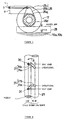
- Figure 5 is a diagram showing the shape of the cam nose;
- Figure 6 is a diagram showing the drive slot of the rocker shaft;
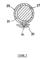
- Figure 7 is a sectional diagram of the rocker shaft drive mechanism,
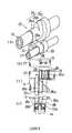
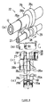
- Figures 8 through 10 are Figures that will be used to explain the operation.
- the exhaust side will be the front side and the air intake side will be the rear side, and left, right and center will refer to the directions when looking toward the front side from the rear side.
- 1 represents an engine cylinder head for a water-cooled, four-stroke cycle, in-line, twin cylinder, five-valve engine equipped with an embodiment of this invention, and it is secured to the top of the top mating surface of a cylinder body 2 that is affixed to the top of a crank case (not shown) by means of head bolts 3.
- Two concave combustion zones 1b are formed in the cylinder body mating surface 1a of the foregoing cylinder head 1, which, together with the cylinder bores 2a in the foregoing cylinder body 2, form the combustion chambers.
- Formed in said combustion areas 1 b are left and right side air intake valve openings 4a, 4b, a center air intake valve opening 4c, as well as left and right side exhaust valve openings 5a, 5.
- the foregoing air intake valve openings 4a - 4c converge into a single air intake port 4 which connecting them to the rear wall of the cylinder head 1.
- the foregoing exhaust valve openings 5a, 5b converge into a single exhaust port 5 connecting them to the front wall of said cylinder head 1.
- valve heads 7d of the air intake valves 7a, 7b and 7c are positioned, respectively, where they can open and close the foregoing air intake valve openings 4a - 4c.
- Valve springs 9, which hold the foregoing air intake valves 7a - 7c in the normally closed position, are located between a retainer 8 on the top surface of the valve shafts 7e and spring seats 1c formed in the cylinder head.
- Attached to the top ends of the foregoing air intake valves 7a - 7c are air intake lifters 10a. Said lifters 10a can freely slide in lifter guide holes 1d formed in the cylinder head 1.
- valve heads 11c of the left and right side exhaust valves 11a, 11b are positioned, respectively, where they can open and close the foregoing exhaust valve openings 5a, 5b.
- Valve springs 9, which hold the foregoing exhaust valves 11a, 11b in the normally closed position, are located between a retainer 8 on the top surface of the valve shafts 11d and spring seats 1c that were formed in the cylinder head 1.
- Attached to the top ends of the foregoing exhaust valves 11a, 11b are exhaust lifters 10b. Said lifters 10b can freely slide in lifter guide holes 1d formed in the cylinder head 1.
- An air intake camshaft 12 and exhaust camshaft 13 are installed in parallel above the foregoing air intake lifters 10a and exhaust lifters 10b. Said air intake and exhaust camshafts 12, 13 are axially supported by air intake and exhaust center bearings 14, 15 which are located in the areas of the shafts opposite the cylinder bore axes.
- the foregoing center exhaust bearings 15 are composed of receiver members 15a formed in the cylinder head 1 and of removable cam caps (not shown) attached thereto. Said cam caps are retained in place over the foregoing head receiver members 15a by cap bolts secured in two threaded bolt holes 15b.
- the foregoing center air intake bearings 14 are composed of receiver members 14a formed in the cylinder head 1 and of removable cam caps (not shown) attached thereto.
- the foregoing head side receiver member 14a splits left and right, on either side of the air intake lifter 10a, to accommodate the center air intake valve 7c. Further, said cam caps are forked and are retained in place over the foregoing head receiver members 14a by cap bolts secured in three threaded bolt holes 14b.
- the foregoing air intake and exhaust camshafts 12, 13 are supported on their right ends by the end bearings 16.
- Said end bearings 16 are composed of a head-side bearing 16a that is formed in the partitioning wall 1f between the cam chamber and the chain chamber 1e and the cover bearing (not shown) formed on one side of the head cover.
- Located inside the foregoing chain chamber are cam sprockets 17, 18 formed on the right ends of the foregoing camshafts 12, 13, respectively, and said sprockets 17, 18 are linked to the cam sprocket on the crankshaft by means of a timing chain 19.
- a variable exhaust timing mechanism 20 on the foregoing left side exhaust valve 11a and a fixed exhaust timing mechanism 21 on the right side exhaust valve 11b drive the valves open and closed, respectively. Further, a variable air intake timing mechanism 22 on the foregoing left and right side air intake valves 7a, 7b, and a fixed air intake timing mechanism 23 on the center air intakes valves drive them open and closed, respectively.
- the left and right side exhaust valves 11a, 11b are the same length.
- the foregoing fixed air intake timing mechanism 23 has a conventional structure.
- a center cam nose 12a formed on the air intake camshaft 12 directly drives the air intake lifter 10a to open and close the air intake valve 7.
- the fixed exhaust timing mechanism 20 has a right exhaust rocker arm 24 between the right side cam nose 13a formed on the exhaust camshaft and exhaust lifter 10b for the right side exhaust valve.
- This right side rocker arm 24 runs parallel to the exhaust camshaft at the front side of the exhaust lifter 10b and moreover it is slidably supported by the exhaust rocker shaft 25 which rotatably passes through it.
- variable exhaust timing mechanism 20 of the foregoing right side exhaust valve 11a and the variable air intake timing mechanism 22 for the left and right side air intake valves 7a, 7b are of the same basic structure except for the symmetrical positioning of their respective drive slots which will be described below. Accordingly, the following explanation will concern the variable air intake timing mechanism 22 for the left side air intake valve 7a.
- variable air intake timing mechanism 22 is structured so that the side cam nose 26 on the air intake camshaft 12 corresponding to the left side air intake valve 7a is shaped in a manner such that the side air intake lifter can be directly driven or be driven by means of the rocker arm 28.
- the foregoing side cam nose 26 is composed of a guide circle 26a which is of slightly greater diameter than the casting skin area 26d of the camshaft, of a high speed nose 26b which is of the same diameter of the base circle but has a lift amount a appropriate for the opening timing (operating angle) during high speed operations, and a of low speed nose 26c which has lift c and which has a base circle diameter that is slightly greater by the dimension b (1 mm or less) than that of said high speed nose 26b.
- the approximate center of the foregoing air intake lifter 10a is between the foregoing guide circle 26a and the low speed nose 26c.
- the air intake rocker shaft 27 rotatably passes through the rear side of the foregoing air intake lifter 10a and it runs parallel to the camshaft 12.
- left and right drive slots 31, 31' In the areas on this air intake rocker shaft 27 corresponding to the left and right air intake lifters 10a, 10a, as will be described further below, are left and right drive slots 31, 31', and there are a left drive slot 31 and a left side right drive slot 31' for the left side air intake valve which is shaped differently than that for the right drive slot 31'.
- annular left and right sliders 29 that can slide in the axial direction.
- Each of the sliders 29 has a transmission pin 30 that projects radially.
- the inside ends of said pins 30 are held in the foregoing drive slots 31, 31', and the outside ends are held in guide holes 1h formed parallel to the rocker shaft in the cylinder head 1.
- the foregoing left drive slots 31, 31' are composed of a slot area 31a that slants to the axial line of the rocker shaft, and a retention area 31b which is at right angles to the axial line of the rocker shaft, as is shown in Figure 6. Accordingly, when the rocker shaft 27 is rotated in the direction of arrow a shown in Figure 6, during the first half of the rotation, the foregoing transmission pin 30 moves in the left drive slots toward the cylindrical axis, but it does not move further during the second half. On the other hand, on the drive slot 31 side, there is no movement during the first half, but during the second half of the rotation there is movement toward the cylinder axis.
- the structure for the rocker shaft 25 drive slot on the exhaust side is similar to that of the foregoing left side drive slot 31, the first half of the rotation of the rocker arm causes the slider to move but will be held stationary through the second half of the rotation.
- rocker arm 28 Attached to the foregoing rocker shaft 27 is the above-mentioned rocker arm 28, which is in contact with the end surface of the foregoing slider 29, and said rocker arm 28 is free to slide and to move in the axial direction.
- a spring 32 held by a spring receiver 32a in contact with the anti-slider end surface of said rocker arm 28, and the other end of the spring is in held by a spring receiver 32a in the support boss 1g formed in the cylinder head 1. In this manner, the rocker arm 28 is normally held on the side of the high speed nose 26b.
- the rocker arm 28 with the foregoing structure follows the movement of the foregoing slider 29; when said rocker arm 28 is positioned farther away from the cylindrical axis by the slider 29, then it lies between the foregoing guide circle 26a and the lifter 10a (in the non-operational position), and when it is positioned closer to the cylindrical bore (the inside end) it lies between the foregoing high speed cam nose 26b and the lifter 10 (the operational position).
- a pinion unit 25b, 27b formed on the left ends of the foregoing exhaust and air intake rocker shafts 25, 27, and these pinion units engage a rack unit formed on the output shaft of a hydraulic actuator that is located in the left end of the cam chamber.
- a control signal is fed into a switching oil pressure valve in an oil pressure circuit for the foregoing hydraulic actuator 33 by an ECU (not shown).
- the control will be described in detail for the valve shutdown control, variable valve opening and closing timing, and variable valve lift control.
- the foregoing ECU functions as a positioning means for the rocker arms in this invention.
- the air intake and exhaust rocker shafts 25, 27 are held in the low speed position, and the transmission pins 30 on the sliders 29 lie in the low speed position (the outside end) in the various drive slots 31, 31', to position the sliders toward the outside. Accordingly, the rocker arm 28 lies in the non-operational position between the guide circle 26a and the lifter 10a. As a result, the rocker arm 28 does not swing, and the low speed cam nose 26c directly drives the lifter 10a. Accordingly, the left side exhaust valve 11a and the left and right side air intake valves 7a, 7b are lifted only slightly by the low speed cam nose 26c to a lift height c which keeps the valves virtually in a shutdown condition.
- the center air intake valve is always opened and closed at a fixed timing and lifts according to the nose shape and nose height of the center cam nose 12a which opens and closes the center air intake valve opening no matter what the engine RPM range, while the exhaust rocker arm 24, based upon its rocker ratio, opens and closes the right side exhaust valve opening 5b at a fixed timing and lift.
- the transmission pins 30 are moved axially in the drive slot 31 for the foregoing left side exhaust valve 11a and the left side air intake valve 7a to advance their rocker arms 28 to between the high speed nose 26b and the lifter 10a or 10b, thereby driving the left side exhaust valve 11a and the left side air intake valve 7a opened and closed by means of the high speed cam nose 26b and the rocker arms 28.
- the two exhaust valves, and two of the air intake valves are operating, while one air intake valve is shut down.
- the rocker shaft 27 When a transition is made from mid-speed to high speed operations, the rocker shaft 27 is rotated to its high speed position and the rocker pins 30 move to the high speed positions in the drive slots 31, 31'. In this case, the transmission pins 30 for the left side exhaust valve and the left side air intake valve do not move. On the other hand, the transmission pin for the right side air intake valve moves toward the inside in the drive area 31a of the drive slot 31', thereby causing the right side air intake valve 7b to begin operating. As a result, all the valves are operational.
- the transition is made from all the valves being operational to shutting down one of the air intake valves, followed by a condition where two of the air intake valves and one of the exhaust valves are shut down.
- Making the transition from operational to shutdown occurs by rotating the rocker shafts 25, 27 in the reverse direction as described above.
- the sliders 29 directly slide the rocker arm 28 from the position shown in Figure 10 to the position shown in Figure 9 or Figure 8 without respect to the angular position of the camshaft.
- the rocker arm 28 can be advanced into an operational position between the high speed cam nose 26c and the lifter 10a or withdrawn into the non-operational position, thereby making it possible to shut down two air intake valves and one exhaust valve during low speed operations, and to shut down one exhaust valve during mid-speed operations, thereby shutting down valves on the basis of the operating state of the engine.
- the low speed cam nose 26c has but a slight nose height c , even when the foregoing valves are in a shutdown period, the foregoing valves 11a, 7a, and 7b are opening and closing slightly, eliminating the possibility of fuel remaining in the vicinity of the valve opening and preventing the buildup of carbon and other deposits in the area of the exhaust valve opening.
- the rocker arm in the case where the structure is such that the rocker arms are directly moved by the rocker shaft without using any springs, the rocker arm must move at the point when the rocker's side surface is positioned at the base circle of the cam nose.
- the valve opening timing for each of the cylinders is different, and it would usually be impossible to set the timing for the rocker arms of all four cylinders to move to the base circle of the cam nose at the same time.
- it is difficult to adopt a direct moving structure for the rocker arms although it would be possible for a single-cylinder engine, and even possible for two-cylinder engines if the movement could be set between the combustion intervals.
- the present embodiment uses a guide circle 26a which is formed to the same diameter as the base circle of the high speed cam nose 26b, there can be a smooth transition from the shutdown position of the rocker arm 28 to the operational position. Even if the guide circle 26a is designed to be of somewhat larger diameter (10 ⁇ m for example) than the base circle of the high speed nose 26b, there is almost no impediment to the foregoing transition.
- the present embodiment continues the normal operation of the center air intake valve 7c while two of the three air intake valves are shut down, and because the left and right side exhaust valves 7a, 7b are shut down and put on variable timing, not only is it easy to secure the space required for said shifting mechanism, but in addition, since the center air intake valve 7c is the only valve imparting direction to the air intake during low speed operations, which directs it in the axial direction of the cylinder, the resulting tumbling action stabilizes lean combustion.
- While the foregoing first embodiment allows one air intake valve to operate during low speed operations, two to operate during mid-speed operations and three to operate during high-speed operations, it is possible to select the number of operating valves by the shape of the foregoing drive slots 31, 31'.
- the present embodiment uses a nose of 1 mm or less for the low speed nose 26c that virtually shuts down the valve, it is of course possible to employ any nose shape and height appropriate to low speed operations for said low speed nose 26c, thereby allowing different opening and closing timing and lift between low speed operations and mid-/high speed operations.
- the rocker arms are shifted between an operational position between the high speed nose and the lifter, and a non-operational position outside that position, and the freedom in design of the shape of the nose can be further broadened by using a structure that makes the rocker arm slidable between a high speed nose and a lifter and between a low speed nose and a lifter.
- Figures 11 and 12 show an example where the center air intake valve 7c is driven by a rocker arm 28'.
- the center bearing 14' composed of the bearing 15a formed in the head and the cam cap, has been divided into two parts which sandwich, on the left and right sides, the air intake lifter 10a, and a center rocker arm 28' is positioned between the left and right sections.
- the foregoing head cap is removably held in place by four bolts that thread into the head side bearings 14a.
- the engine used in this second embodiment is the same engine used in the foregoing first embodiment, and the basic structure of the dynamic valve apparatus is the same as that of the first embodiment, except that the rocker shafts have a double walled pipe structure composed of an inner rocker shaft and outer rocker shaft.
- the inner rocker shaft 41 on the air intake side is rotatably and axially supported by the support boss 1g and the center bearings 14, but it is incapable of movement in the axial direction. It can be rotated by means of the actuator 33.
- An outer rocker shaft 42 is installed coaxially around the outside circumference of the foregoing inner rocker shaft 41 and is rotatable with respect to it.
- the ends of said outer rocker shaft 42 are in contact with the foregoing support boss 1g and with the end surface of the center bearing 14 and it cannot move in the axial direction.
- Left and right drive slots 43, 44 are formed in the areas of the foregoing inner rocker shaft 41 and outer rocker shaft 42 that correspond to the left and right side air intake valves, as shown in Figure 14.
- Said left drive slot 43 is composed of inner and outer left drive slots 45,46 formed in the inner and outer rocker shafts 41, 42, respectively.
- the right drive slot 44 is composed of the inner and outer right drive slots 47 and 48 formed in the inner and outer rocker shafts 41, 42, respectively.
- the foregoing inner left drive slot 45 is composed of: a holding slot 45a, which extends at right angles (in the circumferential direction) with respect to the axial line a of the rocker shaft to form the operational position holding slot which holds the foregoing transmission pin 30 and the slider in the operational position; a non-operational direction angular drive surface 45b that continues from said operational position retention slot 45a and runs at an angle with respect to the rocker shaft axis a , and which, in conjunction with the rotation of said inner rocker shaft 41, causes the slider to move to the non-operational position; and a return drive surface 45c, which is formed parallel to the rocker shaft axis a , continuing from the foregoing operational position slot 45a, so that the slider can return from the above described non-operational position to the operational position without rotating the inner rocker shaft 41.
- outer left drive slot 46 has a non-operational position retention slot 46a which holds the foregoing slider in the non-operational position, and a guide slot 46 b, which extends in parallel to the rocker shaft axis a and which guides the movement of the foregoing slider 29 between the operational and non-operational positions.
- the foregoing inner right drive slot 47 is composed of: a non operational direction angular drive surface 47a, which is formed at an angle with respect to the rocker shaft axis a , and which with the rotation of the inner rocker shaft 41 causes the foregoing slider to move to the non-operational position; and a return drive surface 47b which is formed parallel to the rocker shaft axis and which, without the rotation of the inner rocker shaft 41, allows the slider 29 to return from the foregoing non-operational position to the operational position.
- the foregoing outer right drive slot 48 has a non-operational position retaining slot 48a that extends perpendicularly with respect to the rocker shaft axis a and which holds the foregoing slider in the non-operational position, and a guide slot 48b which extends in parallel to the rocker shaft axis.
- the exhaust rocker shaft is composed of an inner rocker shaft 52 which can be rotated by the foregoing actuator 33, and an outer rocker shaft 52, which can rotate with respect to the inner rocker shaft 51 but which cannot move axially.
- an inner drive slot and outer drive slot are formed in both of said rocker shafts 51, 52.
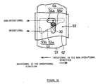
- Said inner drive slot 53 is formed at an angle with respect to the rocker shaft axis and it has a non-operational direction slanted drive surface 53a that drives the foregoing slider 29 to the non-operational position and a return drive surface 53b that is formed parallel to the rocker axis.
- the foregoing outer drive slot 54 has a non-operational position retention slot which retains the foregoing slider in the non-operational position, and a guide slot which runs parallel to the rocker shaft and which guides the movement of the foregoing slider between the operational and non-operation positions, parallel to the rocker shaft.
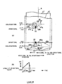
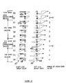
- the inner rocker shaft is at the right side position (the high speed operating position), and the transmission pins 30, in other words, the sliders 29, are positioned in the inner left and right drive slots 45, 47 in the left edge of the Figure, as well as in the left and right outer drive slots in the lower part of the Figure.
- the left side air intake valve becomes operational immediately ( Figure 15, (d), (e)).
- the center air intake valve 7c and the left side air intake valve 7a are operating, while the right side air intake valve 7b remains virtually shut down.
- the inner rocker shaft 41 is rotated to the mid-speed operation holding position as shown in Figure 16 in steps (f) - (i)
- the latter valve remains holding in that position.
- the transmission pin 30 for the right side air intake valve is in contact with the return drive surface 47b of the inner right drive slot 47, and it is held in this position.
- the inner rocker shafts 41, 51 when the air intake valve(s) and exhaust valve are shut down (to a non-operational state) from an operating state, the inner rocker shafts 41, 51 must be rotated through the entire angular length of the slanted drive surfaces 45b, 47a, and 53a, but on the other hand, when making a transition from a shutdown state to an operational state, the inner rocker shafts 41, 51 need only to be slightly rotated, thereby making the switch from a shutdown state to an operational state instantaneous.
- the time when the rocker arms can be moved axially into the operating position is restricted to the time interval when the base circle of the high speed cam 26b is positioned on the rocker arm side, and the higher the RPM, the shorter this interval.
- the present embodiment requires but a short interval for switching to the operational position, it is advantageous from this perspective as well.
- the present embodiment further sets the engine RPM at which switching is made to the non-operational state to be lower than that at which switching is made to the operational state.
- the left and right side air intake valves were shut down during low-speed operations, and one was returned to the operational state during mid-speed operations, and the remainder was rendered operational in the high speed operating range, thereby achieving valve shut down in stages, but the invention may also be applied of course to the shutting down and restorations of a single valve, or, a plurality of valves may be shut down at one time.
- the rotational movement of the cam nose is transmitted to the valves by the rocker arms, and when they are in the non-operational position, the valves are operated directly by the rotational movement of the cam nose, thereby allowing variable control of valve lift based upon the axial position of the rocker arms.
- the cam nose of a high speed nose and a low speed nose by constituting the cam nose of a high speed nose and a low speed nose, by putting the rocker arm into the operational position so that the rotational movement of the high speed cam nose is transmitted to the valve by the rocker arm, and by directly transmitting the rotational movement of the low speed cam nose to the valves when the rocker arm is in the non-operational position, it is possible to vary the amount of lift and the opening and closing timing according to the nose shapes of the low speed nose and the high speed nose and according to the lift height. Further, by setting the lift of the low speed nose to approximately zero, it is possible to place valves into a shutdown state using a very simple structure.
- the foregoing variation apparatus on one of the exhaust valves and upon the left and right side air intake valves, and by setting the foregoing low speed nose shape to virtually shut down the opening and closing operation, it is possible during low speed engine operations, to virtually shut down one of the foregoing exhaust valves, and the left and right side air intake valves and leave the other exhaust valve and the center valve operational, and, during mid-speed engine operations, it is possible to shut down the right or the left side air intake valve and leave the other two, as well as the two exhaust valves operational, and further, during high speed engine operations,-to have all the valves operational, thereby achieving a three-stage valve shutdown control that corresponds to the operating state of the engine.
- the air entering the cylinders is directed in the axial direction of the cylinders to generate a tumbling action, which is effective in stabilizing the combustion at lean air/fuel ratios.
- the rocker arms since on the one hand the amount of rotation of the inner rocker shaft causes a proportional movement of the rocker arm from the operational position to the non-operational position, while on the other, the rocker arms may be moved from the non-operational to the operational position without the rotation of the inner rocker shaft, it is possible to make a speedier transition in moving the rocker arm from the non-operational to the operational position than is in the reverse direction.
Landscapes
- Engineering & Computer Science (AREA)
- Mechanical Engineering (AREA)
- General Engineering & Computer Science (AREA)
- Chemical & Material Sciences (AREA)
- Combustion & Propulsion (AREA)
- Valve-Gear Or Valve Arrangements (AREA)
- Valve Device For Special Equipments (AREA)
Claims (16)
- Brennkraftmaschine mit einem Zylinderkörper (2), der zumindest einen Zylinder (2a) hat, einem Zylinderkopf (1), versehen mit jeweils einer Mehrzahl von Lufteinlaß- und Auslassventilen (7a - 7c; 11a; 11b), betätigbar über Lufteinlaß- und Luft-auslaßnockenwellen (12, 13) im Zusammenwirken mit jeweiligen Unterbrecherhebeln (28), montiert an jeweiligen Auslaß- und Einlassunterbrecherwellen (25, 27) und verbunden mit dem Zylinder (2a), und einer dynamischen Ventilvorrichtung (20, 22), die in der Lage ist, den Ventilöffnungs- und - schließzeitpunkt, den Ventilhub, und das Abschalten von zumindest einigen der Lufteinlaß- oder Auslassventile (7a, 11a) veränderbar zu steuern, dadurch gekennzeichnet, daß die dynamische Ventilvorrichtung (20, 22) mit einer Bewegungsvorrichtung (29 - 33) zum Bewegen der jeweiligen Unterbrecherhebel (28), zwischen einer Betriebsposition, in der eine Nockennase (26) jeder der Nockenwellen (12, 13) in Gleitkontakt mit den Unterbrecherhebeln (28) ist und einer Nichtbetriebsposition, in der der Unterbrecherhebel (28) der Nockennase (26) in axialer Richtung der Auslaß- und Einlassunterbrecherwellen (25, 27) versetzt ist, in Übereinstimmung mit den erfassten Motorbetriebsbedingungen, wobei die Bewegungsvorrichtung (29 - 33) vorgesehen ist, zumindest eines der Lufteinlassventile(7a, 7b), vorgesehen zu beiden Seiten einer Ebene, die eine Mittelachse des Zylinders (2a) und ein Mittel- Einlassventil (7c), das ständig betreibbar ist, enthält, und zumindest eines der Auslassventile (11a, 11b), zu betätigen.
- Brennkraftmaschine nach Anspruch 1, dadurch gekennzeichnet, dass der Nokken (26) einen Führungskreis (26a) aufweist, eingreifbar durch den Unterbrecherhebel (28) und der die Nichtbetriebsposition bildet und eine Hochdrehzahlnase (26b), ergreifbar durch den Unterbrecherhebel (28) und der die Betriebsposition bildet.
- Brennkraftmaschine nach Anspruch 1 oder 2, dadurch gekennzeichnet, dass der Nocken (26) außerdem eine Niedrigdrehzahlnase (26c) aufweist, die das jeweilige Lufteinlassventil (7a) oder Auslaßventil (11a) jeweils berührt, wenn der Unterbrecherhebel (28) in der Nichtbetriebsposition ist.
- Brennkraftmaschine nach Anspruch 3, dadurch gekennzeichnet, dass die Niedrigdrehzahlnase (26c) einen größeren Drehdurchmesser als die Hochdrehzahlnase (26b) hat.
- Brennkraftmaschine nach zumindest einem der Ansprüche 1 bis 4, dadurch gekennzeichnet, dass die Bewegungsvorrichtung Gleiter (29) aufweist, die gleitend auf den Auslaß- und Einlassunterbrecherwellen (25, 27) montiert sind und die durch einen Übertragungsbolzen (30) beweglich sind, führbar durch jeweilige Antriebsschlitze (31, 31'), die in den Auslaß- und Einlassunterbrecherwellen (25, 27) gebildet sind, um die Unterbrecherhebel (28) von einer ersten Position zu einer zweiten Position zu drücken, eine Feder (32) zum Zurückdrücken der Unterbrecherhebel (28) in die erste Position, wenn die Gleiter (29) von den Unterbrecherhebeln (28) freigegeben sind, und einen Betätiger (33), der die Auslaß- und Einlassunterbrecherwellen (25, 27) dreht, um die Gleiter (29) zu betätigen.
- Brennkraftmaschine nach zumindest einem der Ansprüche 1 bis 5, dadurch gekennzeichnet, dass drei Lufteinlassventile (7a - 7c) und zwei Auslassventile (11a, 11b) symmetrisch zu beiden Seiten der Ebene, die die Mittelachse des Zylinders (2a) enthält, angeordnet sind.
- Brennkraftmaschine nach Anspruch 6, dadurch gekennzeichnet, dass die Bewegungsvorrichtung (29 - 33) in der Lage ist, die jeweiligen Unterbrecherhebel (28) der zwei Lufteinlassventile (7a - 7c) und des einen Auslassventiles (11a, 11b) in die Nichtbetriebsposition in einem Niedrigdrehzahlzustand des Motors zu bewegen.
- Brennkraftmaschine nach Anspruch 7, dadurch gekennzeichnet, dass während eines mittleren Drehzahlzustandes des Motors nur ein Lufteinlaßventil (7a - 7c) in die Nichtbetriebsposition bewegbar ist.
- Brennkraftmaschine nach zumindest einem der Ansprüche 1 bis 8, dadurch gekennzeichnet, dass die Bewegungsvorrichtung (29 - 33) in der Lage ist, die jeweiligen Unterbrecherhebel (28) von der Nichtbetriebsposition mit einer höheren Drehzahl als von der Betriebsposition in die Nichtbetriebsposition zu bewegen.
- Brennkraftmaschine nach zumindest einem der Ansprüche 1 bis 9, dadurch gekennzeichnet, dass die Bewegungsvorrichtung (29 - 33) durch eine Motorsteuereinheit (ECU) steuerbar ist.
- Brennkraftmaschine nach zumindest einem der Ansprüche 5 bis 10, dadurch gekennzeichnet, dass die Bewegungsvorrichtung (29, 30, 32, 33) außerdem aufweist innere Unterbrecherwellen (41, 51), versehen mit jeweiligen inneren Antriebsschlitzen (45, 47,53), äußere Unterbrecherwellen (42, 52), koaxial ausgerichtet mit den inneren Unterbrecherwellen (41, 51) und versehen mit jeweiligen äußeren Antriebsschlitzen (46, 48, 54) in solch einer Weise, dass sie in Bezug zueinander drehbar sind.
- Brennkraftmaschine nach zumindest einem der Ansprüche 6 bis 11, dadurch gekennzeichnet, dass alle Auslaß- und Einlassventile (11a, 11b, 7a - 7c) durch die Bewegungsvorrichtungen (29 - 33) betätigbar sind.
- Verfahren zum Steuern der Ventilbetätigung einer Brennkraftmaschine mit einem Zylinderkörper (2), der zumindest eine Zylinder (2a) hat, einem Zylinderkopf (1), versehen mit einer Mehrzahl von Einlaß- und Auslassventilen (7a, 11a), betätigbar über Lufteinlaß- und Luftauslassnockenwellen (12, 13) im Zusammenwirken mit jeweiligen Unterbrecherhebeln (28), montiert an jeweiligen Auslaß- und Einlassunterbrecherwellen (25, 27) und verbunden mit dem Zylinder (2a), und einer dynamischen Ventilvorrichtung (20, 22), die in der Lage ist, den Ventilöffnungs- oder -schließzeitpunkt, den Ventilhub, und das Abschalten von zumindest einigen der Lufteinlaß- oder Auslassventile (7a, 11a) veränderbar zu steuern, gekennzeichnet durch die Schritte des Bewegens der Unterbrecherhebel (28) mittels der dynamischen Ventilvorrichtung (20, 22), die eine Bewegungsvorrichtung (29 - 33) hat, zwischen einer Betriebsposition, in der eine Nockennase (26) jeder der Nockenwellen (12, 13) in Gleitkontakt mit dem Unterbrecherhebel (28) ist und einer Nichtbetriebsposition, in der der Unterbrecherhebel (218) der Nockennase (26) in axialer Richtung der Auslaß- und Einlassunterbrecherwellen (25, 27) versetzt ist, in Übereinstimmung mit den erfassten Motorbetriebsbedingungen, wobei zumindest eines der Luftelnlassventile(7a, 7b), vorgesehen zu beiden Seiten einer Ebene, die eine Mittelachse des Zylinders (2a) und ein Mittel- Einlassventil (7c), das ständig betreibbar ist, enthält, und zumindest eines der Auslassventile (11a, 11b) durch die Bewegungsvorrichtung (29 - 33) betätigt werden.
- Verfahren nach Anspruch 13, dadurch gekennzeichnet, dass während eines Niedrigdrehzahlzustandes des Motors die zwei Luft- Einlassventile (7a - 7c) und das eine Auslaßventil (11a, 11b) in den Nichtbetriebszustand bewegt werden.
- Verfahren nach dem Anspruch 13 oder 14, dadurch gekennzeichnet, dass in einem mittleren Drehzahlzustand des Motors nur ein Lufteinlassventil (7a - 7c) in den Nichtbetriebszustand bewegt wird.
- Verfahren nach zumindest einem der Ansprüche 13 bis 15, dadurch gekennzeichnet, dass eine Motorsteuereinheit (ECU) die Bewegungsvorrichtung (29 - 33) steuert.
Applications Claiming Priority (3)
| Application Number | Priority Date | Filing Date | Title |
|---|---|---|---|
| JP15603795A JP3402853B2 (ja) | 1995-04-12 | 1995-06-22 | エンジンの動弁装置 |
| JP15603795 | 1995-06-22 | ||
| JP156037/95 | 1995-06-22 |
Publications (2)
| Publication Number | Publication Date |
|---|---|
| EP0750098A1 EP0750098A1 (de) | 1996-12-27 |
| EP0750098B1 true EP0750098B1 (de) | 2003-01-15 |
Family
ID=15618947
Family Applications (1)
| Application Number | Title | Priority Date | Filing Date |
|---|---|---|---|
| EP96110075A Expired - Lifetime EP0750098B1 (de) | 1995-06-22 | 1996-06-21 | Brennkraftmaschine und Verfahren für Ventilsteuerung |
Country Status (2)
| Country | Link |
|---|---|
| EP (1) | EP0750098B1 (de) |
| DE (1) | DE69625746T2 (de) |
Citations (3)
| Publication number | Priority date | Publication date | Assignee | Title |
|---|---|---|---|---|
| EP0037443A1 (de) * | 1978-03-27 | 1981-10-14 | Horace T. Junior Brock | Vorrichtung zum Stillegen von Zylindern |
| US4515121A (en) * | 1981-12-03 | 1985-05-07 | Honda Giken Kogyo Kabushiki Kaisha | Valve driving control apparatus in an internal combusiton engine |
| JPH05321617A (ja) * | 1992-05-22 | 1993-12-07 | Yamaha Motor Co Ltd | 強制開閉式動弁装置のバルブタイミング可変装置 |
Family Cites Families (4)
| Publication number | Priority date | Publication date | Assignee | Title |
|---|---|---|---|---|
| US3878822A (en) * | 1974-01-07 | 1975-04-22 | Robert G Beal | Multiple cam mechanism for internal combustion engines |
| GB2139283A (en) * | 1983-05-04 | 1984-11-07 | Nissan Motor | A multi-cylinder IC engine operable with at least one ineffective cylinder |
| DE3521539A1 (de) * | 1985-06-15 | 1986-12-18 | Erich 7066 Baltmannsweiler Schmid | Vorrichtung fuer eine nockengesteuerte hubkolbenmaschine |
| DE19544242A1 (de) * | 1994-12-10 | 1996-06-13 | Volkswagen Ag | Ventilantrieb für eine Brennkraftmaschine |
-
1996
- 1996-06-21 DE DE1996625746 patent/DE69625746T2/de not_active Expired - Fee Related
- 1996-06-21 EP EP96110075A patent/EP0750098B1/de not_active Expired - Lifetime
Patent Citations (3)
| Publication number | Priority date | Publication date | Assignee | Title |
|---|---|---|---|---|
| EP0037443A1 (de) * | 1978-03-27 | 1981-10-14 | Horace T. Junior Brock | Vorrichtung zum Stillegen von Zylindern |
| US4515121A (en) * | 1981-12-03 | 1985-05-07 | Honda Giken Kogyo Kabushiki Kaisha | Valve driving control apparatus in an internal combusiton engine |
| JPH05321617A (ja) * | 1992-05-22 | 1993-12-07 | Yamaha Motor Co Ltd | 強制開閉式動弁装置のバルブタイミング可変装置 |
Also Published As
| Publication number | Publication date |
|---|---|
| EP0750098A1 (de) | 1996-12-27 |
| DE69625746T2 (de) | 2003-08-14 |
| DE69625746D1 (de) | 2003-02-20 |
Similar Documents
| Publication | Publication Date | Title |
|---|---|---|
| JP3402853B2 (ja) | エンジンの動弁装置 | |
| US5592906A (en) | Method and device for variable valve control of an internal combustion engine | |
| CA1074197A (en) | Valve timing mechanisms | |
| JPH05248219A (ja) | 内燃機関の動弁装置 | |
| JP3344236B2 (ja) | 内燃機関用バルブ駆動装置 | |
| US6009842A (en) | Fuel injection system for a multicylinder internal combustion engine with a fuel supply line serving as a high pressure storage device | |
| EP0750098A1 (de) | Brennkraftmaschine und Verfahren für Ventilsteuerung | |
| GB2322412A (en) | Variable timing valve operating mechanism | |
| JPH01182512A (ja) | 多弁式エンジンの動弁装置 | |
| JPS62131907A (ja) | エンジンのバルブ駆動装置 | |
| JP3358960B2 (ja) | Sohc型内燃機関 | |
| JPH0295710A (ja) | 4サイクル多気筒エンジンの動弁装置 | |
| JPH0755285Y2 (ja) | 4サイクルエンジンの動弁装置 | |
| JP2813709B2 (ja) | 可変バルブタイミング機構 | |
| JP2010255575A (ja) | 内燃機関のカム位相可変装置 | |
| JP3923314B2 (ja) | 内燃機関のsohc型動弁装置 | |
| JP2827419B2 (ja) | 4サイクルエンジンの動弁装置 | |
| JPS61252815A (ja) | エンジンの動弁装置 | |
| JPH0720323Y2 (ja) | 4サイクル並列4気筒エンジンの動弁装置 | |
| JPH08158828A (ja) | エンジンの動弁装置 | |
| JP2857910B2 (ja) | 4サイクルエンジンの動弁装置 | |
| JPH05280458A (ja) | 点火プラグのハウジング | |
| JP2663555B2 (ja) | 4サイクル多気筒エンジンの動弁装置 | |
| JPS63208604A (ja) | エンジンの動弁装置 | |
| JPS61250311A (ja) | 内燃機関のバルブ作動制御装置 |
Legal Events
| Date | Code | Title | Description |
|---|---|---|---|
| PUAI | Public reference made under article 153(3) epc to a published international application that has entered the european phase |
Free format text: ORIGINAL CODE: 0009012 |
|
| AK | Designated contracting states |
Kind code of ref document: A1 Designated state(s): DE FR GB |
|
| 17P | Request for examination filed |
Effective date: 19970618 |
|
| 17Q | First examination report despatched |
Effective date: 20000726 |
|
| GRAG | Despatch of communication of intention to grant |
Free format text: ORIGINAL CODE: EPIDOS AGRA |
|
| GRAG | Despatch of communication of intention to grant |
Free format text: ORIGINAL CODE: EPIDOS AGRA |
|
| GRAH | Despatch of communication of intention to grant a patent |
Free format text: ORIGINAL CODE: EPIDOS IGRA |
|
| GRAH | Despatch of communication of intention to grant a patent |
Free format text: ORIGINAL CODE: EPIDOS IGRA |
|
| GRAA | (expected) grant |
Free format text: ORIGINAL CODE: 0009210 |
|
| AK | Designated contracting states |
Kind code of ref document: B1 Designated state(s): DE FR GB |
|
| REG | Reference to a national code |
Ref country code: GB Ref legal event code: FG4D |
|
| REF | Corresponds to: |
Ref document number: 69625746 Country of ref document: DE Date of ref document: 20030220 Kind code of ref document: P |
|
| ET | Fr: translation filed | ||
| PLBE | No opposition filed within time limit |
Free format text: ORIGINAL CODE: 0009261 |
|
| STAA | Information on the status of an ep patent application or granted ep patent |
Free format text: STATUS: NO OPPOSITION FILED WITHIN TIME LIMIT |
|
| 26N | No opposition filed |
Effective date: 20031016 |
|
| PGFP | Annual fee paid to national office [announced via postgrant information from national office to epo] |
Ref country code: GB Payment date: 20090617 Year of fee payment: 14 Ref country code: DE Payment date: 20090619 Year of fee payment: 14 |
|
| GBPC | Gb: european patent ceased through non-payment of renewal fee |
Effective date: 20100621 |
|
| REG | Reference to a national code |
Ref country code: FR Ref legal event code: ST Effective date: 20110228 |
|
| PG25 | Lapsed in a contracting state [announced via postgrant information from national office to epo] |
Ref country code: DE Free format text: LAPSE BECAUSE OF NON-PAYMENT OF DUE FEES Effective date: 20110101 |
|
| PG25 | Lapsed in a contracting state [announced via postgrant information from national office to epo] |
Ref country code: FR Free format text: LAPSE BECAUSE OF NON-PAYMENT OF DUE FEES Effective date: 20100630 |
|
| PG25 | Lapsed in a contracting state [announced via postgrant information from national office to epo] |
Ref country code: GB Free format text: LAPSE BECAUSE OF NON-PAYMENT OF DUE FEES Effective date: 20100621 |
|
| PGFP | Annual fee paid to national office [announced via postgrant information from national office to epo] |
Ref country code: FR Payment date: 20090611 Year of fee payment: 14 |