EP0749930B1 - Ascenseur à poulie de traction - Google Patents
Ascenseur à poulie de traction Download PDFInfo
- Publication number
- EP0749930B1 EP0749930B1 EP96109415A EP96109415A EP0749930B1 EP 0749930 B1 EP0749930 B1 EP 0749930B1 EP 96109415 A EP96109415 A EP 96109415A EP 96109415 A EP96109415 A EP 96109415A EP 0749930 B1 EP0749930 B1 EP 0749930B1
- Authority
- EP
- European Patent Office
- Prior art keywords
- elevator
- traction sheave
- counterweight
- shaft
- machinery
- Prior art date
- Legal status (The legal status is an assumption and is not a legal conclusion. Google has not performed a legal analysis and makes no representation as to the accuracy of the status listed.)
- Expired - Lifetime
Links
Images


Classifications
-
- B—PERFORMING OPERATIONS; TRANSPORTING
- B66—HOISTING; LIFTING; HAULING
- B66B—ELEVATORS; ESCALATORS OR MOVING WALKWAYS
- B66B11/00—Main component parts of lifts in, or associated with, buildings or other structures
- B66B11/0035—Arrangement of driving gear, e.g. location or support
- B66B11/0045—Arrangement of driving gear, e.g. location or support in the hoistway
-
- B—PERFORMING OPERATIONS; TRANSPORTING
- B66—HOISTING; LIFTING; HAULING
- B66B—ELEVATORS; ESCALATORS OR MOVING WALKWAYS
- B66B11/00—Main component parts of lifts in, or associated with, buildings or other structures
- B66B11/0065—Roping
- B66B11/008—Roping with hoisting rope or cable operated by frictional engagement with a winding drum or sheave
-
- B—PERFORMING OPERATIONS; TRANSPORTING
- B66—HOISTING; LIFTING; HAULING
- B66B—ELEVATORS; ESCALATORS OR MOVING WALKWAYS
- B66B11/00—Main component parts of lifts in, or associated with, buildings or other structures
- B66B11/04—Driving gear ; Details thereof, e.g. seals
- B66B11/08—Driving gear ; Details thereof, e.g. seals with hoisting rope or cable operated by frictional engagement with a winding drum or sheave
Definitions
- the present invention relates to a traction sheave elevator as defined in the preamble of claim 1.
- EP 375 208 A discloses an arrangement for mounting a conventional traction sheave elevator having a machine room. The arrangement results in an elevator having two parallel diverting pulleys between traction sheave, car and counterweight.
- the Hitachi Hyoron No. 7, 1993, Vol. 75, page 31 shows a home elevator according to the preamble of claim 1.
- the traction sheave of the drive machine is perpendicular to the adjacent shaft wall and the gap between cabin path and shaft wall is determined by the width of the control panel.
- traction sheave elevator of the invention is characterized by what is said in the characterization part of claim 1.
- Other embodiments of the invention are characterized by the features presented in the other claims.
- the invention provides various advantages, including the following:
- Fig. 1 is a diagrammatic representation of a traction sheave elevator as provided by the invention.
- the elevator is a traction sheave elevator with machinery below.
- the elevator car 1 and counterweight 2 are suspended on the hoisting ropes 3 of the elevator.
- the suspension of the elevator car 1 from the hoisting ropes 3 is preferably essentially centric or symmetric relative to the vertical line passing through the centre of gravity of the elevator car 1.
- the suspension of the counterweight 2 from the hoisting ropes 3 is preferably essentially centric or symmetric relative to the vertical line passing through the centre of gravity of the counterweight 2.
- the drive machine unit 6 of the elevator is placed in the elevator shaft, preferably in the lower part of the elevator shaft, and the hoisting ropes 3 are passed to the car 1 and counterweight 2 via diverting pulleys 4,5 placed in the upper part of the elevator shaft.
- the hoisting ropes consist of a number of collateral ropes, usually at least three.
- the elevator car 1 and counterweight 2 travel in the elevator shaft along elevator and counterweight guide rails 10,11 guiding them.
- the hoisting ropes run as follows: One end of the ropes is fixed to an anchorage 12 at the top part of the shaft, from where the ropes go downward to the counterweight.
- the counterweight is suspended on the ropes 3 using a diverting pulley 9. From the counterweight, the ropes go up again to a first diverting pulley 5, which is mounted on an elevator guide rail 10, and from the diverting pulley 5 further to the traction sheave 7 driven by the drive machinery 6.
- the ropes From the traction sheave, the ropes go upward to a second diverting pulley 4 and round this pulley back down to the diverting pulleys 8 of the elevator car, passing below the car, and then further up to an anchorage 13 at the top part of the shaft, where the other end of the ropes is fixed.
- the elevator car 1 is suspended on the hoisting ropes 3 by means of diverting pulleys 8.
- one or more of the rope portions between the diverting pulleys or between the diverting pulleys and the traction sheave 7 or between the diverting pulleys and the rope anchorages 12,13 can run in a direction differing from the exact vertical direction, making it easy to provide a sufficient distance between different rope portions or between the hoisting ropes and the other elevator components.
- For rope passage diverting pulleys 4, are used of which the upper one has a larger diameter than the lower one.
- the traction sheave 7 and the hoisting machinery 6 itself lie aside from the paths of both the elevator car 1 and the counterweight 2, so they can easily be placed at almost any height in the elevator shaft below the diverting pulleys 4,5.
- the minimum height of the elevator shaft is only determined by the lengths of the paths of the elevator car and counterweight and the safety distances required above and below them.
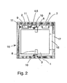
- Fig. 2 illustrates the placement of the main elevator components in the cross-section of the elevator shaft 15.
- the machinery 6 together with the traction sheave 7 is completely separated from the car 1 and counterweight.
- the machinery with the traction sheave and the counterweight are placed on the same side of the elevator car 1 between the projection of the elevator car and the shaft wall.
- the machinery is located on the opposite side of the plane of the car guide rails 10 in the shaft 15 and it is fixed to the shaft wall or floor. Mounting the machinery on a wall or on the floor provides an advantage, because if the machinery were mounted on the same guide rail as the diverting pulleys 4,5, the guide rail would have to be of a stronger design.
- Individual hoisting ropes 3 are represented by the cross-sections of the rope portions going from the diverting pulleys and traction sheave in the up and down directions.
- the car is provided with a car door 18 and the wall of the elevator shaft 15 with a landing door 17 to provide access from the landing to the elevator car 1.
- the machinery 6 Being flat in the direction of the axis of rotation of the traction sheave 7, the machinery 6 provides a space saving in the cross-sectional lay-out of the elevator shaft, because the gap between the car 1 and the wall of the shaft 15 required by such a machinery is not larger than the space needed for the counterweight.
- the diverting pulley 9 supporting the counterweight is mounted on a counterweight guide rail 11, then it is easy to place the counterweight 2 and machinery 6 on opposite sides of the elevator car 1 in the cross-sectional lay-out of the elevator shaft 15.
- a lay-out like this may be needed e.g. when several elevators are mounted in shafts placed side by side and/or back to back.
- FIG. 3 Another traction sheave elevator according to the invention is presented in the form of a diagram in Fig. 3. This is a traction sheave elevator with machinery below.
- the elevator car 101 and counterweight 102 are suspended on the hoisting ropes 103 of the elevator.
- the drive machine unit 106 of the elevator is placed in the elevator shaft, preferably in the lower part of the shaft, and the hoisting ropes 103 are passed via diverting pulleys 104,105 to the car 101 and counterweight 102.
- the diverting pulleys 104,105 are placed side, by, side and preferably separately mounted with bearings on the same axle so that they can rotate independently of each other.
- the hoisting ropes 3 consist of at least three parallel ropes.
- the elevator car 101 and the counterweight 102 travel in ⁇ the elevator shaft along car and counterweight guide rails 110,111.
- the passage of the hoisting ropes 103 is as follows: One end of the ropes is fixed to an anchorage 112 in the top part of the shaft, from where the ropes go downward to the counterweighte 102.
- the counterweight is suspended on the ropes 103 using a diverting pulley 109. From the counterweight, the ropes go up again to a first diverting pulley 105, which is mounted on an elevator guide rail 110, and from the diverting pulley 105 further to the traction sheave 107 driven by the drive machinery 106.
- the ropes From the traction sheave, the ropes go upward to a second diverting pulley 104 and round this pulley back down to the diverting pulleys 108 of the elevator car, passing below the car, and then further up to an anchorage 113 at the top part of the shaft, where the other end of the ropes is fixed.
- the elevator car 101 is suspended on the hoisting ropes 103 by means of diverting pulleys 108.
- one or more of the rope portions between the diverting pulleys or betweeen the diverting pulleys and the traction sheave 107 or between the diverting pulleys and the rope anchorages 112,113 can run in a direction differing from the exact vertical direction, making it easy to provide a sufficient distance between different rope portions or between the hoisting ropes and the other elevator components.
- the traction sheave 107 and the hoisting machinery 106 itself lie aside from the paths of both the elevator car 101 and the counterweight 102, so they can easily be placed at almost any height in the elevator shaft below the diverting pulleys 104,105. As the machinery is not placed directly above or below the counterweight or elevator car, a saving can be achieved in the height of the elevator shaft.
- a preferred embodiment is one in which that portion of the weight of the elevator car and counterweight which is supported by the diverting pulleys 4,5,104,105 is passed down via an elevator guide rail.
- the rope portions going from the traction sheave 7 to the counterweight and to the elevator car meet the diverting pulleys 4,5 from the same side (from the left in Fig. 1) of the plane between the elevator guide rails, so the weight of elevator car and counterweight is naturally applied to the diverting pulleys 8 from the opposite side of the plane between the elevator guide rails.
- the elevator in Fig. 1 the rope portions going from the traction sheave 7 to the counterweight and to the elevator car meet the diverting pulleys 4,5 from the same side (from the left in Fig. 1) of the plane between the elevator guide rails, so the weight of elevator car and counterweight is naturally applied to the diverting pulleys 8 from the opposite side of the plane between the elevator guide rails.
- the rope portions going from the traction sheave 107 to the counterweight and to the elevator car meet the diverting pulleys 104,105 from opposite sides of the plane between the elevator guide rails.
- the suspension of the elevator car and counterweight on the diverting pulleys 8 is a mirror image relative to the plane between the elevator guide rails as compared to the situation in Fig. 1. In this way, by slightly altering the rope passage, the rope suspension of the elevator car can be centered at a point where an advantageous support effect on the car is achieved.
- Fig. 4 illustrates the placement of the main components of an elevator as presented by Fig. 3 in the cross-section of the elevator shaft 15.
- the machinery 106 with the traction sheave 107 is a completely separate unit.
- Individual hoisting ropes 103 are represented by the cross-sections of the rope portions going in the up and down directions from the diverting pulleys and traction sheave.
- the car is provided with a car door 18 and the wall of the elevator shaft 15 with a landing door 17 to provide access from the landing to the elevator car 101.
- the machinery 106 Being flat in the direction of the axis of rotation of the traction sheave 107, the machinery 106 provides a space saving in the cross-sectional lay-out of the elevator shaft, because the gap between the car 101 and the wall of the shaft 15 required by such a machinery is not larger than the space needed for the counterweight.
Landscapes
- Engineering & Computer Science (AREA)
- Civil Engineering (AREA)
- Mechanical Engineering (AREA)
- Structural Engineering (AREA)
- Lift-Guide Devices, And Elevator Ropes And Cables (AREA)
- Cage And Drive Apparatuses For Elevators (AREA)
Claims (6)
- Ascenseur à poulie de traction dans lequel la machinerie d'entraínement (6, 106) avec la poulie de traction (7, 107) est placée dans la cage d'ascenseur (15) et les câbles de levage (3, 103) montent à partir de la poulie de traction (7, 107) où dans la section transversale et horizontale de la cage d'ascenseur, les projections verticales de la cabine d'ascenseur (1, 101), le contrepoids (2, 102) et la poulie de traction (7, 107) de la machinerie d'entraínement sont séparés les uns des autres et les projections verticales de la cabine d'ascenseur (1, 101), le contrepoids (2, 102) et la machinerie d'entraínement (6, 106) étant séparés les uns des autres, caractérisé en ce que la machinerie d'entraínement est d'une construction plate dans la direction de l'axe de rotation de la poulie de traction de manière à s'adapter dans l'espace situé entre la cabine (1, 101) et la paroi de la cage, caractérisé en ce que les câbles sont passés à partir de la poulie de traction (7, 107) vers le contrepoids (2, 102) et la cabine d'ascenseur (1, 101) par des poulies de déviation (4, 5, 104, 105) qui sont situées de manière parallèle l'une par rapport à l'autre et par rapport à une paroi de la cage adjacente ; les poulies de déviation étant situées l'une sur l'autre ; la poulie supérieure ayant un diamètre plus large que la poulie inférieure ou les poulies de déviation étant disposées de manière coaxiale.
- Ascenseur à poulie de traction selon la revendication 1, caractérisé en ce que la poulie de traction est une partie structurelle de la machinerie d'entraínement.
- Ascenseur à poulie de traction selon n'importe laquelle des revendications précédentes, caractérisé en ce que le contrepoids et la machinerie de levage (106) sont placés dans la cage d'ascenseur (15) sur les cotés opposés d'un plan «passant à travers les rails de guidage de l'ascenseur (110) et en ce que la cabine d'ascenseur (101) se trouve suspendue sur les câbles de levage (103) au moyen de poulies de déviation (108) du même coté de ce plan passant à travers les rails de guidage de l'ascenseur (110) ou est placée la machinerie d'entraínement.
- Ascenseur à poulie de traction selon n'importe laquelle des revendications 1-2, caractérisé en ce que le contrepoids et la machinerie de levage (6) sont placés dans la cage d'ascenseur (15) sur les cotés opposés du plan passant à travers les rails de guidage de l'ascenseur (10) et la cabine d'ascenseur (1) se trouve suspendue sur les câbles de levage (3) au moyen de poulies de traction (8) à partir du coté opposé de ce plan passant par les rails de guidage de l'ascenseur (10) par rapport à l'endroit où la machinerie d'entraínement est placée.
- Ascenseur à poulie de traction selon n'importe laquelle des revendications précédentes, caractérisé en ce que la hauteur de la cage d'ascenseur (15) est essentiellement égale à la longueur du chemin du contrepoids ensemble avec les distances de sécurité nécessaires au dessus et sous celui-ci.
- Ascenseur à poulie de traction selon n'importe laquelle des revendications 1-4, caractérisé en ce que la hauteur de la cage d'ascenseur (15) est essentiellement égale à la longueur du chemin de la cabine d'ascenseur ensemble avec les distances de sécurité nécessaires au dessus et sous celui.
Priority Applications (1)
| Application Number | Priority Date | Filing Date | Title |
|---|---|---|---|
| EP01104023A EP1112955B1 (fr) | 1995-06-22 | 1996-06-12 | Ascenseur à poulie de traction |
Applications Claiming Priority (2)
| Application Number | Priority Date | Filing Date | Title |
|---|---|---|---|
| FI953153 | 1995-06-22 | ||
| FI953153A FI100793B (fi) | 1995-06-22 | 1995-06-22 | Vetopyörähissi |
Related Child Applications (1)
| Application Number | Title | Priority Date | Filing Date |
|---|---|---|---|
| EP01104023A Division EP1112955B1 (fr) | 1995-06-22 | 1996-06-12 | Ascenseur à poulie de traction |
Publications (3)
| Publication Number | Publication Date |
|---|---|
| EP0749930A2 EP0749930A2 (fr) | 1996-12-27 |
| EP0749930A3 EP0749930A3 (fr) | 1997-02-26 |
| EP0749930B1 true EP0749930B1 (fr) | 2003-09-24 |
Family
ID=8543676
Family Applications (2)
| Application Number | Title | Priority Date | Filing Date |
|---|---|---|---|
| EP01104023A Revoked EP1112955B1 (fr) | 1995-06-22 | 1996-06-12 | Ascenseur à poulie de traction |
| EP96109415A Expired - Lifetime EP0749930B1 (fr) | 1995-06-22 | 1996-06-12 | Ascenseur à poulie de traction |
Family Applications Before (1)
| Application Number | Title | Priority Date | Filing Date |
|---|---|---|---|
| EP01104023A Revoked EP1112955B1 (fr) | 1995-06-22 | 1996-06-12 | Ascenseur à poulie de traction |
Country Status (8)
| Country | Link |
|---|---|
| US (1) | US5906251A (fr) |
| EP (2) | EP1112955B1 (fr) |
| JP (1) | JP3168161B2 (fr) |
| CN (1) | CN1099992C (fr) |
| DE (2) | DE69633347T2 (fr) |
| ES (2) | ES2225324T3 (fr) |
| FI (1) | FI100793B (fr) |
| IN (1) | IN188060B (fr) |
Cited By (1)
| Publication number | Priority date | Publication date | Assignee | Title |
|---|---|---|---|---|
| CN106053113A (zh) * | 2016-06-30 | 2016-10-26 | 天津市特种设备监督检验技术研究院 | 一种电梯曳引机可靠性试验台 |
Families Citing this family (50)
| Publication number | Priority date | Publication date | Assignee | Title |
|---|---|---|---|---|
| DE29603805U1 (de) | 1996-03-01 | 1997-07-03 | Michel Ulrich Dipl Ing | Vorrichtung zur transvenösen Kardioversion von Vorhofflimmern oder Vorhofflattern |
| DE19712646C2 (de) * | 1997-03-26 | 2000-07-13 | Heinzerling Gmbh | Seilaufzug |
| DE19752232C2 (de) * | 1997-03-26 | 2001-06-21 | Heinzerling Gmbh | Seilaufzug mit in den Aufzugschacht hineinragenden Betonsockel |
| US5931265A (en) | 1997-03-27 | 1999-08-03 | Otis Elevator Company | Rope climbing elevator |
| US6152954A (en) | 1998-07-22 | 2000-11-28 | Cardiac Pacemakers, Inc. | Single pass lead having retractable, actively attached electrode for pacing and sensing |
| US6321122B1 (en) | 1998-07-22 | 2001-11-20 | Cardiac Pacemakers, Inc. | Single pass defibrillation/pacing lead with passively attached electrode for pacing and sensing |
| US6212434B1 (en) | 1998-07-22 | 2001-04-03 | Cardiac Pacemakers, Inc. | Single pass lead system |
| US7874404B1 (en) | 1998-09-29 | 2011-01-25 | Otis Elevator Company | Elevator system having drive motor located between elevator car and hoistway sidewall |
| ES2285850T3 (es) * | 1998-02-26 | 2007-11-16 | Otis Elevator Company | Sistema de ascensor que tiene el motor de accionamiento situado en la parte inferior de la caja de ascensor. |
| US6138799A (en) * | 1998-09-30 | 2000-10-31 | Otis Elevator Company | Belt-climbing elevator having drive in counterweight |
| US7299896B1 (en) | 1998-09-29 | 2007-11-27 | Otis Elevator Company | Elevator system having drive motor located adjacent to hoistway door |
| EP1911715B1 (fr) * | 1998-02-26 | 2014-06-25 | Otis Elevator Company | Système élévateur dont le moteur d'entraînement est situé dans la partie inférieure du puits |
| US6860367B1 (en) | 1998-09-29 | 2005-03-01 | Otis Elevator Company | Elevator system having drive motor located below the elevator car |
| US6247557B1 (en) * | 1998-04-28 | 2001-06-19 | Kabushiki Kaisha Toshiba | Traction type elevator apparatus |
| CN1189379C (zh) | 1998-06-16 | 2005-02-16 | 三菱电机株式会社 | 电梯装置 |
| KR100415749B1 (ko) * | 1998-06-30 | 2004-01-24 | 미쓰비시덴키 가부시키가이샤 | 엘리베이터 장치 |
| US6501990B1 (en) | 1999-12-23 | 2002-12-31 | Cardiac Pacemakers, Inc. | Extendable and retractable lead having a snap-fit terminal connector |
| US6463334B1 (en) | 1998-11-02 | 2002-10-08 | Cardiac Pacemakers, Inc. | Extendable and retractable lead |
| US6594705B1 (en) * | 1998-09-11 | 2003-07-15 | Lv Partners, L.P. | Method and apparatus for utilizing an audibly coded signal to conduct commerce over the internet |
| US6305499B1 (en) | 1998-09-30 | 2001-10-23 | Otis Elevator Company | Drum drive elevator using flat belt |
| US6478117B2 (en) | 1998-10-30 | 2002-11-12 | Otis Elevator Company | Elevator system having governor positioned under controller in hoistway at top floor level |
| US6039152A (en) * | 1998-10-30 | 2000-03-21 | Otis Elevator Company | Elevator system with controller located under elevator landing |
| US6848543B2 (en) | 1998-10-30 | 2005-02-01 | Otis Elevator Company | Single wall interface traction elevator |
| WO2000037349A1 (fr) * | 1998-12-21 | 2000-06-29 | Mitsubishi Denki Kabushiki Kaisha | Ascenseur |
| US6085874A (en) * | 1998-12-22 | 2000-07-11 | Otis Elevator Company | Rail-climbing elevator counterweight having flat machines |
| US6202793B1 (en) | 1998-12-22 | 2001-03-20 | Richard N. Fargo | Elevator machine with counter-rotating rotors |
| US7246688B2 (en) | 1998-12-23 | 2007-07-24 | Otis Elevator Company | Elevator door system |
| FI111622B (fi) * | 1999-01-27 | 2003-08-29 | Kone Corp | Vetopyörähissi ja taittopyörän käyttö |
| JP4268275B2 (ja) * | 1999-07-09 | 2009-05-27 | 三菱電機株式会社 | エレベーター装置 |
| DE50011320D1 (de) * | 1999-08-19 | 2006-02-23 | Inventio Ag | Aufzugsanlage mit einer in einem Aufzugsschacht angeordneten Antriebseinheit |
| JP2001063935A (ja) * | 1999-08-30 | 2001-03-13 | Mitsubishi Electric Corp | エレベータ装置 |
| FI106192B (fi) * | 1999-09-16 | 2000-12-15 | Kone Corp | Hissin nostokoneisto |
| DE60043599D1 (de) * | 2000-05-22 | 2010-02-04 | Mitsubishi Electric Corp | Aufzugsvorrichtung |
| DE10034511C1 (de) * | 2000-07-15 | 2001-12-13 | Giehl Alfred | Maschinenraumloser Seilaufzug |
| JP2002167137A (ja) * | 2000-11-29 | 2002-06-11 | Toshiba Corp | エレベータ |
| FI118732B (fi) | 2000-12-08 | 2008-02-29 | Kone Corp | Hissi |
| FI4928U1 (fi) * | 2001-01-25 | 2001-05-23 | Kone Corp | Hissi |
| PL206645B1 (pl) | 2001-06-21 | 2010-09-30 | Kone Corp | Winda |
| US9573792B2 (en) | 2001-06-21 | 2017-02-21 | Kone Corporation | Elevator |
| JP3991657B2 (ja) * | 2001-11-15 | 2007-10-17 | 株式会社日立製作所 | エレベータ |
| FI119234B (fi) | 2002-01-09 | 2008-09-15 | Kone Corp | Hissi |
| JP2004075270A (ja) * | 2002-08-14 | 2004-03-11 | Toshiba Elevator Co Ltd | エレベータ装置 |
| US20060225965A1 (en) * | 2003-04-22 | 2006-10-12 | Siewert Bryan R | Elevator system without a moving counterweight |
| WO2004094289A1 (fr) * | 2003-04-22 | 2004-11-04 | Otis Elevator Company | Systeme d'ascenseur sans contrepoids de deplacement |
| ES2249198T3 (es) | 2004-02-19 | 2007-11-01 | Thyssenkrupp Aufzugswerke Gmbh | Ascensor de polea motriz sin sala de maquinas. |
| US20070131490A1 (en) * | 2004-04-22 | 2007-06-14 | Siewert Bryan R | Elevator system without a moving counterweight |
| WO2011072113A1 (fr) * | 2009-12-09 | 2011-06-16 | Thyssenkrupp Elevator Capital Corporation | Appareil ascenseur ne donnant pas de flexion inversée de câble |
| JP2013129493A (ja) * | 2011-12-21 | 2013-07-04 | Hitachi Ltd | エレベータの移動ケーブル装置 |
| DE112012006547B4 (de) | 2012-06-18 | 2019-08-14 | Mitsubishi Electric Corp. | Aufzug und Aufzugsüberholungsverfahren |
| CN106053114A (zh) * | 2016-06-30 | 2016-10-26 | 天津市特种设备监督检验技术研究院 | 一种电梯曳引机曳引力和制动力模拟试验台 |
Family Cites Families (14)
| Publication number | Priority date | Publication date | Assignee | Title |
|---|---|---|---|---|
| DE1251926B (de) * | 1965-04-28 | 1967-10-12 | Haushahn Fa C | Aufzug fuer hohe, seitlichen Ausbiegungen unterliegende Tuerme |
| FR1451792A (fr) * | 1965-10-27 | 1966-01-07 | Installation d'ascenseur avec entraînement par poulie motrice | |
| JPS5934749B2 (ja) * | 1981-08-26 | 1984-08-24 | 大日本塗料株式会社 | エポキシ樹脂塗料組成物 |
| JPS5834863U (ja) * | 1981-08-31 | 1983-03-07 | 三菱電機株式会社 | ベ−スメント式エレベ−タ |
| GB2149283B (en) * | 1983-11-08 | 1987-03-25 | Black & Decker Inc | Improvements in or relating to lawn maintenance equipment |
| AU580453B2 (en) * | 1985-11-04 | 1989-01-12 | Johns Perry Industries Pty. Ltd. | Lift sheave |
| JPH0745315B2 (ja) * | 1988-08-26 | 1995-05-17 | 三菱電機株式会社 | 巻上機 |
| FR2640949B1 (fr) * | 1988-12-22 | 1991-03-15 | Otis Elevator Co | |
| DE3922798C1 (fr) * | 1989-07-11 | 1990-09-20 | Gerhard Ing.(Grad.) 8060 Dachau De Schlosser | |
| FI894039A (fi) * | 1989-08-29 | 1991-03-02 | Kone Oy | Placering av en driftsenhet foer en his. |
| JP2666622B2 (ja) * | 1991-09-18 | 1997-10-22 | 株式会社ダイフク | 昇降設備 |
| FI94123C (fi) * | 1993-06-28 | 1995-07-25 | Kone Oy | Vetopyörähissi |
| FI98209C (fi) * | 1994-05-04 | 1997-05-12 | Kone Oy | Vetopyörähissi, nostoyksikkö ja koneistotila |
| FI93632C (fi) * | 1993-06-28 | 1995-05-10 | Kone Oy | Alakoneistoinen vetopyörähissi |
-
1995
- 1995-06-22 FI FI953153A patent/FI100793B/fi not_active IP Right Cessation
-
1996
- 1996-06-11 IN IN1084CA1996 patent/IN188060B/en unknown
- 1996-06-12 DE DE69633347T patent/DE69633347T2/de not_active Revoked
- 1996-06-12 ES ES01104023T patent/ES2225324T3/es not_active Expired - Lifetime
- 1996-06-12 EP EP01104023A patent/EP1112955B1/fr not_active Revoked
- 1996-06-12 DE DE69630081T patent/DE69630081T2/de not_active Expired - Lifetime
- 1996-06-12 ES ES96109415T patent/ES2207659T3/es not_active Expired - Lifetime
- 1996-06-12 EP EP96109415A patent/EP0749930B1/fr not_active Expired - Lifetime
- 1996-06-18 US US08/665,447 patent/US5906251A/en not_active Expired - Lifetime
- 1996-06-21 CN CN96108639A patent/CN1099992C/zh not_active Expired - Lifetime
- 1996-06-24 JP JP18169496A patent/JP3168161B2/ja not_active Expired - Fee Related
Cited By (2)
| Publication number | Priority date | Publication date | Assignee | Title |
|---|---|---|---|---|
| CN106053113A (zh) * | 2016-06-30 | 2016-10-26 | 天津市特种设备监督检验技术研究院 | 一种电梯曳引机可靠性试验台 |
| CN106053113B (zh) * | 2016-06-30 | 2018-10-02 | 天津市特种设备监督检验技术研究院 | 一种电梯曳引机可靠性试验台 |
Also Published As
| Publication number | Publication date |
|---|---|
| EP1112955B1 (fr) | 2004-09-08 |
| DE69630081T2 (de) | 2004-04-01 |
| JP3168161B2 (ja) | 2001-05-21 |
| IN188060B (fr) | 2002-08-10 |
| DE69633347D1 (de) | 2004-10-14 |
| EP1112955A1 (fr) | 2001-07-04 |
| US5906251A (en) | 1999-05-25 |
| DE69630081D1 (de) | 2003-10-30 |
| EP0749930A3 (fr) | 1997-02-26 |
| FI953153A0 (fi) | 1995-06-22 |
| CN1143044A (zh) | 1997-02-19 |
| FI100793B (fi) | 1998-02-27 |
| CN1099992C (zh) | 2003-01-29 |
| FI953153A (fi) | 1996-12-23 |
| EP0749930A2 (fr) | 1996-12-27 |
| DE69633347T2 (de) | 2005-02-10 |
| JPH09165172A (ja) | 1997-06-24 |
| ES2207659T3 (es) | 2004-06-01 |
| ES2225324T3 (es) | 2005-03-16 |
Similar Documents
| Publication | Publication Date | Title |
|---|---|---|
| EP0749930B1 (fr) | Ascenseur à poulie de traction | |
| EP0749931B1 (fr) | Ascenseur à poulie de traction | |
| FI94123B (fi) | Vetopyörähissi | |
| US5469937A (en) | Traction sheave elevator with drive machine below | |
| US6471012B2 (en) | Pulley system for a traction sheave elevator | |
| EP0710618B1 (fr) | Ascenseur à poulie de traction | |
| US5076398A (en) | Rope suspension system for an elevator | |
| JP2004520248A (ja) | エレベータ | |
| US7025177B1 (en) | Elevator system without machine | |
| JPH11246145A (ja) | エレベータのかご吊り構造 | |
| KR101014215B1 (ko) | 엘리베이터를 구성하기 위한 방법 및 엘리베이터 배송을위한 시스템 | |
| US20030188930A1 (en) | Roping configuration for traction machineroomless elevator |
Legal Events
| Date | Code | Title | Description |
|---|---|---|---|
| PUAI | Public reference made under article 153(3) epc to a published international application that has entered the european phase |
Free format text: ORIGINAL CODE: 0009012 |
|
| AK | Designated contracting states |
Kind code of ref document: A2 Designated state(s): DE ES FR IT |
|
| PUAL | Search report despatched |
Free format text: ORIGINAL CODE: 0009013 |
|
| AK | Designated contracting states |
Kind code of ref document: A3 Designated state(s): DE ES FR IT |
|
| 17P | Request for examination filed |
Effective date: 19970728 |
|
| 17Q | First examination report despatched |
Effective date: 19980127 |
|
| TPAD | Observations filed by third parties |
Free format text: ORIGINAL CODE: EPIDOS TIPA |
|
| RAP1 | Party data changed (applicant data changed or rights of an application transferred) |
Owner name: KONE CORPORATION |
|
| APAB | Appeal dossier modified |
Free format text: ORIGINAL CODE: EPIDOS NOAPE |
|
| APAB | Appeal dossier modified |
Free format text: ORIGINAL CODE: EPIDOS NOAPE |
|
| APAB | Appeal dossier modified |
Free format text: ORIGINAL CODE: EPIDOS NOAPE |
|
| APAD | Appeal reference recorded |
Free format text: ORIGINAL CODE: EPIDOS REFNE |
|
| GRAG | Despatch of communication of intention to grant |
Free format text: ORIGINAL CODE: EPIDOS AGRA |
|
| GRAG | Despatch of communication of intention to grant |
Free format text: ORIGINAL CODE: EPIDOS AGRA |
|
| GRAG | Despatch of communication of intention to grant |
Free format text: ORIGINAL CODE: EPIDOS AGRA |
|
| GRAH | Despatch of communication of intention to grant a patent |
Free format text: ORIGINAL CODE: EPIDOS IGRA |
|
| GRAH | Despatch of communication of intention to grant a patent |
Free format text: ORIGINAL CODE: EPIDOS IGRA |
|
| GRAA | (expected) grant |
Free format text: ORIGINAL CODE: 0009210 |
|
| AK | Designated contracting states |
Kind code of ref document: B1 Designated state(s): DE ES FR IT |
|
| REF | Corresponds to: |
Ref document number: 69630081 Country of ref document: DE Date of ref document: 20031030 Kind code of ref document: P |
|
| REG | Reference to a national code |
Ref country code: ES Ref legal event code: FG2A Ref document number: 2207659 Country of ref document: ES Kind code of ref document: T3 |
|
| PLBQ | Unpublished change to opponent data |
Free format text: ORIGINAL CODE: EPIDOS OPPO |
|
| ET | Fr: translation filed | ||
| PLBI | Opposition filed |
Free format text: ORIGINAL CODE: 0009260 |
|
| PLAX | Notice of opposition and request to file observation + time limit sent |
Free format text: ORIGINAL CODE: EPIDOSNOBS2 |
|
| 26 | Opposition filed |
Opponent name: SCHMITT & SOHN GMBH & CO.AUFZUGSWERKE Effective date: 20040624 |
|
| PLAX | Notice of opposition and request to file observation + time limit sent |
Free format text: ORIGINAL CODE: EPIDOSNOBS2 |
|
| PLBB | Reply of patent proprietor to notice(s) of opposition received |
Free format text: ORIGINAL CODE: EPIDOSNOBS3 |
|
| APAH | Appeal reference modified |
Free format text: ORIGINAL CODE: EPIDOSCREFNO |
|
| PLCK | Communication despatched that opposition was rejected |
Free format text: ORIGINAL CODE: EPIDOSNREJ1 |
|
| PLBN | Opposition rejected |
Free format text: ORIGINAL CODE: 0009273 |
|
| STAA | Information on the status of an ep patent application or granted ep patent |
Free format text: STATUS: OPPOSITION REJECTED |
|
| 27O | Opposition rejected |
Effective date: 20060307 |
|
| REG | Reference to a national code |
Ref country code: FR Ref legal event code: PLFP Year of fee payment: 20 |
|
| PGFP | Annual fee paid to national office [announced via postgrant information from national office to epo] |
Ref country code: DE Payment date: 20150619 Year of fee payment: 20 Ref country code: ES Payment date: 20150619 Year of fee payment: 20 |
|
| PGFP | Annual fee paid to national office [announced via postgrant information from national office to epo] |
Ref country code: IT Payment date: 20150623 Year of fee payment: 20 Ref country code: FR Payment date: 20150619 Year of fee payment: 20 |
|
| REG | Reference to a national code |
Ref country code: DE Ref legal event code: R071 Ref document number: 69630081 Country of ref document: DE |
|
| REG | Reference to a national code |
Ref country code: ES Ref legal event code: FD2A Effective date: 20160926 |
|
| PG25 | Lapsed in a contracting state [announced via postgrant information from national office to epo] |
Ref country code: ES Free format text: LAPSE BECAUSE OF EXPIRATION OF PROTECTION Effective date: 20160613 |