EP0748910B1 - Serrure multipoints - Google Patents
Serrure multipoints Download PDFInfo
- Publication number
- EP0748910B1 EP0748910B1 EP96108988A EP96108988A EP0748910B1 EP 0748910 B1 EP0748910 B1 EP 0748910B1 EP 96108988 A EP96108988 A EP 96108988A EP 96108988 A EP96108988 A EP 96108988A EP 0748910 B1 EP0748910 B1 EP 0748910B1
- Authority
- EP
- European Patent Office
- Prior art keywords
- bolt
- lock
- cam
- pivotal
- drive bar
- Prior art date
- Legal status (The legal status is an assumption and is not a legal conclusion. Google has not performed a legal analysis and makes no representation as to the accuracy of the status listed.)
- Expired - Lifetime
Links
Images


Classifications
-
- E—FIXED CONSTRUCTIONS
- E05—LOCKS; KEYS; WINDOW OR DOOR FITTINGS; SAFES
- E05C—BOLTS OR FASTENING DEVICES FOR WINGS, SPECIALLY FOR DOORS OR WINDOWS
- E05C17/00—Devices for holding wings open; Devices for limiting opening of wings or for holding wings open by a movable member extending between frame and wing; Braking devices, stops or buffers, combined therewith
- E05C17/02—Devices for holding wings open; Devices for limiting opening of wings or for holding wings open by a movable member extending between frame and wing; Braking devices, stops or buffers, combined therewith by mechanical means
- E05C17/04—Devices for holding wings open; Devices for limiting opening of wings or for holding wings open by a movable member extending between frame and wing; Braking devices, stops or buffers, combined therewith by mechanical means with a movable bar or equivalent member extending between frame and wing
- E05C17/12—Devices for holding wings open; Devices for limiting opening of wings or for holding wings open by a movable member extending between frame and wing; Braking devices, stops or buffers, combined therewith by mechanical means with a movable bar or equivalent member extending between frame and wing consisting of a single rod
- E05C17/16—Devices for holding wings open; Devices for limiting opening of wings or for holding wings open by a movable member extending between frame and wing; Braking devices, stops or buffers, combined therewith by mechanical means with a movable bar or equivalent member extending between frame and wing consisting of a single rod pivoted only at one end and having an elongated slot
- E05C17/166—Security devices
-
- E—FIXED CONSTRUCTIONS
- E05—LOCKS; KEYS; WINDOW OR DOOR FITTINGS; SAFES
- E05C—BOLTS OR FASTENING DEVICES FOR WINGS, SPECIALLY FOR DOORS OR WINDOWS
- E05C9/00—Arrangements of simultaneously actuated bolts or other securing devices at well-separated positions on the same wing
- E05C9/02—Arrangements of simultaneously actuated bolts or other securing devices at well-separated positions on the same wing with one sliding bar for fastening when moved in one direction and unfastening when moved in opposite direction; with two sliding bars moved in the same direction when fastening or unfastening
-
- E—FIXED CONSTRUCTIONS
- E05—LOCKS; KEYS; WINDOW OR DOOR FITTINGS; SAFES
- E05B—LOCKS; ACCESSORIES THEREFOR; HANDCUFFS
- E05B15/00—Other details of locks; Parts for engagement by bolts of fastening devices
- E05B15/004—Lost motion connections
Definitions
- the invention relates to a multiple locking system for a door with a pawl lock and an espagnolette lock with one over one Key operated latch, a latch and a Connecting rod with which a bolt of the Locking swivel lock can be actuated, the bolt of the locking swivel lock by means of one on the inside of the door Locking swivel lock associated side arranged Handle is lockable and by means of the drive rod is closable.
- the AT-PS 366 750 also shows a locking swivel lock, which is driven by a drive rod.
- a locking swivel lock which is driven by a drive rod.
- the bolt of the locking swivel lock both forward and backward closed via the connecting rod.
- the invention is therefore based on the object Multiple locking system training that allows that when opening the espagnolette lock, i.e. when closing the bolt, the door still goes through the bolt of the locking swivel bracket lock remains secured.
- the bolt of the espagnolette lock and the bolt of the Locking pivot lock locked which causes the door is locked, and then the bolt of the Espagnolette lock e.g. with a key closed back, then the Cam wheel of the locking swivel lock driven and that Cam wheel performs an idle stroke, so that the bolt of the Barrier lock in its pre-closed position remains and secures the door.
- the latch of the Espagnolette lock from its position releasing the door in advance, the drive rod and that are in turn Cam wheel of the locking swivel bracket lock actuated.
- the cam grips the latch on the latch Locking swivel bracket lock and closes it back.
- the door is locked by the Espagnolette lock locked. Will this closed, the door is open.
- the multiple locking system has the main advantage that when unlocking the door and locked bolt of Locking swivel lock the door a bit can be opened, but via the locking swivel bracket is held and therefore cannot be fully opened can. A complete unlocking of the door by one time The key cannot therefore be operated.
- This bracket has the main advantage that the connecting rod for coupling the locking swivel bracket lock is not interrupted or must be separated but only prepared in this way must that the bracket can be attached or hung. in the special case is the drive rod with one or more Provide recesses into which the pin provided on the bracket can intervene and the bolt of Locking swivel bracket lock past the drive rod can be anticipated. In this way, a such locking swivel lock easily retrofitted without having to replace the drive rod.
- the Recesses for coupling the bracket and for the bolt can easily be added later.
- the cam wheel preferably has two cams, the first one Cam in the working path of the drive rod or the bracket engages and the second cam with the bolt of the Locking swivel lock interacts.
- the first one Cam from a sliding body, in particular from an extension the drive rod or bracket, i.e. postponed.
- the second cam serves as a sliding body for the bolt. Becomes in this embodiment, the first cam from the drive rod driven in a first pivoting direction, then the second cam on the bolt and moves it into his closed rest position. If the first cam from the Drive rod driven into the second swivel position, then the second cam moves away from the bolt and guides you Idle stroke off.
- the cam wheel is preferred by a return spring in one Rest position kept. Will the drive rod of your one End position moved to the other end position and takes that Cam wheel over the first cam with, then come the first Cam and drive rod disengaged before the Drive rod reaches its other end position.
- the return spring then causes the cam gear to be turned back and its Takes rest position. If the drive rod is in again, this time in actuated the other direction, then the drive rod attacks the other side of the first cam and take the cam gear so far again, until just before the connecting rod yours End position takes the first cam out of engagement with the Drive rod is coming.
- the cam wheel is then in turn over the Return spring pivoted back to its rest position.
- the Return spring thus allows the cam wheel to pivot from the rest position in both swivel directions.
- a further development of the return spring provides that it a nut for the handle attacks and the nut in one or holds several defined rest positions. These rest positions correspond to the closed or closed position of the Bolt of the locking swivel bracket lock.
- the width corresponds the locking swivel lock the width of the Espagnolette lock.
- the locks can be used for milling the Ratchet swivel lock uses the same milling tool as for the milling of the espagnolette lock.
- the locking swivel bracket lock to a conventional drive rod for additional bolts can be connected, no separate one is required Cutouts in the area of the faceplate.
- the connecting rod on the back of the faceplate and / or is aligned symmetrically to this.
- the conventional milling tools can be used.
- the closing of the espagnolette lock is preferred the bolt of the locking swivel lock closed.
- the unlocking of the Locking swivel lock the door over the espagnolette lock locked and is only targeted by subsequent Unlocking of the espagnolette lock unlocked.
- the drive rod 1 is arranged symmetrically to the central plane 6 of the housing 4 and extends parallel to a faceplate 7.
- the Driving rod 1 can over the entire length of Locking swivel lock 2 formed continuously or how shown, be interrupted, the two ends of the Drive rod can be connected via a bracket 8.
- This bracket 8 is essentially C-shaped and engages its two free ends 9 and 10 in corresponding Recesses 11 and 12 of the drive rod 1. In this way can the displacement movement of a drive rod 1 over the bracket 8 are transferred to the other drive rod 1, wherein the bracket 8 is moved accordingly in the housing 4.
- This bracket 8 is plate-shaped and overlaps a bolt 13, which is closed in the drawing Location is shown.
- This bolt 13 is in the area of his free end on the top and bottom with a groove 14 and 15 provided over which he in a locked position in one Can not engage locking bracket.
- the bracket 8 is on its side facing away from the bolt 13 a wart-shaped extension 16. Will the Driving rod 1 from its one end position to its other end position moves, then the bracket 8 describes a displacement movement, in which the extension 16 of its shown in Figure 1 Layer is shifted to a position indicated by 16 ' is.
- the extension 16 In the displacement or work path of the extension 16 protrudes a first cam 17 of a cam wheel 18 which by one to Drawing plane orthogonal axis 19 is rotatable.
- the cam wheel 18 has a second cam 20 which is outside the Work path of the extension 16 is and the bolt 13th spreads.
- the bolt 13 has on its bolt extension 21 a pin 22, which is in the closed position of the bolt 13 (as shown in the drawing) outside the pivoting range of the second cam 20 is located. Is the Latch 13 pre-locked, then the pin 22 is in the position indicated at 22 '.
- bracket 5 If the bracket 5 is returned, i.e. moves up, then the Pin 16 from position 16 'in the in the drawing shown position shifted. He comes at the bottom of the first cam 17 to the system and rotates the cam wheel 18 in Clockwise direction. This will make the first leg 24 of the return spring 23 in the position indicated by 24 " deflected. As soon as the extension 16 on the first cam 17th can slide past, causes the restoring force of the Return spring 23 a return of the cam wheel 18 in the position shown in Figure 1. The swing out of the Cam wheel 18 in the clockwise direction does not effect Relocation of the bolt 13, regardless of whether this is shown in the figure 1 inferred or in the not shown pre-closed position because the second cam 20th upon rotation of the cam wheel 18 always from the pin 22 away.
- the movement of the bracket 8 corresponds upwards with the unlocking of the espagnolette lock, i.e. the Unlocking process. If latch 13 had been closed, then a door would open even if the espagnolette lock was unlocked still over the latch 13 engaging in the locking bracket be secured.
- the latch 13 is not closed by means of a illustrated twist grip, the axis of which in one Square cross section 25 of a nut 26 is mounted.
- This nut 26 is formed over part of its circumference as a pinion and engages in a section 27 of the bar extension 21, which as Rack 28 is formed.
- Lock Tooth 29 of the pinion of the nut 26 against the bolt 13 unintentional shift by hitting an edge of a Tooth 30 of the rack 28 is present.
- the nut 26 has a straight surface on its underside 31 on which the other leg 32 of the return spring 23rd is present. If the nut 26 is used to close the bolt 13 rotated counter-clockwise, then the leg 32 of the return spring 23 in a position 32 ' swung out, as with a dash-dotted line is hinted at. Since the nut 26 in the in the Figure 1 shown rest position by the leg 32 of the Return spring 23 is held defined, the Bolt 13 not automatically in a pre-closed position relocate but will be in the closed position held in which one end of an extension limiting the extension Elongated hole 33 of the bolt extension 21 on a pin 34 is present.
- FIG. 4 and 5 is a second embodiment a locking swivel lock 2 of the invention
- the cam gear 18 engages Leg 24 of a return spring 23
- the other leg 35 is supported on a stiffening rib 3 of the housing 4.
- the leg 24 is bent at its free end and engages in an elongated hole 36 of the cam wheel 18, which one in essential V-shaped recess 37 in which the Cam wheel 18 has a smaller width.
- the two Walls 38 and 39 of the V-shaped recess 37 serve as Swing limit and lie in the swung out Position of the cam wheel 18 on the leg 24 of the return spring 23 on, the leg 24 assuming the position 24 'or 24 " cranked end of the leg 24 moves in the Slot 36.
- the stable rest position of the nut 26 is determined by a spring 40 maintained, which is substantially U-shaped and has two legs 41 and 42.
- the leg 42 lies here on a stiffening rib 3 of the housing 4 and the legs 41 on the straight surface 31 of the nut 26.
- the spring 40 can as Leaf spring be formed.
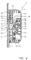
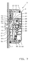
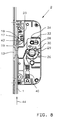
- FIGS. 6 to 8 show a third embodiment a locking swivel lock 2 of the invention
- the drive rod 1 is not running continuously, but ends at the cam gear 18. Die However, using a continuous drive rod is without further possible.
- the free end 43 of the drive rod 1 rests the cam 17 of the cam wheel 18, which around the axis 19 is rotatably mounted.
- the free end 43 of the drive rod 1 corresponds in function to the extension 16 of the bracket 8 according to the first two embodiments.
- Will the Driving rod 1 moved in the direction of arrow 44 ( Figure 8) then drives the free end 43 via the first cam 17 the cam wheel 18 and turns it clockwise the axis 19.
- a locking plate 48 is on the bolt extension 21 provided, which is also provided with an elongated hole 36, in which the pin 34 engages.
- the locking plate 48 has a second slot 49 in which one of the Bolt extension 21 engages protruding pin 50. To this The locking plate 48 is in the forward direction of the Bolt 13 with respect to the bolt extension 21 on this at least slightly displaceable, as can be seen from FIGS. 6 and 7 results.
- the bolt 13 is in its pre-closed position 7, which is done by turning the nut 26, then the tooth 29 engages not only on the rack 28 of the Bar extension 21, but also one accordingly designed edge 51 of the locking plate 48 and on the one hand shifts them together with the bar extension 21 in the closing direction of the bolt 13 and relative to Bar extension 21 or bar 13. This will allows the elongated hole 36 of the locking plate 48th is slightly longer than the slot 36 of the Bar extension 21.
- tooth 29 becomes the Nut 26 on the flank 51 of the locking plate 48 behind the Edge of the tooth of the rack 48 of the locking extension 21 so far highlighted that the lock is released.
- the second cam lies 20 additionally on the side surface 47 of the bar extension 21 and closes it back.
- the nut 26 is on the tooth 29 with respect to the axis of rotation approximately opposite side with a receiving opening into which a pin 53 of a holding arm 54 intervenes.
- This holding arm 54 is adjustable in length and with its end opposite the pin 53 pivotally mounted on a pin 55 fixed to the housing. Moreover is the holding arm 54 in the longitudinal direction of the spring 40 such biased that due to the spring force 40 of the pin 53rd is always pushed away from pin 55. That way the nut 26 in the closed position with the bolt 13 closed pushed and held there, in which the tooth 29 on one Edge of the tooth 30 of the rack 28 abuts and thereby the Rack 28 secures in the current position.
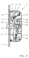
- a locking swivel lock 2 of the invention Multiple locking system is the cam wheel 18, which is also equipped with two cams 17 and 20 from Extension 16 of the drive rod 1 driven.
- the resting position of the Cam wheel 18, which is rotatable about the axis 19, is about the return spring 23 which on the pin 46 of the cam wheel 18 and is mounted on the pin 45 fixed to the housing. Furthermore this embodiment corresponds to that previously described.
Claims (13)
- Serrure multipoints pour porte avec une serrure d'entrebâilleur et une serrure à crémone avec un pêne dormant actionnable au moyen d'une clé, un pêne demi-tour et une tringle (1) permettant d'actionner un pêne dormant (13) de la serrure d'entrebâilleur (2), le pêne dormant (13) de la serrure d'entrebâilleur (2) pouvant être engagé au moyen d'une poignée agencée sur la face de la serrure d'entrebâilleur (2) qui est orientée vers l'intérieur de la porte et pouvant être dégagé au moyen de la tringle (1), caractérisée en ce qu'elle comprend une roue à cames (18) entraínée par la tringle (1) qui, dans un sens de déplacement de la tringle (1), agit sur le pêne dormant engagé (13) de la serrure d'entrebâilleur (2) en dégageant ce dernier, et qui, dans l'autre sens de déplacement de la tringle (1), effectue une course à vide par rapport au pêne dormant (13) engagé de la serrure d'entrebâilleur (2).
- Serrure multipoints selon la revendication 1, caractérisée en ce que la serrure d'entrebâilleur (2) comporte un entrebâilleur (8) s'engageant dans la tringle (1) et entraíné par cette dernière.
- Serrure multipoints selon l'une quelconque des revendications précédentes, caractérisée en ce que la roue à cames (18) comporte deux cames (17 et 20), la première came (17) s'engageant dans la course de travail de la tringle (1) ou d'un entrebâilleur (8), tandis que la seconde came (20) coopère avec le pêne dormant (13) de la serrure d'entrebâilleur (2).
- Serrure multipoints selon la revendication 3, caractérisée en ce que la première came (17) peut être déplacée par un poussoir, en particulier un prolongement (16) de la tringle (1) ou d'un entrebâilleur (8) agissant sur cette dernière.
- Serrure multipoints selon la revendication 3 ou 4, caractérisée en ce que la seconde came (20) sert de poussoir pour le pêne dormant (13) de la serrure d'entrebâilleur (2).
- Serrure multipoints selon l'une des revendications précédentes, caractérisée en ce qu'elle comporte un ressort de rappel (23) vers la position de repos de la roue à cames (18).
- Serrure multipoints selon la revendication 6, caractérisée en ce que le ressort de rappel (23) permet à la roue à cames (18) de pivoter dans les deux sens à partir de sa position de repos.
- Serrure multipoints selon la revendication 6 ou 7, caractérisée en ce que le ressort de rappel (23) sert de limiteur de pivotement.
- Serrure multipoints selon l'une des revendications 6 à 8, caractérisée en ce que le ressort de rappel (23) agit sur un fouillot pour la poignée et maintient ledit fouillot (26) en position de repos.
- Serrure multipoints selon l'une des revendications précédentes, caractérisée en ce que la largeur (b) de la serrure d'entrebâilleur (2) correspond à la largeur de la serrure à crémone.
- Serrure multipoints selon l'une des revendications précédentes, caractérisée en ce que la serrure d'entrebâilleur (2) peut être couplée à une tringle traditionnelle (1) pour pênes dormants supplémentaires.
- Serrure multipoints selon l'une des revendications précédentes, caractérisée en ce que la tringle (1) est agencée contre la face arrière d'un carénage et/ou est orientée symétriquement par rapport à ce dernier et/ou au plan médian (6) de la serrure d'entrebâilleur (2).
- Serrure multipoints selon l'une des revendications précédentes, caractérisée en ce que, lors de la fermeture de la serrure à crémone, le pêne dormant (13) de la serrure d'entrebâilleur (2) est dégagé.
Applications Claiming Priority (2)
| Application Number | Priority Date | Filing Date | Title |
|---|---|---|---|
| DE29509501U | 1995-06-14 | ||
| DE29509501U DE29509501U1 (de) | 1995-06-14 | 1995-06-14 | Mehrfachverriegelungsanlage |
Publications (3)
| Publication Number | Publication Date |
|---|---|
| EP0748910A2 EP0748910A2 (fr) | 1996-12-18 |
| EP0748910A3 EP0748910A3 (fr) | 1997-06-18 |
| EP0748910B1 true EP0748910B1 (fr) | 2001-09-12 |
Family
ID=8009155
Family Applications (1)
| Application Number | Title | Priority Date | Filing Date |
|---|---|---|---|
| EP96108988A Expired - Lifetime EP0748910B1 (fr) | 1995-06-14 | 1996-06-05 | Serrure multipoints |
Country Status (3)
| Country | Link |
|---|---|
| EP (1) | EP0748910B1 (fr) |
| AT (1) | ATE205572T1 (fr) |
| DE (2) | DE29509501U1 (fr) |
Families Citing this family (3)
| Publication number | Priority date | Publication date | Assignee | Title |
|---|---|---|---|---|
| DE19841544C2 (de) * | 1998-09-11 | 2000-11-16 | Fuhr Carl Gmbh & Co | Zusatzschloß an einem Treibstangenverschluß |
| AT407066B (de) * | 1999-02-17 | 2000-12-27 | Roto Frank Eisenwaren | Türfängerverschluss |
| CN103321481B (zh) * | 2013-07-16 | 2016-01-06 | 陈俊 | 一种门锁转体组件 |
Family Cites Families (5)
| Publication number | Priority date | Publication date | Assignee | Title |
|---|---|---|---|---|
| FR95567E (fr) * | 1968-02-12 | 1971-03-26 | Ferco | Crémones pour portes. |
| AT366750B (de) * | 1980-11-13 | 1982-05-10 | Grundmann Rohrbacher Schlosser | Tuerverschluss |
| FR2576628B1 (fr) * | 1985-01-30 | 1989-06-30 | Grundmann Rohrbacher Schlosser | Fermeture de porte comprenant une serrure avec verrou et cremaillere et un element de verrouillage de securite relie a la serrure. |
| AT393710B (de) * | 1990-06-27 | 1991-12-10 | Roto Frank Eisenwaren | Mehrriegelverschluss |
| DE29509503U1 (de) * | 1995-06-14 | 1995-09-14 | Gretsch Unitas Gmbh | Mehrfachverriegelungsanlage |
-
1995
- 1995-06-14 DE DE29509501U patent/DE29509501U1/de not_active Expired - Lifetime
-
1996
- 1996-06-05 EP EP96108988A patent/EP0748910B1/fr not_active Expired - Lifetime
- 1996-06-05 DE DE59607657T patent/DE59607657D1/de not_active Expired - Lifetime
- 1996-06-05 AT AT96108988T patent/ATE205572T1/de not_active IP Right Cessation
Also Published As
| Publication number | Publication date |
|---|---|
| DE29509501U1 (de) | 1996-10-17 |
| EP0748910A3 (fr) | 1997-06-18 |
| ATE205572T1 (de) | 2001-09-15 |
| EP0748910A2 (fr) | 1996-12-18 |
| DE59607657D1 (de) | 2001-10-18 |
Similar Documents
| Publication | Publication Date | Title |
|---|---|---|
| DE102006059568B4 (de) | Schließanlage für Türen, Fenster oder dergleichen, insbesondere Treibstangenschloss mit Panikfunktion und Mehrpunktverriegelung | |
| EP0526522B1 (fr) | Fermeture a levier pivotant verrouillee par une serrure a pompe | |
| DE3505379C1 (de) | Treibstangenschloß | |
| DE3503466C2 (fr) | ||
| EP0634552B1 (fr) | Clef avec pêne rotatif, spécialement comme serrure supplémentaire à barres coulissantes | |
| DE4114007C2 (de) | Treibstangenverschluß | |
| EP0748910B1 (fr) | Serrure multipoints | |
| DE3034764C2 (de) | Betätigungsvorrichtung für Treibstangenbeschläge | |
| DE60008223T2 (de) | Türbefestigungsvorrichtung | |
| EP0454959A2 (fr) | Serrure de barre coulissante manoeuvrable d'un barillet | |
| DE19815671B4 (de) | Treibstangenverschluß | |
| EP0298292B1 (fr) | Serrure de porte à pêne et demi-tour coulissants | |
| AT386038B (de) | Tuerverschluss | |
| DE3427713A1 (de) | Mehrtourig schliessendes treibstangenschloss | |
| EP0592012A1 (fr) | Crémone | |
| DE3408917C2 (fr) | ||
| EP0454958A1 (fr) | Serrure, notamment serrure avec bielle motrice | |
| EP0940535B1 (fr) | Serrure, notamment serrure à mortaise | |
| AT394607B (de) | Mehrfachverriegelung | |
| EP0990758A2 (fr) | Serrure additionelle pour crémone | |
| EP1024240B1 (fr) | Dispositif de verrouillage | |
| DE4302920C2 (de) | Schloß, insbesondere Einsteckschloß | |
| DE19828365C1 (de) | Schloß für schall- und/oder wärmedämmende Türen | |
| DE102007035123B4 (de) | Kippsicherung | |
| DE60209682T2 (de) | Verbindungsvorrichtung für Verlängerung der Treibstange und der Stulpschiene eines Treibstangenschlosses odgl |
Legal Events
| Date | Code | Title | Description |
|---|---|---|---|
| PUAI | Public reference made under article 153(3) epc to a published international application that has entered the european phase |
Free format text: ORIGINAL CODE: 0009012 |
|
| AK | Designated contracting states |
Kind code of ref document: A2 Designated state(s): AT BE CH DE FR GB IT LI NL |
|
| PUAL | Search report despatched |
Free format text: ORIGINAL CODE: 0009013 |
|
| AK | Designated contracting states |
Kind code of ref document: A3 Designated state(s): AT BE CH DE FR GB IT LI NL |
|
| 17P | Request for examination filed |
Effective date: 19970716 |
|
| 17Q | First examination report despatched |
Effective date: 19990316 |
|
| GRAG | Despatch of communication of intention to grant |
Free format text: ORIGINAL CODE: EPIDOS AGRA |
|
| GRAG | Despatch of communication of intention to grant |
Free format text: ORIGINAL CODE: EPIDOS AGRA |
|
| GRAG | Despatch of communication of intention to grant |
Free format text: ORIGINAL CODE: EPIDOS AGRA |
|
| GRAH | Despatch of communication of intention to grant a patent |
Free format text: ORIGINAL CODE: EPIDOS IGRA |
|
| GRAH | Despatch of communication of intention to grant a patent |
Free format text: ORIGINAL CODE: EPIDOS IGRA |
|
| GRAA | (expected) grant |
Free format text: ORIGINAL CODE: 0009210 |
|
| AK | Designated contracting states |
Kind code of ref document: B1 Designated state(s): AT BE CH DE FR GB IT LI NL |
|
| REF | Corresponds to: |
Ref document number: 205572 Country of ref document: AT Date of ref document: 20010915 Kind code of ref document: T |
|
| REG | Reference to a national code |
Ref country code: CH Ref legal event code: NV Representative=s name: TROESCH SCHEIDEGGER WERNER AG Ref country code: CH Ref legal event code: EP |
|
| REF | Corresponds to: |
Ref document number: 59607657 Country of ref document: DE Date of ref document: 20011018 |
|
| GBT | Gb: translation of ep patent filed (gb section 77(6)(a)/1977) |
Effective date: 20011117 |
|
| REG | Reference to a national code |
Ref country code: GB Ref legal event code: IF02 |
|
| ET | Fr: translation filed | ||
| PLBE | No opposition filed within time limit |
Free format text: ORIGINAL CODE: 0009261 |
|
| STAA | Information on the status of an ep patent application or granted ep patent |
Free format text: STATUS: NO OPPOSITION FILED WITHIN TIME LIMIT |
|
| 26N | No opposition filed | ||
| PGFP | Annual fee paid to national office [announced via postgrant information from national office to epo] |
Ref country code: NL Payment date: 20070615 Year of fee payment: 12 Ref country code: CH Payment date: 20070615 Year of fee payment: 12 |
|
| PGFP | Annual fee paid to national office [announced via postgrant information from national office to epo] |
Ref country code: GB Payment date: 20070621 Year of fee payment: 12 |
|
| PGFP | Annual fee paid to national office [announced via postgrant information from national office to epo] |
Ref country code: IT Payment date: 20070627 Year of fee payment: 12 |
|
| PGFP | Annual fee paid to national office [announced via postgrant information from national office to epo] |
Ref country code: BE Payment date: 20070711 Year of fee payment: 12 |
|
| PGFP | Annual fee paid to national office [announced via postgrant information from national office to epo] |
Ref country code: AT Payment date: 20080616 Year of fee payment: 13 |
|
| PGFP | Annual fee paid to national office [announced via postgrant information from national office to epo] |
Ref country code: FR Payment date: 20080613 Year of fee payment: 13 |
|
| BERE | Be: lapsed |
Owner name: *GRETSCH-UNITAS G.M.B.H. BAUBESCHLAGE Effective date: 20080630 |
|
| REG | Reference to a national code |
Ref country code: CH Ref legal event code: PL |
|
| GBPC | Gb: european patent ceased through non-payment of renewal fee |
Effective date: 20080605 |
|
| NLV4 | Nl: lapsed or anulled due to non-payment of the annual fee |
Effective date: 20090101 |
|
| PG25 | Lapsed in a contracting state [announced via postgrant information from national office to epo] |
Ref country code: BE Free format text: LAPSE BECAUSE OF NON-PAYMENT OF DUE FEES Effective date: 20080630 |
|
| PG25 | Lapsed in a contracting state [announced via postgrant information from national office to epo] |
Ref country code: NL Free format text: LAPSE BECAUSE OF NON-PAYMENT OF DUE FEES Effective date: 20090101 |
|
| PG25 | Lapsed in a contracting state [announced via postgrant information from national office to epo] |
Ref country code: LI Free format text: LAPSE BECAUSE OF NON-PAYMENT OF DUE FEES Effective date: 20080630 Ref country code: GB Free format text: LAPSE BECAUSE OF NON-PAYMENT OF DUE FEES Effective date: 20080605 Ref country code: CH Free format text: LAPSE BECAUSE OF NON-PAYMENT OF DUE FEES Effective date: 20080630 |
|
| PG25 | Lapsed in a contracting state [announced via postgrant information from national office to epo] |
Ref country code: IT Free format text: LAPSE BECAUSE OF NON-PAYMENT OF DUE FEES Effective date: 20080605 |
|
| REG | Reference to a national code |
Ref country code: FR Ref legal event code: ST Effective date: 20100226 |
|
| PG25 | Lapsed in a contracting state [announced via postgrant information from national office to epo] |
Ref country code: FR Free format text: LAPSE BECAUSE OF NON-PAYMENT OF DUE FEES Effective date: 20090630 |
|
| PG25 | Lapsed in a contracting state [announced via postgrant information from national office to epo] |
Ref country code: AT Free format text: LAPSE BECAUSE OF NON-PAYMENT OF DUE FEES Effective date: 20090605 |
|
| PGFP | Annual fee paid to national office [announced via postgrant information from national office to epo] |
Ref country code: DE Payment date: 20100625 Year of fee payment: 15 |
|
| REG | Reference to a national code |
Ref country code: DE Ref legal event code: R119 Ref document number: 59607657 Country of ref document: DE Effective date: 20120103 |
|
| PG25 | Lapsed in a contracting state [announced via postgrant information from national office to epo] |
Ref country code: DE Free format text: LAPSE BECAUSE OF NON-PAYMENT OF DUE FEES Effective date: 20120103 |