EP0746080A1 - Machine tournante comprenant une structure résistante à l'eau - Google Patents
Machine tournante comprenant une structure résistante à l'eau Download PDFInfo
- Publication number
- EP0746080A1 EP0746080A1 EP96108462A EP96108462A EP0746080A1 EP 0746080 A1 EP0746080 A1 EP 0746080A1 EP 96108462 A EP96108462 A EP 96108462A EP 96108462 A EP96108462 A EP 96108462A EP 0746080 A1 EP0746080 A1 EP 0746080A1
- Authority
- EP
- European Patent Office
- Prior art keywords
- air gap
- bearing
- bearing box
- base portion
- cylindrical base
- Prior art date
- Legal status (The legal status is an assumption and is not a legal conclusion. Google has not performed a legal analysis and makes no representation as to the accuracy of the status listed.)
- Granted
Links
- XLYOFNOQVPJJNP-UHFFFAOYSA-N water Substances O XLYOFNOQVPJJNP-UHFFFAOYSA-N 0.000 title description 54
- 229910052751 metal Inorganic materials 0.000 claims description 6
- 239000002184 metal Substances 0.000 claims description 6
- 230000002093 peripheral effect Effects 0.000 claims description 2
- 238000005452 bending Methods 0.000 claims 1
- XEEYBQQBJWHFJM-UHFFFAOYSA-N Iron Chemical compound [Fe] XEEYBQQBJWHFJM-UHFFFAOYSA-N 0.000 description 16
- 239000000463 material Substances 0.000 description 10
- 150000003839 salts Chemical class 0.000 description 9
- 229910052742 iron Inorganic materials 0.000 description 8
- 238000007789 sealing Methods 0.000 description 8
- 238000001816 cooling Methods 0.000 description 5
- 230000001965 increasing effect Effects 0.000 description 4
- 238000004804 winding Methods 0.000 description 4
- 210000000078 claw Anatomy 0.000 description 3
- 229910001209 Low-carbon steel Inorganic materials 0.000 description 2
- 239000003792 electrolyte Substances 0.000 description 2
- 230000004907 flux Effects 0.000 description 2
- 239000007921 spray Substances 0.000 description 2
- 238000003466 welding Methods 0.000 description 2
- QTBSBXVTEAMEQO-UHFFFAOYSA-M Acetate Chemical compound CC([O-])=O QTBSBXVTEAMEQO-UHFFFAOYSA-M 0.000 description 1
- 241000743339 Agrostis Species 0.000 description 1
- 229910052782 aluminium Inorganic materials 0.000 description 1
- XAGFODPZIPBFFR-UHFFFAOYSA-N aluminium Chemical compound [Al] XAGFODPZIPBFFR-UHFFFAOYSA-N 0.000 description 1
- 230000002528 anti-freeze Effects 0.000 description 1
- 230000004323 axial length Effects 0.000 description 1
- 238000005259 measurement Methods 0.000 description 1
- 238000012986 modification Methods 0.000 description 1
- 230000004048 modification Effects 0.000 description 1
- 230000001105 regulatory effect Effects 0.000 description 1
- 238000009877 rendering Methods 0.000 description 1
- 230000000717 retained effect Effects 0.000 description 1
- 238000004904 shortening Methods 0.000 description 1
Images


Classifications
-
- H—ELECTRICITY
- H02—GENERATION; CONVERSION OR DISTRIBUTION OF ELECTRIC POWER
- H02K—DYNAMO-ELECTRIC MACHINES
- H02K5/00—Casings; Enclosures; Supports
- H02K5/04—Casings or enclosures characterised by the shape, form or construction thereof
- H02K5/10—Casings or enclosures characterised by the shape, form or construction thereof with arrangements for protection from ingress, e.g. water or fingers
-
- H—ELECTRICITY
- H02—GENERATION; CONVERSION OR DISTRIBUTION OF ELECTRIC POWER
- H02K—DYNAMO-ELECTRIC MACHINES
- H02K5/00—Casings; Enclosures; Supports
- H02K5/04—Casings or enclosures characterised by the shape, form or construction thereof
- H02K5/12—Casings or enclosures characterised by the shape, form or construction thereof specially adapted for operating in liquid or gas
- H02K5/124—Sealing of shafts
-
- H—ELECTRICITY
- H02—GENERATION; CONVERSION OR DISTRIBUTION OF ELECTRIC POWER
- H02K—DYNAMO-ELECTRIC MACHINES
- H02K7/00—Arrangements for handling mechanical energy structurally associated with dynamo-electric machines, e.g. structural association with mechanical driving motors or auxiliary dynamo-electric machines
- H02K7/10—Structural association with clutches, brakes, gears, pulleys or mechanical starters
- H02K7/1004—Structural association with clutches, brakes, gears, pulleys or mechanical starters with pulleys
-
- H—ELECTRICITY
- H02—GENERATION; CONVERSION OR DISTRIBUTION OF ELECTRIC POWER
- H02K—DYNAMO-ELECTRIC MACHINES
- H02K5/00—Casings; Enclosures; Supports
- H02K5/04—Casings or enclosures characterised by the shape, form or construction thereof
- H02K5/16—Means for supporting bearings, e.g. insulating supports or means for fitting bearings in the bearing-shields
- H02K5/173—Means for supporting bearings, e.g. insulating supports or means for fitting bearings in the bearing-shields using bearings with rolling contact, e.g. ball bearings
Definitions
- the present invention relates to a rotary machine which is driven by a driving power source such as an engine through a belt and, more particularly, relates to a water-resistant structure of an alternator for a vehicle.
- USP 5,194,770 (which corresponds to JA-A-4-140042) discloses an alternator for a vehicle which is equipped with a labyrinth between the V-pulley and the housing to prevent water coming into the housing through the shaft.
- the labyrinth of the alternator disclosed in the above publication is too simple to prevent water from entering the housing if the alternator is mounted under the engine of a vehicle which has no under-cover, where the alternator is subject to splashing of water or mud, resulting in decrease of the bearing life. Even if a sealed bearing, which has sealing members on opposite sides of the bearing between the outer race fixed to the housing and the inner race fixed to the rotating shaft, is adopted, water may enter the inside through gaps between the sealing member which is fixed to the outer race and the inner race (the gap for allowing rotation of the inner race), resulting in shortening the ball-bearing life.
- the present invention has an object of providing an improved rotary machine which can prevent water from entering the inside of a bearing through a sealing member, thereby increasing life time of the bearing.
- a further object of the present invention is to provide a rotary machine in which drainage of water from a labyrinth or an air gap formed between the pulley and the housing prevents water from entering the inside of the bearing through the seal member.
- Another object of the present invention is to provide a rotary machine in which corrosive materials is not produced even if water enters the inside of the bearing.
- Further object of the present invention is to provide a rotary machine in which gaps may not form between the bearing box and the outer periphery of the bearing.
- the rotary machine comprises a housing having a front wall and a bearing box for supporting an outer race of a bearing having a sealing member, and a bowl-shaped rotating member, such as a pulley, having a cylindrical base portion disposed around the bearing box, a boss portion fixed to a rotary shaft and an annular portion connecting the cylindrical base portion and the boss portions, thereby forming an air gap between the rotating member and the housing extending from an opening portion to the bearing.
- a bowl-shaped rotating member such as a pulley
- the air gap has four different air gaps: a first air gap formed between the rear end of the cylindrical base portion and the front wall, a second air gap formed between an inner periphery of the cylindrical base portion and the bearing box, a third air gap formed between the rear surface of the annular portion and the front surface of the bearing box and a fourth air gap formed between the rear surface of the boss portion and the front surface of the sealing member.
- They are formed to satisfy the following inequality: ⁇ 1 ⁇ ⁇ 2, ⁇ 2 > ⁇ 3, ⁇ 3 > ⁇ 4 when the first air gap is ⁇ 1, the second air gap is ⁇ 2, the third air gap is ⁇ 3 and the fourth air gap is ⁇ 4.
- the first air gap near the opening is formed as a narrow space
- the second air gap adjacent to the first air gap is formed wider than the first air gap
- the third air gap adjacent to the second air gap is formed as a narrow space
- the fourth air gap adjacent to the third air gap is formed narrower than the third air gap.
- water entering the fourth air gap is easier to move to the third air gap, which is wider than the fourth air gap, than to move to the bearing through the sealing member.
- the water in the third air gap is also easier to move to the second air gap, which is wider than the third air gap, than to move to the fourth air gap.
- the water in the second air gap is easier to move to the first air gap than to move to the third air gap. Even if water enters the air gap between the pulley and the housing, the water is more apt to flow to the first air gap near the opening than to flow to the fourth or third air gap near the bearing, thus the water is prevented from entering the bearing to keep the normal life time of the bearing.
- the air gap may comprise a first air gap formed between the rear end of the cylindrical base portion and the front wall, a second air gap formed approximately perpendicular to the first air gap between the inner periphery of the cylindrical base portion and the bearing box, a third air gap formed approximately perpendicular to the second air gap between the rear surface of the annular portion and the front surface of the bearing box and a fourth air gap disposed spaced apart from and in parallel with the third air gap between the rear end of the boss portion and the front surface of said sealing member.
- the air gap from the first air gap near the opening of the air gap through the second and third air gaps which are located at middle portions to the fourth air gap near the bearing is bent so that the water is prevented from rushing to the fourth air gap near the bearing from the first air gap near the opening straightly.
- the water since the water may not get in the bearing through the seal member, decrease in the life time of the bearing can be prevented.
- the outer race of the bearing is preferably press-fitted into the bearing box. That is, the outer periphery of the bearing support is formed smooth so that the second air gap formed between the inner periphery of the outer cylindrical portion of the pulley and the front surface of the bearing support of the housing can be formed into a cylindrical shape having a uniform axial length. Accordingly, the water can flow from the second air gap to the first air gap near the opening straightly.
- the bearing box preferably has a retaining portion for retaining the outer race of the bearing from the front end and radial size of the fourth air gap is preferably larger than that of a fifth air gap formed between the rear surface of the inner peripheral portion of the retaining portion and the front surface of the sealing member. Since the fourth air gap is formed wider than the fifth air gap thereby to hold the water getting into the fourth air gap rather by the inner cylindrical portion than by the retaining portion, the water held by the inner cylindrical portion is thrown out by centrifugal force during rotation of the pulley.
- the inner periphery of the cylindrical base portion has preferably an inclination so that an opening-side diameter of the second air gap becomes larger than a bottom-side diameter. Therefore, the centrifugal force causes the water in the second air gap to flow to the first air gap near the opening straightly.
- the bearing box and the rotating member are preferably made of the same kind of metal. Accordingly, such corrosive material may not be produced even if salt water gets into the second or third air gap.
- the outer race of the bearing and the bearing box are also preferably made of the same kind of metal. Therefore, gaps otherwise generated by difference in the thermal expansion are prevented from forming between the outer periphery of the bearing and the bearing support portion.
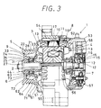
- FIG. 1 and FIG. 2 illustrate a main structure of a vehicle alternator and FIG. 3 illustrates an overall structure of the vehicle alternator.
- the vehicle alternator 1 is a rotary machine according to the present invention.
- the vehicle alternator 1 is composed of a shaft 2, a rotor 3 rotatable with the shaft 2, a stator 4 disposed around the rotor 3, a V-ribbed pulley 5, two ball bearings 6 and 7, a housing 8 rotatably supporting the shaft 2 through the ball bearings 6 and 7.
- An air gap (labyrinth or water passage) 9 is formed between the V-ribbed pulley 5 and the housing 8.
- the rotor 3 is composed of a Lundel-type pole core 10, a field coil 11 and two slip rings 12.
- the pole core 10 has a plurality of claw portions each of which extends alternately from opposite sides of the pole core in parallel with each other. Cooling fans 13 are fixed to the opposite ends of the pole core 10 respectively to draw cooling air into the housing 8.
- the field coil 11 is wound in a bobbin 14 which is disposed in the middle of the pole core 10.
- Each one of the slip rings 12 is secured to an end of the shaft 2 and disposed to be in contact with one of two brushes 15 at the peripheries thereof respectively.
- the brushes 15 are held in a brush holder 16 secured inside the housing 8.
- the stator 4 is composed of a stator core 17 disposed around the pole core 10 and three-phase armature windings (or stator coils) 18.
- the armature core 17 is a laminated core of thin magnetic plates and press-fitted into the housing 8.
- the armature core 17 is provided with magnetic flux passages so that the magnetic flux flowing from the claw portions of the pole core 10 can effectively interlink the three-phase armature windings 18.
- a plurality of slots (not shown) are formed at an equal interval in the inner periphery of the armature core 17.
- the three-phase armature windings 18 are connected in the Y or ⁇ -connection mode to generate three-phase AC output power when the rotor 3 rotates.
- the V-ribbed pulley 5 is a pulley for a poly-V belt, that is, a member of a transmitting unit for transmitting the engine driving force to the rotor 3 through the poly-V belt (not shown).
- the V-ribbed pulley 5 is made of flat metal plate of iron material (such as low-carbon steel), which is press-formed into a bowl unit.
- the V-ribbed pulley 5 is composed of an outer cylindrical base portion 21, two belt guides 22 and 23 disposed opposite ends of the base portion 21, an annular portion 24 extending inwardly from an edge of the base portion 21 and a boss portion 25 disposed at the center thereof.
- the base portion 21 is an approximately cylindrical member having a plurality of V-shaped groove 26 for receiving a poly-V belt on the outer periphery thereof.
- the base portion 21 has an inner surface inclined at an angle ⁇ (1 ° , for example) with the diameter of the opening portion of the air gap being larger than the diameter of the bottom as shown in FIG. 2.
- the base portion 21 of the V-ribbed pulley 5 according to this embodiment has the inner diameter of about 50 mm.
- the V-shaped grooves 26 are formed by a forming roller.
- the belt guides 22 and 23 prevent the poly-V belt from running off the V-ribbed pulley 5 and also the water shelter (water-resistant member) which prevents water from entering the ball bearing 6 as described later.
- the annular portion 24 is an annular plate for connecting the edge of the base portion 21 and an end of the boss portion 25.
- the boss portion 25 is approximately cylindrical member extending longitudinally from the inner periphery of the annular portion 24 and is connected to an end of the shaft 2 by a nut-and-washer 27.
- the boss portion 25 is disposed in contact with the ball bearing 6 to restrict the axial movement of the ball bearing 6a and prevents water from entering the bearing 6.
- the ball bearing 6 is a two-side sealed ball bearing which is composed of an inner race 31, an outer race 32, a plurality of balls 33 and two bearing seal members 34 and 35.
- the inner race 31 is fixed to the outer periphery of a portion of the shaft 2 between the boss portion 25 of the V-ribbed pulley 5 and the pole core 10 of the rotor 3 and is rotated together with the shaft 2.
- One end of the inner race 31 is disposed in contact or engagement with the rear end of the boss portion 25 so that the axial movement of the shaft 2 can be retained.
- the inner race 31 engages an end of the pole core at the rear end thereof through a space collar 36 to restrain the axial movement of the shaft 2.
- the inner race 31 has a plurality of hemispherical hollows 37 on the outer periphery thereof to accommodate the balls 33 rotatably and grooves 38 and 39 on the opposite sides of the hollows 37 to retain slidably the bearing seal members 34 and 35.
- the outer race 32 is disposed around the inner race 31 which is press-fitted into an inner periphery of a bearing box 62 of the housing 8 without specific fastening member.
- the front end of the outer race 32 engages a rear end of a flange portion 63 of the bearing box 62 to restrain the axial movement of the shaft 2.
- the rear end of the outer race 32 engages the front end of a retainer plate 64 to restrain the axial movement of the shaft 2.
- the outer race 32 has a plurality of hemispherical hollows 41 on the inner periphery thereof to accommodate the balls 33 rotatably with the hollows 37 of the inner race 31 and grooves 42 and 43 on the opposite sides of the hollows 41 to retain slidably the bearing seal members 34 and 35 with the grooves 38 and 39 of the inner race 31.
- the retainer plate 64 is fixed to an inner portion of the housing 8 by welding or another fixing member.
- the balls 33 can be replaced with rollers or the like members.
- the bearing seal members 34 and 35 are annular iron plates molded with resinous rubber for preventing water from entering the inside 44 of the bearing 6.
- the housing 8 is composed of a drive-side frame 51, a rear frame 52 and a rear cover 53.
- the drive-side frame 51 and the rear frame 52 hold the rotor 3 and the stator 4 and are mounted in an engine.
- the drive-side frame 51 and the rear frame 52 are directly coupled together by a plurality of stud bolts 54.
- a plurality of cooling air window are opened in the drive-side frame 51 and the rear frame 52 respectively to introduce cooling air drawn by both cooling fans 13.
- the brushes 15, a rectifying unit 57 and output terminals (not shown) are fixed between the rear frame 52 and a rear cover 53.
- the brush holder 16, the rectifying 57 and an IC regulator 58 are secured by fastening members such as screws.
- the rectifying unit 57 is composed of a plurality of diodes (not shown) for converting AC current into DC current.
- the rectifying unit 57 is connected to electric loads and a battery (not shown) mounted on a vehicle.
- the IC regulator 58 turns on or off a switching element such as a transistor connected between the field coil 11 and an earth (not shown) to control the field current supplied to the field coil, thereby regulating the output voltage of the vehicle alternator 1.
- a switching element such as a transistor connected between the field coil 11 and an earth (not shown) to control the field current supplied to the field coil, thereby regulating the output voltage of the vehicle alternator 1.
- the drive-side frame 51 is press-formed from a plate of iron material (such as low-carbon steel) to have an annular front wall 61 disposed to face the rear belt guide 23 of the base portion 21 of the V-ribbed pulley 5 and the bearing box 62 which extends axially forward from an inner end of the end wall 61.
- a plate of iron material such as low-carbon steel
- the bearing box 62 has a cylindrical portion disposed longitudinally between the base portion 21 of the V-ribbed pulley 5 and the outer race 32 of the ball bearing 6.
- the bearing box 62 has an inner periphery to which the outer race 32 of the ball bearing 6 is press-fitted.
- the approximately annular flange portion 63 is formed at the forward end of the bearing box 62 to support the outer race 32 of the ball bearing 6.
- the flange portion 63 is disposed to face the bearing seal member 34 to restrain the axial movement of the outer race 32 of the ball bearing 6 with the retainer plate 64 which is fixed by spot welding or the like to an inner surface of the drive frame 51.
- the air gap 9 is a space extending from an opening 70 and the bearing seal member 34 and is formed of a first to fifth air gaps 71 - 75.
- the first air gap 71 is located near the opening 70 between the rear surface of the belt guide 23 of the V-ribbed pulley 5 and a front surface of the front wall 61 of the drive-side frame 51 and is an annular flat space which inclines backward at a certain angle.
- the second air gap 72 is a middle space adjacent to the first air gap 71 which bents in a direction approximately perpendicular to the first air gap 71.
- the second air gap 72 is formed between the inner periphery of the base portion 21 of the V-ribbed pulley 5 and the outer periphery of the bearing box 62 and is an approximately cylindrical space extending in parallel with the shaft 2.
- the second air gap 72 has longer axial extension than the first and third to fifth air gaps 73 - 75 have.
- the third air gap 73 is a middle space adjacent to the second air gap 72, as shown in FIG. 1 and FIG. 2, and bends in a direction perpendicular to the second air gap 72.
- the third air gap 73 is located between the rear end surface of the annular portion 24 of the V-ribbed pulley 5 and the front surface of the flange portion 63 of the bearing box 62 and is an annular flat space extending in the radial direction of the shaft 2.
- the fourth air gap 74 is, as shown in FIG. 2, a space adjacent to the third space 73 near the bearing seal member 34 (inmost side) and is located spaced apart from and in parallel with the third air gap 73.
- the fourth air gap 74 is located between the rear end surface of the boss portion 25 of the V ribbed pulley 5 and a radially inner front surface of the bearing seal member 34 and is an annular flat space extending in the radial direction of the shaft.
- the fifth air gap 75 is a space adjacent to the third air gap 73 located near the bearing seal member 34 (inmost side) in parallel with the third air gap 73 at a certain distance and coaxially around the fourth air gap 74.
- the fifth air gap 75 is located between the rear surface of the flange portion 63 of the bearing box 62 and a radially outer front surface of the bearing seal member 34 and is an annular flat space extending in the radial direction of the shaft 2.
- the distances are decided to satisfy the following inequalities E1 through E3.
- ⁇ 1 is about 1.2 mm
- ⁇ 2 is about 3.0 mm
- ⁇ 3 is about 0.2 mm
- ⁇ 5 is about 0.2 mm.
- the radial size of the fourth air gap 74 is (d2 - d1) and the radial size of the fifth air gap 75 is (d4 - d3), the radial size is decided to satisfy the following inequality E4.
- the vehicle alternator 1 is mounted at a place under the engine in general. If the vehicle has no under cover, the alternator is subject to splash of muddy water, which may enter the ball bearing 6 behind the bearing seal member 34 through the air gap 9 formed between the V-ribbed pulley 5 and the drive-side frame 51.
- the vehicle alternator according to this embodiment has an air gap 9 which is composed of the narrow first air gap near the opening 70, the widest second air gap 72 adjacent to the first air gap 71, and the third air gap 73 which is adjacent to the second air gap 72 and is narrower than the second air gap.
- the fourth air gap 74 adjacent to the third air gap 73 and the fifth air gap 75 adjacent to the third air gap 73 are narrower than the third air gap 73.
- the bearing box 62 used to have outer thick portions (four portions, for example) for providing screw holes to retain the outer race 32 of the ball bearing 6 by screws, rendering the second air gap 72 narrower.
- outer thick portions four portions, for example
- the outer race 32 of the ball bearing 6 is press-fitted to the inside of the bearing box 62, the outer race 32 can be fixed without a fastening member, so that the outer portion of the bearing box 62 becomes straight without undulations.
- the outer portion of the bearing box 62 can be made approximately cylindrical shape having a smooth surface so that the second air gap formed between the inner surface of base portion 21 of the V-ribbed pulley 5 and the front surface of the bearing box 62 of the drive-side frame 51 can be formed into a longitudinally straight cylindrical space. Accordingly, water getting into the second air gap 72 drains off easily to the opening 70.
- the inner periphery of the base portion 21 of the V-ribbed pulley 5 forming the outer periphery of the second air gap 72 inclines at a certain angle ⁇ (1° ) so that the inside diameter of the opening 70 becomes larger than the inside diameter of the bottom portion of the second air gap 72, water getting into the second air gap 72 is drained by the centrifugal force out of the opening 70.
- the boss portion 25 of the V-ribbed pulley which is a rotating wall forming the fourth air gap 74 with the bearing seal member 34 is radially wider than the wall of the flange portion 63 which is a stationary wall forming the fifth air gap 75 with the bearing seal member 34. Accordingly, water getting into the fourth air gap 74 is apt to adhere more to the boss portion 25 than to the flange portion 63 so that the water adhering to the boss portion 25 is rotated and thrown out by the centrifugal force from the fourth air gap 74 to the opening 70.
- the drainage of the water in the air gap 9 between the V-ribbed pulley 5 and the drive frame 51 can be carried out through the opening 70 by increasing or reducing the spaces of the air gap 9 (especially increase of the second air gap 72).
- water is prevented from entering the ball bearing 6 through the bearing seal member 34 so that life time of the ball bearing 6 can be increased.
- the bearing box 62 and the V-ribbed pulley 5 are made of the same kind of iron material, even if a small quantity of water including some electrolyte enters the second or the third air gap, the electrolyte-including water may not form a bridge between the bearing box 62 and the V-ribbed pulley 5 and, consequently, the local cell may not be formed thereby preventing corrosive materials from forming inside the bearing seal member 34 of the ball bearing 6. Thus, water is kept from entering the inside the bearing seal member 34 of the bearing 6.
- the outer race 32 of the ball bearing 6 and the bearing box 62 are heated by the alternator 1 and expand. Since the outer race 32 of the ball bearing 6 and the bearing box 62 are made of the same kind of iron material, gaps due to difference in the thermal expansion does not form between the outer race 32 of the bearing 6 and the bearing box 62. Since the drive-side frame 51 is press-formed from iron material, burrs are scarcely formed as compared with what is casted.
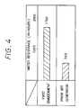
- salt spray test in which salt water (electrolyte-including water) is sprayed on all sides of the alternator, is applied.
- FIG. 4 shows a test result when the salt water of 350 cc is sprayed on the respective alternators (the first embodiment and the conventional alternator) running at 4,000 rpm for 15 seconds every one minute through sixty nozzles of 1.2 mm in diameter.
- the vehicle alternator 1 according to the first embodiment has the salt resistance of 1700 hours, which is three times as long as the salt resistance of 560 hours which the conventional alternator has.
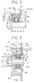
- FIG. 5 shows a main portion of a vehicle alternator according to a second embodiment.
- the V-ribbed pulley 5 is press-formed or roller-formed from a plate made of an iron material.
- the ball bearing 6 is inserted into the bearing box 62 of the drive-side frame 51 until it abuts a front surface of a folded portion 65 of the bearing box 62 and is fixed by a retaining portion 66 at the front surface of the outer race 32.
- the outer periphery of the ball bearing 6 becomes round and the cross-section thereof becomes cylindrical also in this case. Since the outer race 32 is held between the folded portion 65 and the retaining portion 66, no retainer plate 64 of the first embodiment is necessary.
- the third air gap 73 can be formed accurately. Accordingly, the axial distance ⁇ 3 of the third air gap 73, or the axial distance between the rear surface of the annular portion 24 of the V-ribbed pulley 5 and the front surface of the retaining portion 66 of the bearing box 62 can be reduced, thereby, to shelter the ball bearing 6 from water effectively.
- FIG. 6 shows a main part of an vehicle alternator according to a third embodiment of the present invention.
- the belt guide 23 of the V-ribbed pulley 5 and the front wall 61 of the drive-side frame 51 are disposed axially in parallel with each other to be perpendicular to the shaft 2. Accordingly, the first air gap 71 becomes an annular flat space which is disposed on the same axis as the opening 70.
- the first air gap 71 is formed into an annular flat space, the rear surface of the belt guide 23 of the V-ribbed pulley 5 and the front wall 61 of the drive-side frame 51 are located in an approximately flat space which is disposed radially outside the shaft 2. As a result, water entering the first air gap 71 drops straight away without entering the ball bearing 6, increasing effect of sheltering water from the bearing.
- the present invention can be applied to an AC or a DC generator driven by a motor, a water wheel of a wind wheel.
- the present invention can be also applied to a rotary machine such as a motor, a compressor or a rotary pump.
- V-ribbed pulley 5 with the poly-V-belt is used, V-pulley with a single V-groove can be used also.
- the V-ribbed pulley can be also replaced with a rotating member such as a gear or the like.
- the shaft 2 and the V-ribbed pulley 5 are separately formed. However, they can be formed in a unit.
- the inner race 31 of the ball bearing 6 can be formed integral with the shaft 2.
- the outer race 32 of the ball bearing 6 can be formed integral with the bearing box 62 also.
- the front wall 61 can be separated from the bearing box also.
- the flange portion 63 can be separated from the bearing box too.
- a labyrinth or air gap (9) formed between a pulley (5) and a housing (8) of a rotary machine such as an alternator (1) is arranged to have a plurality of differently-shaped air gaps.
- the size of a first air gap between a belt guide of the pulley is ⁇ 1
- the size of a second air gap formed between a cylindrical base portion (21) of the pulley (5) and a bearing box (62)of the housing (8) is ⁇ 2
- a third air gap formed between a front wall (61) and a flange portion (63) of the bearing box (62) is ⁇ 3
- a fourth air gap formed between a boss portion (25) and a bearing seal member ( 34) is ⁇ 4
- the air gap is arranged to satisfy the following inequality: ⁇ 1 ⁇ ⁇ 2, ⁇ 2 > ⁇ 3, ⁇ 3 > ⁇ 4.
Landscapes
- Engineering & Computer Science (AREA)
- Power Engineering (AREA)
- Motor Or Generator Frames (AREA)
- Rolling Contact Bearings (AREA)
Applications Claiming Priority (2)
| Application Number | Priority Date | Filing Date | Title |
|---|---|---|---|
| JP130201/95 | 1995-05-29 | ||
| JP13020195A JP3480122B2 (ja) | 1995-05-29 | 1995-05-29 | 発電機 |
Publications (2)
| Publication Number | Publication Date |
|---|---|
| EP0746080A1 true EP0746080A1 (fr) | 1996-12-04 |
| EP0746080B1 EP0746080B1 (fr) | 1999-01-13 |
Family
ID=15028517
Family Applications (1)
| Application Number | Title | Priority Date | Filing Date |
|---|---|---|---|
| EP96108462A Expired - Lifetime EP0746080B1 (fr) | 1995-05-29 | 1996-05-28 | Machine tournante comprenant une structure résistante à l'eau |
Country Status (6)
| Country | Link |
|---|---|
| US (1) | US5726511A (fr) |
| EP (1) | EP0746080B1 (fr) |
| JP (1) | JP3480122B2 (fr) |
| KR (1) | KR100295177B1 (fr) |
| CN (1) | CN1044181C (fr) |
| DE (1) | DE69601326T2 (fr) |
Cited By (5)
| Publication number | Priority date | Publication date | Assignee | Title |
|---|---|---|---|---|
| WO2001022559A1 (fr) * | 1999-09-17 | 2001-03-29 | Robert Bosch Gmbh | Machine electrique avec joint de fente annulaire |
| EP1452776A2 (fr) * | 2000-10-26 | 2004-09-01 | Koyo Seiko Co., Ltd. | Poulie |
| EP1471270A1 (fr) * | 2002-01-31 | 2004-10-27 | Nsk Ltd., | Palier de poulie pour accessoire de moteur d'automobile |
| EP1649579B1 (fr) * | 2003-07-31 | 2007-02-14 | Valeo Equipements Electriques Moteur | Alternateur comportant des moyens perfectionnes pour eliminer les charges electrostatiques |
| FR3073340A1 (fr) * | 2017-11-08 | 2019-05-10 | Valeo Equipements Electriques Moteur | Plaquette de roulement pour machine electrique tournante |
Families Citing this family (17)
| Publication number | Priority date | Publication date | Assignee | Title |
|---|---|---|---|---|
| US6137201A (en) | 1997-05-26 | 2000-10-24 | Denso Corporation | AC generator for vehicles |
| KR20030072661A (ko) * | 2002-03-06 | 2003-09-19 | 한국델파이주식회사 | 자동차용 교류발전기용 드라이버 엔드 프레임 |
| JP2003269329A (ja) * | 2002-03-15 | 2003-09-25 | Sanden Corp | 自動車用コンプレッサ |
| JP4540974B2 (ja) * | 2003-12-16 | 2010-09-08 | Ntn株式会社 | 補機駆動用ベルトの張力調整装置 |
| US6952062B1 (en) * | 2004-07-02 | 2005-10-04 | Mancl Dennis J | Seal and bearing assembly for a motor |
| GB2435912B (en) * | 2006-03-06 | 2008-05-14 | Honda Motor Co Ltd | Electric motor and electric power steering apparatus |
| JP4800111B2 (ja) * | 2006-05-23 | 2011-10-26 | 三菱電機株式会社 | 電動機 |
| US8387898B1 (en) | 2009-02-17 | 2013-03-05 | Scott C. Mancl | Paint sprayer with bearing protection |
| US9509191B2 (en) * | 2011-09-29 | 2016-11-29 | Panasonic Intellectual Property Management Co., Ltd. | Electric motor with ball bearing assembly for rotary shaft |
| JP6002474B2 (ja) * | 2012-06-29 | 2016-10-05 | 古野電気株式会社 | レーダアンテナ装置 |
| KR101470171B1 (ko) * | 2013-06-20 | 2014-12-09 | 현대자동차주식회사 | 차량의 모터제너레이터 |
| DE102016102911B4 (de) * | 2016-02-19 | 2021-11-25 | Hanon Systems | Kältemittelkompressor |
| US10156240B2 (en) | 2016-06-16 | 2018-12-18 | Scott C. Mancl | Motor-driven fan with trapped adhesive for minimizing vibration |
| JP6428737B2 (ja) * | 2016-09-29 | 2018-11-28 | トヨタ自動車株式会社 | 回転電機システム |
| JP7283102B2 (ja) * | 2019-02-12 | 2023-05-30 | 株式会社デンソー | 回転電機 |
| US11336148B2 (en) * | 2019-04-02 | 2022-05-17 | Hanon Systems EFP Canada Ltd. | Pulley assisted electromagnetic fluid pump |
| EP3767800A1 (fr) * | 2019-07-19 | 2021-01-20 | Mahle International GmbH | Machine électrique |
Citations (7)
| Publication number | Priority date | Publication date | Assignee | Title |
|---|---|---|---|---|
| DE3025735A1 (de) * | 1980-07-08 | 1982-02-04 | Robert Bosch Gmbh, 7000 Stuttgart | Elektrische maschine |
| EP0231785A2 (fr) * | 1986-01-30 | 1987-08-12 | Mitsubishi Denki Kabushiki Kaisha | Générateur à courant alternatif pour véhicules |
| GB2205693A (en) * | 1987-06-08 | 1988-12-14 | Mitsuba Electric Mfg Co | Alternating current generator for automotive vehicles |
| FR2667460A1 (fr) * | 1990-09-28 | 1992-04-03 | Mitsubishi Electric Corp | Alternateur de vehicule. |
| EP0503503A1 (fr) * | 1991-03-08 | 1992-09-16 | Mitsubishi Denki Kabushiki Kaisha | Carter de palier pour machine électrique tournante |
| GB2268546A (en) * | 1992-07-03 | 1994-01-12 | Bosch Gmbh Robert | Sealing electric machines |
| FR2693514A1 (fr) * | 1992-07-10 | 1994-01-14 | Baglin Richard | Perfectionnement aux pompes centrifuges. |
Family Cites Families (3)
| Publication number | Priority date | Publication date | Assignee | Title |
|---|---|---|---|---|
| JPH0522897A (ja) * | 1991-07-12 | 1993-01-29 | Hitachi Ltd | 車両用交流発電機 |
| US5334097A (en) * | 1992-01-07 | 1994-08-02 | Toyota Jidosha Kabushiki Kaisha | Toroidal type continuously variable transmission supported by a common bearing and reaction stationary shaft |
| US5423304A (en) * | 1994-10-31 | 1995-06-13 | Chrysler Corporation | Mechanically driven centrifugal air compressor with integral plastic pulley and internal helical ring gear |
-
1995
- 1995-05-29 JP JP13020195A patent/JP3480122B2/ja not_active Expired - Fee Related
-
1996
- 1996-05-21 US US08/651,930 patent/US5726511A/en not_active Expired - Fee Related
- 1996-05-28 EP EP96108462A patent/EP0746080B1/fr not_active Expired - Lifetime
- 1996-05-28 DE DE69601326T patent/DE69601326T2/de not_active Expired - Fee Related
- 1996-05-29 KR KR1019960018475A patent/KR100295177B1/ko not_active IP Right Cessation
- 1996-05-29 CN CN96105318A patent/CN1044181C/zh not_active Expired - Fee Related
Patent Citations (8)
| Publication number | Priority date | Publication date | Assignee | Title |
|---|---|---|---|---|
| DE3025735A1 (de) * | 1980-07-08 | 1982-02-04 | Robert Bosch Gmbh, 7000 Stuttgart | Elektrische maschine |
| EP0231785A2 (fr) * | 1986-01-30 | 1987-08-12 | Mitsubishi Denki Kabushiki Kaisha | Générateur à courant alternatif pour véhicules |
| GB2205693A (en) * | 1987-06-08 | 1988-12-14 | Mitsuba Electric Mfg Co | Alternating current generator for automotive vehicles |
| FR2667460A1 (fr) * | 1990-09-28 | 1992-04-03 | Mitsubishi Electric Corp | Alternateur de vehicule. |
| US5194770A (en) * | 1990-09-28 | 1993-03-16 | Mitsubishi Denki K.K. | Vehicular a.c. generator |
| EP0503503A1 (fr) * | 1991-03-08 | 1992-09-16 | Mitsubishi Denki Kabushiki Kaisha | Carter de palier pour machine électrique tournante |
| GB2268546A (en) * | 1992-07-03 | 1994-01-12 | Bosch Gmbh Robert | Sealing electric machines |
| FR2693514A1 (fr) * | 1992-07-10 | 1994-01-14 | Baglin Richard | Perfectionnement aux pompes centrifuges. |
Cited By (9)
| Publication number | Priority date | Publication date | Assignee | Title |
|---|---|---|---|---|
| WO2001022559A1 (fr) * | 1999-09-17 | 2001-03-29 | Robert Bosch Gmbh | Machine electrique avec joint de fente annulaire |
| EP1452776A2 (fr) * | 2000-10-26 | 2004-09-01 | Koyo Seiko Co., Ltd. | Poulie |
| EP1452776A3 (fr) * | 2000-10-26 | 2006-03-15 | Koyo Seiko Co., Ltd. | Poulie |
| EP1471270A1 (fr) * | 2002-01-31 | 2004-10-27 | Nsk Ltd., | Palier de poulie pour accessoire de moteur d'automobile |
| EP1471270A4 (fr) * | 2002-01-31 | 2005-08-10 | Nsk Ltd | Palier de poulie pour accessoire de moteur d'automobile |
| US7163341B2 (en) | 2002-01-31 | 2007-01-16 | Nsk Ltd. | Bearing to be used for pulley in auxiliary device for engine |
| EP1649579B1 (fr) * | 2003-07-31 | 2007-02-14 | Valeo Equipements Electriques Moteur | Alternateur comportant des moyens perfectionnes pour eliminer les charges electrostatiques |
| FR3073340A1 (fr) * | 2017-11-08 | 2019-05-10 | Valeo Equipements Electriques Moteur | Plaquette de roulement pour machine electrique tournante |
| WO2019092034A1 (fr) * | 2017-11-08 | 2019-05-16 | Valeo Equipements Electriques Moteur | Plaquette de roulement pour machine electrique tournante |
Also Published As
| Publication number | Publication date |
|---|---|
| EP0746080B1 (fr) | 1999-01-13 |
| KR960043438A (ko) | 1996-12-23 |
| US5726511A (en) | 1998-03-10 |
| JPH08322185A (ja) | 1996-12-03 |
| DE69601326D1 (de) | 1999-02-25 |
| JP3480122B2 (ja) | 2003-12-15 |
| DE69601326T2 (de) | 1999-07-01 |
| CN1140353A (zh) | 1997-01-15 |
| KR100295177B1 (ko) | 2001-09-17 |
| CN1044181C (zh) | 1999-07-14 |
Similar Documents
| Publication | Publication Date | Title |
|---|---|---|
| US5726511A (en) | Rotary machine having water-resistant structure | |
| US5696415A (en) | Electric rotary machine | |
| EP0762617B1 (fr) | Alternateur pour véhicule | |
| EP0772279B1 (fr) | Générateur de courant alternatif pour véhicule | |
| US8810101B2 (en) | Electric rotary machine having claw magnetic poles with flanges having centrifugal force resistance | |
| US5751088A (en) | Alternator for vehicle | |
| EP1089417A2 (fr) | Alternateur de véhicule automobile | |
| US20060279161A1 (en) | Rotary electric machine equipped with stator core designed to ensure machine performance | |
| US7168923B2 (en) | Alternator fan | |
| US20060170298A1 (en) | Liquid spray shield for liquid-cooled alternators | |
| JPH0870554A (ja) | 発電機 | |
| JP3055451B2 (ja) | 車両用交流発電機 | |
| US20080012448A1 (en) | Brushless alternator for vehicles | |
| US20040160138A1 (en) | Dynamoelectric machine | |
| US7687952B2 (en) | Brushless alternator with stationary shaft | |
| JP3294497B2 (ja) | 交流発電機 | |
| US6259182B1 (en) | Car AC generator with a slip ring support and a slinger unit that cooperate to form a labyrinth that prevents fluid entry into an interior chamber | |
| JP3382825B2 (ja) | 車両用交流発電機の回転子 | |
| JPH01318532A (ja) | ブラシレス交流発電機の回転子 | |
| US7078837B1 (en) | Method and apparatus for contamination protection for bearing assembly | |
| JPH0937519A (ja) | 車両用交流発電機 | |
| JP2003018793A (ja) | 車両用交流発電システム及びそれに用いられる車両用交流発電機 | |
| JP3644126B2 (ja) | 交流発電機 | |
| JPH11332178A (ja) | 車両用交流発電機 | |
| RU2194350C1 (ru) | Бесконтактный когтеобразный генератор |
Legal Events
| Date | Code | Title | Description |
|---|---|---|---|
| PUAI | Public reference made under article 153(3) epc to a published international application that has entered the european phase |
Free format text: ORIGINAL CODE: 0009012 |
|
| AK | Designated contracting states |
Kind code of ref document: A1 Designated state(s): DE FR GB IT |
|
| 17P | Request for examination filed |
Effective date: 19961122 |
|
| 17Q | First examination report despatched |
Effective date: 19970422 |
|
| RAP1 | Party data changed (applicant data changed or rights of an application transferred) |
Owner name: DENSO CORPORATION |
|
| GRAG | Despatch of communication of intention to grant |
Free format text: ORIGINAL CODE: EPIDOS AGRA |
|
| GRAG | Despatch of communication of intention to grant |
Free format text: ORIGINAL CODE: EPIDOS AGRA |
|
| GRAH | Despatch of communication of intention to grant a patent |
Free format text: ORIGINAL CODE: EPIDOS IGRA |
|
| GRAH | Despatch of communication of intention to grant a patent |
Free format text: ORIGINAL CODE: EPIDOS IGRA |
|
| GRAA | (expected) grant |
Free format text: ORIGINAL CODE: 0009210 |
|
| AK | Designated contracting states |
Kind code of ref document: B1 Designated state(s): DE FR GB IT |
|
| ITF | It: translation for a ep patent filed | ||
| ET | Fr: translation filed | ||
| REF | Corresponds to: |
Ref document number: 69601326 Country of ref document: DE Date of ref document: 19990225 |
|
| REG | Reference to a national code |
Ref country code: GB Ref legal event code: 746 Effective date: 19990625 |
|
| PLBE | No opposition filed within time limit |
Free format text: ORIGINAL CODE: 0009261 |
|
| STAA | Information on the status of an ep patent application or granted ep patent |
Free format text: STATUS: NO OPPOSITION FILED WITHIN TIME LIMIT |
|
| 26N | No opposition filed | ||
| REG | Reference to a national code |
Ref country code: GB Ref legal event code: IF02 |
|
| PGFP | Annual fee paid to national office [announced via postgrant information from national office to epo] |
Ref country code: DE Payment date: 20080605 Year of fee payment: 13 |
|
| PGFP | Annual fee paid to national office [announced via postgrant information from national office to epo] |
Ref country code: IT Payment date: 20080526 Year of fee payment: 13 |
|
| PGFP | Annual fee paid to national office [announced via postgrant information from national office to epo] |
Ref country code: GB Payment date: 20080528 Year of fee payment: 13 |
|
| GBPC | Gb: european patent ceased through non-payment of renewal fee |
Effective date: 20090528 |
|
| REG | Reference to a national code |
Ref country code: FR Ref legal event code: ST Effective date: 20100129 |
|
| PG25 | Lapsed in a contracting state [announced via postgrant information from national office to epo] |
Ref country code: FR Free format text: LAPSE BECAUSE OF NON-PAYMENT OF DUE FEES Effective date: 20090602 |
|
| PGFP | Annual fee paid to national office [announced via postgrant information from national office to epo] |
Ref country code: FR Payment date: 20080514 Year of fee payment: 13 |
|
| PG25 | Lapsed in a contracting state [announced via postgrant information from national office to epo] |
Ref country code: GB Free format text: LAPSE BECAUSE OF NON-PAYMENT OF DUE FEES Effective date: 20090528 |
|
| PG25 | Lapsed in a contracting state [announced via postgrant information from national office to epo] |
Ref country code: DE Free format text: LAPSE BECAUSE OF NON-PAYMENT OF DUE FEES Effective date: 20091201 |
|
| PG25 | Lapsed in a contracting state [announced via postgrant information from national office to epo] |
Ref country code: IT Free format text: LAPSE BECAUSE OF NON-PAYMENT OF DUE FEES Effective date: 20090528 |