EP0744739B1 - Verfahren zur Herstellung einer optischen Platte und dazu verwendete Plattform - Google Patents
Verfahren zur Herstellung einer optischen Platte und dazu verwendete Plattform Download PDFInfo
- Publication number
- EP0744739B1 EP0744739B1 EP96107914A EP96107914A EP0744739B1 EP 0744739 B1 EP0744739 B1 EP 0744739B1 EP 96107914 A EP96107914 A EP 96107914A EP 96107914 A EP96107914 A EP 96107914A EP 0744739 B1 EP0744739 B1 EP 0744739B1
- Authority
- EP
- European Patent Office
- Prior art keywords
- resin
- adhesive
- placing platform
- suction
- boss
- Prior art date
- Legal status (The legal status is an assumption and is not a legal conclusion. Google has not performed a legal analysis and makes no representation as to the accuracy of the status listed.)
- Expired - Lifetime
Links
- 230000003287 optical effect Effects 0.000 title claims description 34
- 238000004519 manufacturing process Methods 0.000 title claims description 12
- 229920005989 resin Polymers 0.000 claims description 184
- 239000011347 resin Substances 0.000 claims description 184
- 239000000758 substrate Substances 0.000 claims description 138
- 239000000853 adhesive Substances 0.000 claims description 64
- 230000001070 adhesive effect Effects 0.000 claims description 64
- 238000003892 spreading Methods 0.000 claims description 23
- 239000007788 liquid Substances 0.000 claims description 7
- 239000011248 coating agent Substances 0.000 claims description 4
- 238000000576 coating method Methods 0.000 claims description 4
- 238000000034 method Methods 0.000 claims description 4
- 238000003848 UV Light-Curing Methods 0.000 description 46
- 239000003570 air Substances 0.000 description 13
- 238000012986 modification Methods 0.000 description 9
- 230000004048 modification Effects 0.000 description 9
- 238000003860 storage Methods 0.000 description 4
- 238000004891 communication Methods 0.000 description 3
- 238000001723 curing Methods 0.000 description 3
- 230000003796 beauty Effects 0.000 description 2
- 239000004840 adhesive resin Substances 0.000 description 1
- 229920006223 adhesive resin Polymers 0.000 description 1
- XAGFODPZIPBFFR-UHFFFAOYSA-N aluminium Chemical compound [Al] XAGFODPZIPBFFR-UHFFFAOYSA-N 0.000 description 1
- 229910052782 aluminium Inorganic materials 0.000 description 1
- 239000012080 ambient air Substances 0.000 description 1
- 230000006866 deterioration Effects 0.000 description 1
- ZZUFCTLCJUWOSV-UHFFFAOYSA-N furosemide Chemical compound C1=C(Cl)C(S(=O)(=O)N)=CC(C(O)=O)=C1NCC1=CC=CO1 ZZUFCTLCJUWOSV-UHFFFAOYSA-N 0.000 description 1
- 239000012943 hotmelt Substances 0.000 description 1
- 208000015181 infectious disease Diseases 0.000 description 1
- 238000001746 injection moulding Methods 0.000 description 1
- 230000001788 irregular Effects 0.000 description 1
- 238000000465 moulding Methods 0.000 description 1
- 230000035515 penetration Effects 0.000 description 1
- 229920000515 polycarbonate Polymers 0.000 description 1
- 239000004417 polycarbonate Substances 0.000 description 1
- 229920005668 polycarbonate resin Polymers 0.000 description 1
- 239000004431 polycarbonate resin Substances 0.000 description 1
- 238000011160 research Methods 0.000 description 1
Images





Classifications
-
- B—PERFORMING OPERATIONS; TRANSPORTING
- B29—WORKING OF PLASTICS; WORKING OF SUBSTANCES IN A PLASTIC STATE IN GENERAL
- B29C—SHAPING OR JOINING OF PLASTICS; SHAPING OF MATERIAL IN A PLASTIC STATE, NOT OTHERWISE PROVIDED FOR; AFTER-TREATMENT OF THE SHAPED PRODUCTS, e.g. REPAIRING
- B29C65/00—Joining or sealing of preformed parts, e.g. welding of plastics materials; Apparatus therefor
- B29C65/48—Joining or sealing of preformed parts, e.g. welding of plastics materials; Apparatus therefor using adhesives, i.e. using supplementary joining material; solvent bonding
- B29C65/52—Joining or sealing of preformed parts, e.g. welding of plastics materials; Apparatus therefor using adhesives, i.e. using supplementary joining material; solvent bonding characterised by the way of applying the adhesive
- B29C65/521—Joining or sealing of preformed parts, e.g. welding of plastics materials; Apparatus therefor using adhesives, i.e. using supplementary joining material; solvent bonding characterised by the way of applying the adhesive by spin coating
-
- B—PERFORMING OPERATIONS; TRANSPORTING
- B29—WORKING OF PLASTICS; WORKING OF SUBSTANCES IN A PLASTIC STATE IN GENERAL
- B29C—SHAPING OR JOINING OF PLASTICS; SHAPING OF MATERIAL IN A PLASTIC STATE, NOT OTHERWISE PROVIDED FOR; AFTER-TREATMENT OF THE SHAPED PRODUCTS, e.g. REPAIRING
- B29C65/00—Joining or sealing of preformed parts, e.g. welding of plastics materials; Apparatus therefor
- B29C65/02—Joining or sealing of preformed parts, e.g. welding of plastics materials; Apparatus therefor by heating, with or without pressure
- B29C65/14—Joining or sealing of preformed parts, e.g. welding of plastics materials; Apparatus therefor by heating, with or without pressure using wave energy, i.e. electromagnetic radiation, or particle radiation
- B29C65/1403—Joining or sealing of preformed parts, e.g. welding of plastics materials; Apparatus therefor by heating, with or without pressure using wave energy, i.e. electromagnetic radiation, or particle radiation characterised by the type of electromagnetic or particle radiation
- B29C65/1406—Ultraviolet [UV] radiation
-
- B—PERFORMING OPERATIONS; TRANSPORTING
- B29—WORKING OF PLASTICS; WORKING OF SUBSTANCES IN A PLASTIC STATE IN GENERAL
- B29C—SHAPING OR JOINING OF PLASTICS; SHAPING OF MATERIAL IN A PLASTIC STATE, NOT OTHERWISE PROVIDED FOR; AFTER-TREATMENT OF THE SHAPED PRODUCTS, e.g. REPAIRING
- B29C65/00—Joining or sealing of preformed parts, e.g. welding of plastics materials; Apparatus therefor
- B29C65/02—Joining or sealing of preformed parts, e.g. welding of plastics materials; Apparatus therefor by heating, with or without pressure
- B29C65/14—Joining or sealing of preformed parts, e.g. welding of plastics materials; Apparatus therefor by heating, with or without pressure using wave energy, i.e. electromagnetic radiation, or particle radiation
- B29C65/1429—Joining or sealing of preformed parts, e.g. welding of plastics materials; Apparatus therefor by heating, with or without pressure using wave energy, i.e. electromagnetic radiation, or particle radiation characterised by the way of heating the interface
- B29C65/1435—Joining or sealing of preformed parts, e.g. welding of plastics materials; Apparatus therefor by heating, with or without pressure using wave energy, i.e. electromagnetic radiation, or particle radiation characterised by the way of heating the interface at least passing through one of the parts to be joined, i.e. transmission welding
-
- B—PERFORMING OPERATIONS; TRANSPORTING
- B29—WORKING OF PLASTICS; WORKING OF SUBSTANCES IN A PLASTIC STATE IN GENERAL
- B29C—SHAPING OR JOINING OF PLASTICS; SHAPING OF MATERIAL IN A PLASTIC STATE, NOT OTHERWISE PROVIDED FOR; AFTER-TREATMENT OF THE SHAPED PRODUCTS, e.g. REPAIRING
- B29C65/00—Joining or sealing of preformed parts, e.g. welding of plastics materials; Apparatus therefor
- B29C65/02—Joining or sealing of preformed parts, e.g. welding of plastics materials; Apparatus therefor by heating, with or without pressure
- B29C65/14—Joining or sealing of preformed parts, e.g. welding of plastics materials; Apparatus therefor by heating, with or without pressure using wave energy, i.e. electromagnetic radiation, or particle radiation
- B29C65/1477—Joining or sealing of preformed parts, e.g. welding of plastics materials; Apparatus therefor by heating, with or without pressure using wave energy, i.e. electromagnetic radiation, or particle radiation making use of an absorber or impact modifier
- B29C65/1483—Joining or sealing of preformed parts, e.g. welding of plastics materials; Apparatus therefor by heating, with or without pressure using wave energy, i.e. electromagnetic radiation, or particle radiation making use of an absorber or impact modifier coated on the article
-
- B—PERFORMING OPERATIONS; TRANSPORTING
- B29—WORKING OF PLASTICS; WORKING OF SUBSTANCES IN A PLASTIC STATE IN GENERAL
- B29C—SHAPING OR JOINING OF PLASTICS; SHAPING OF MATERIAL IN A PLASTIC STATE, NOT OTHERWISE PROVIDED FOR; AFTER-TREATMENT OF THE SHAPED PRODUCTS, e.g. REPAIRING
- B29C65/00—Joining or sealing of preformed parts, e.g. welding of plastics materials; Apparatus therefor
- B29C65/48—Joining or sealing of preformed parts, e.g. welding of plastics materials; Apparatus therefor using adhesives, i.e. using supplementary joining material; solvent bonding
- B29C65/4805—Joining or sealing of preformed parts, e.g. welding of plastics materials; Apparatus therefor using adhesives, i.e. using supplementary joining material; solvent bonding characterised by the type of adhesives
- B29C65/483—Reactive adhesives, e.g. chemically curing adhesives
- B29C65/4845—Radiation curing adhesives, e.g. UV light curing adhesives
-
- B—PERFORMING OPERATIONS; TRANSPORTING
- B29—WORKING OF PLASTICS; WORKING OF SUBSTANCES IN A PLASTIC STATE IN GENERAL
- B29C—SHAPING OR JOINING OF PLASTICS; SHAPING OF MATERIAL IN A PLASTIC STATE, NOT OTHERWISE PROVIDED FOR; AFTER-TREATMENT OF THE SHAPED PRODUCTS, e.g. REPAIRING
- B29C65/00—Joining or sealing of preformed parts, e.g. welding of plastics materials; Apparatus therefor
- B29C65/48—Joining or sealing of preformed parts, e.g. welding of plastics materials; Apparatus therefor using adhesives, i.e. using supplementary joining material; solvent bonding
- B29C65/52—Joining or sealing of preformed parts, e.g. welding of plastics materials; Apparatus therefor using adhesives, i.e. using supplementary joining material; solvent bonding characterised by the way of applying the adhesive
- B29C65/54—Joining or sealing of preformed parts, e.g. welding of plastics materials; Apparatus therefor using adhesives, i.e. using supplementary joining material; solvent bonding characterised by the way of applying the adhesive between pre-assembled parts
- B29C65/544—Joining or sealing of preformed parts, e.g. welding of plastics materials; Apparatus therefor using adhesives, i.e. using supplementary joining material; solvent bonding characterised by the way of applying the adhesive between pre-assembled parts by suction
-
- B—PERFORMING OPERATIONS; TRANSPORTING
- B29—WORKING OF PLASTICS; WORKING OF SUBSTANCES IN A PLASTIC STATE IN GENERAL
- B29C—SHAPING OR JOINING OF PLASTICS; SHAPING OF MATERIAL IN A PLASTIC STATE, NOT OTHERWISE PROVIDED FOR; AFTER-TREATMENT OF THE SHAPED PRODUCTS, e.g. REPAIRING
- B29C66/00—General aspects of processes or apparatus for joining preformed parts
- B29C66/01—General aspects dealing with the joint area or with the area to be joined
- B29C66/05—Particular design of joint configurations
- B29C66/10—Particular design of joint configurations particular design of the joint cross-sections
- B29C66/11—Joint cross-sections comprising a single joint-segment, i.e. one of the parts to be joined comprising a single joint-segment in the joint cross-section
- B29C66/112—Single lapped joints
- B29C66/1122—Single lap to lap joints, i.e. overlap joints
-
- B—PERFORMING OPERATIONS; TRANSPORTING
- B29—WORKING OF PLASTICS; WORKING OF SUBSTANCES IN A PLASTIC STATE IN GENERAL
- B29C—SHAPING OR JOINING OF PLASTICS; SHAPING OF MATERIAL IN A PLASTIC STATE, NOT OTHERWISE PROVIDED FOR; AFTER-TREATMENT OF THE SHAPED PRODUCTS, e.g. REPAIRING
- B29C66/00—General aspects of processes or apparatus for joining preformed parts
- B29C66/40—General aspects of joining substantially flat articles, e.g. plates, sheets or web-like materials; Making flat seams in tubular or hollow articles; Joining single elements to substantially flat surfaces
- B29C66/41—Joining substantially flat articles ; Making flat seams in tubular or hollow articles
- B29C66/45—Joining of substantially the whole surface of the articles
- B29C66/452—Joining of substantially the whole surface of the articles the article having a disc form, e.g. making CDs or DVDs
-
- G—PHYSICS
- G11—INFORMATION STORAGE
- G11B—INFORMATION STORAGE BASED ON RELATIVE MOVEMENT BETWEEN RECORD CARRIER AND TRANSDUCER
- G11B7/00—Recording or reproducing by optical means, e.g. recording using a thermal beam of optical radiation by modifying optical properties or the physical structure, reproducing using an optical beam at lower power by sensing optical properties; Record carriers therefor
- G11B7/24—Record carriers characterised by shape, structure or physical properties, or by the selection of the material
- G11B7/26—Apparatus or processes specially adapted for the manufacture of record carriers
-
- B—PERFORMING OPERATIONS; TRANSPORTING
- B29—WORKING OF PLASTICS; WORKING OF SUBSTANCES IN A PLASTIC STATE IN GENERAL
- B29C—SHAPING OR JOINING OF PLASTICS; SHAPING OF MATERIAL IN A PLASTIC STATE, NOT OTHERWISE PROVIDED FOR; AFTER-TREATMENT OF THE SHAPED PRODUCTS, e.g. REPAIRING
- B29C65/00—Joining or sealing of preformed parts, e.g. welding of plastics materials; Apparatus therefor
- B29C65/48—Joining or sealing of preformed parts, e.g. welding of plastics materials; Apparatus therefor using adhesives, i.e. using supplementary joining material; solvent bonding
- B29C65/4805—Joining or sealing of preformed parts, e.g. welding of plastics materials; Apparatus therefor using adhesives, i.e. using supplementary joining material; solvent bonding characterised by the type of adhesives
- B29C65/483—Reactive adhesives, e.g. chemically curing adhesives
-
- B—PERFORMING OPERATIONS; TRANSPORTING
- B29—WORKING OF PLASTICS; WORKING OF SUBSTANCES IN A PLASTIC STATE IN GENERAL
- B29C—SHAPING OR JOINING OF PLASTICS; SHAPING OF MATERIAL IN A PLASTIC STATE, NOT OTHERWISE PROVIDED FOR; AFTER-TREATMENT OF THE SHAPED PRODUCTS, e.g. REPAIRING
- B29C66/00—General aspects of processes or apparatus for joining preformed parts
- B29C66/70—General aspects of processes or apparatus for joining preformed parts characterised by the composition, physical properties or the structure of the material of the parts to be joined; Joining with non-plastics material
- B29C66/71—General aspects of processes or apparatus for joining preformed parts characterised by the composition, physical properties or the structure of the material of the parts to be joined; Joining with non-plastics material characterised by the composition of the plastics material of the parts to be joined
-
- B—PERFORMING OPERATIONS; TRANSPORTING
- B29—WORKING OF PLASTICS; WORKING OF SUBSTANCES IN A PLASTIC STATE IN GENERAL
- B29C—SHAPING OR JOINING OF PLASTICS; SHAPING OF MATERIAL IN A PLASTIC STATE, NOT OTHERWISE PROVIDED FOR; AFTER-TREATMENT OF THE SHAPED PRODUCTS, e.g. REPAIRING
- B29C66/00—General aspects of processes or apparatus for joining preformed parts
- B29C66/80—General aspects of machine operations or constructions and parts thereof
- B29C66/83—General aspects of machine operations or constructions and parts thereof characterised by the movement of the joining or pressing tools
- B29C66/832—Reciprocating joining or pressing tools
- B29C66/8322—Joining or pressing tools reciprocating along one axis
-
- B—PERFORMING OPERATIONS; TRANSPORTING
- B29—WORKING OF PLASTICS; WORKING OF SUBSTANCES IN A PLASTIC STATE IN GENERAL
- B29L—INDEXING SCHEME ASSOCIATED WITH SUBCLASS B29C, RELATING TO PARTICULAR ARTICLES
- B29L2017/00—Carriers for sound or information
- B29L2017/001—Carriers of records containing fine grooves or impressions, e.g. disc records for needle playback, cylinder records
- B29L2017/003—Records or discs
- B29L2017/005—CD''s, DVD''s
-
- Y—GENERAL TAGGING OF NEW TECHNOLOGICAL DEVELOPMENTS; GENERAL TAGGING OF CROSS-SECTIONAL TECHNOLOGIES SPANNING OVER SEVERAL SECTIONS OF THE IPC; TECHNICAL SUBJECTS COVERED BY FORMER USPC CROSS-REFERENCE ART COLLECTIONS [XRACs] AND DIGESTS
- Y10—TECHNICAL SUBJECTS COVERED BY FORMER USPC
- Y10T—TECHNICAL SUBJECTS COVERED BY FORMER US CLASSIFICATION
- Y10T156/00—Adhesive bonding and miscellaneous chemical manufacture
- Y10T156/17—Surface bonding means and/or assemblymeans with work feeding or handling means
- Y10T156/1798—Surface bonding means and/or assemblymeans with work feeding or handling means with liquid adhesive or adhesive activator applying means
Definitions
- the present invention relates of a method of manufacturing an optical disc and a placing platform for an optical disc suitable for the same.
- a storage disc there are, for example, a magnetic disc, an optical disc (e.g., CD ROM), an optical magnetic disc (e.g., MO). Among them, the demand for the optical disc is increased recently.
- an optical disc e.g., CD ROM
- an optical magnetic disc e.g., MO
- each resin substrate constituting the optical disc has a thickness of 0,6 mm, an outer diameter thereof is 120 mm and an inner diameter of a central hole defined therein is 15 mm.
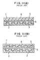
- Fig. 11 schematically shows a cross section of an optical disc formed of two pieces of discoid resin substrates (a first resin substrate 2 and a second resin substrate 6) which are bonded to each other, wherein Fig. 11(A) shows the optical disc having information signals which are stored in one of the resin substrates and Fig. 11(B) shows the optical disc having information signals which are stored in both resin substrates.
- optical disc having information signals which are stored in one of the resin substrates.
- the first resin substrate 2 is formed of transparent polycarbonate resin by an infection molding machine. Bits representing binary unit of information, i.e., information signals such as voice are stored in one surface of the first resin substrate 2.
- a reflecting film 3 formed of aluminum or the like is formed on the surface on which information signals are stored (hereinafter referred to as signal surface), and a protecting film 4 such as an adhesive is provided on the reflecting film 3 for preventing the signal surface from being damaged.
- the second resin substrate formed of transparent polycarbonate which is the same as the first resin substrate 2 is bonded to the signal surface of the first resin substrate 2 by way of an adhesive 5.
- Such a method corresponds to the preamble of claim 1 and is disclosed in JP-A-61 139956.
- firstly the first resin substrate 2 is placed on the placing platform 7, secondly the adhesives having flowability, e.g., ultra violet curing resin is coated on the first resin substrate 2, thirdly the second resin substrate 6 is placed on the first resin substrate 2 and they are laid on each other, fourthly the first resin substrate 2 and second resin substrate 6 are rotated while they are laid on each other so as to uniformly extend or spread the adhesive which is interposed therebetween.
- the resin 5 is scattered when it is spread, and air confined in the adhesive 5 interposed between the first and resin substrates is expelled outside.
- the adhesive 5 which is uniformly spread between the first and second resin substrates, is cured while it is irradiated by UV rays. As a result, the bonding of the first resin substrate 2 and second resin substrate 6 is completed.
- the adhesive when the adhesive is spread owing to the rotation of the first and second resin substrates, it is spread sufficiently at a region having the signal surface due to the centrifugal force but it is not sufficiently extended at a region close to central holes of the first and second resin substrates having no signal surface and air remains therebetween, leading to short of the spreading of the adhesive 5.
- the adhesive has to be extended thoroughly and uniformly between the first and second resin substrates having no signal surface at the centers thereof. The reason is that a spot is formed on the region having no signal surface when the adhesive is cured in a later step, leading to deterioration of beauty thereof and also leading to the lowering of strength at the bonding surfaces at the central holes thereof.
- JP-A-01 101124 discloses a placing platform with a boss having suction means. Said placing platform is not provided for bonding together two substrates, but rather for holding a stamper which transfers the information pattern to a photopolymer.
- the present invention has been made to solve the aforementioned problem.
- the inventors of the prevent invention have devoted themselves to a research and they discovered that the adhesive was efficiently spread at the centers of the first and second resin substrates when negative pressure acts upon the centers thereof in a spreading step.
- the inventors completed the invention based on this discovery.
- It is a first aspect of the invention to provide a method of manufacturing an optical disc comprising the steps of coating an adhesive onto a first resin substrate, placing a second resin substrate on the first resin substrate, then spreading the adhesive by rotating the first and second resin substrates at high speed, thereafter curing the adhesive thereby bonding the first and second resin substrates, characterized by sucking the adhesive from central holes of the first and second resin substrates during rotating to facilitate spreading of the adhesive at the central holes thereof.
- the adhesive is sucked by a boss having suction ports at its outer periphery and inserted into the central holes of the first and second resin substrates.
- the adhesive is sucked by introducing fresh air from the upper and lower surfaces of the first and second resin substrates through a gap defined between the outer periphery of the boss and the central holes of the first and second resin substrates.
- suction strength is so large as to stop the adhesive at liquid stop grooves defined in both resin substrates.
- said suction means comprises suction ports, a suction passage and a suction source, said suction passage communicating between the suction ports and said suction source.
- the boss is detachably attached to the placing platform.
- a dome body is arranged around the placing platform so as to prevent the adhesive from being scattered around the placing platform.
- a recess is provided on the placing platform around the boss so as to communicate with the atomosphere.
- the adhesive is sucked through the central holes of both resin substrates, thereby facilitating the spreading of the adhesive at the central holes thereof.
- a method of manufacturing an optical disc generally comprises a step of forming a first resin substrate by an injection molding machine using a stamper of an optical disc manufactured in a mastering step, a step of forming a reflecting film and a protecting film on a signal surface of the first resin substrate, and a step of bonding a second resin substrate on the signal surface of the first resin substrate.
- the method of manufacturing the optical disc according to the present invention belongs to the step of bonding the second resin substrate on the first resin substrate, particularly, it relates to a step of spreading the adhesive in the step of bonding the first and second resin substrates.
- step (1) a first resin substrate 2 having a signal surface on which a reflecting film and a protecting film are coated is uniformly sucked to and held by a placing platform 7.
- step (2) the UV curing resin 5 is discharged through the discharge port of a discharge nozzle 8 while the placing platform 7 on which the first resin substrate 2 is placed is rotated at low speed.
- the UV curing resin 5 is coated on the first resin substrate 2 when it is discharged through the discharge nozzle 8, a circular track is drawn on the first resin substrate 2.
- step (3) a transparent second resin substrate 6 is placed on the UV curing resin 5 by a robotic hand, etc. upon completion of the coating UV curing resin 5.
- the second resin substrate 6 sequentially contacts the UV curing resin 5 while directing from the center to the periphery thereof when the second resin substrate 6 is placed on the UV curing resin 5.
- step (4) the UV curing resin 5 interposed between the first resin substrate 2 and second resin substrate 6 is spread so as to be extended uniformly therebetween, and air interposed between both resin substrates and bubbles contained in the UV curing resin 5 are respectively expelled.
- the placing platform 7 is rotated at high speed (normally the number of rotation is more than several thousands rpm and rotating time is about several seconds) while the first resin substrate 2 and second resin substrate 6 are laid on each other.
- step (5) the UV curing resin 5 is irradiated by UV rays to be cured while the first resin substrate 2 and second resin substrate 6, which are laid on and bonded to each other to be integrated with each other, are rotated (e.g., normally about several rpm) or not rotated.
- both resin substrates 2 and 6 are directly irradiated by the UV curing resin 5 emitted from a UV light source 12 from the upper or lower direction thereof or from both upper and lower directions thereof.
- the second resin substrate 6 is irradiated by UV rays from the upper direction thereof.
- the UV light source 12 having a reflecting mirror at the back thereof is used to perform the irradiation effectively.
- a reflecting mirror is disposed aslant (e.g., 45 degrees) around the bonded first and second resin substrates. Accordingly both resin substrates can be effectively heated and cured at the peripheries thereof.
- the adhesive resin When the adhesive resin is of a hot melt type, it is cured without being irradiated by UV rays.
- step (5) there is taken a step of moving both resin substrates at constant speed through UV rays region which is emitted from the UV light source 12. As a result, the step of bonding both resin substrates is completed, thereby manufacturing the optical disc comprising two pieces of integrated resin substrates.
- Fig. 1 is a cross sectional view showing a state where both resin substrates, which are bonded to each other by an adhesive, e.g., UV curing resin, are placed on a placing platform.
- Fig. 2 is a view showing a state where a UV curing resin is sucked through a boss which is inserted into central holes of both resin substrates, and
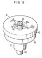
- Fig. 3 is an entire perspective view of the placing platform.
- the placing platform 7 comprises a placing body 16, a table 15 attached onto the placing body 16 and a boss 10 to be attached to the placing body 16.
- the entire placing platform 7 is rotatable by a rotary shaft 20 which extends to the placing body 16 and is integrated with the placing platform 7.
- the rotary shaft 20 is supported by a fixed shaft 21 having a bearing therein.
- the placing body 16 has a suction passage 17 at the center thereof, and the suction passage 17 is connected to a suction source, not shown, through the interior of the rotary shaft 20 extended to the placing body 16.
- the placing body 16 has a plurality of communication holes 19 which communicate with the atmosphere.
- the table 15 is fixed to the placing body 16 when the former is engaged with the latter from the upper portion of the latter.
- the table 15 has a flat seat surface on which both resin substrates 1 are placed and also has a large diameter through hole 18 which communicates with the communication holes 19.
- Suction holes, not shown, are provided on the seat surface of the table 15 to permit the first and second resin substrates not to move on the table 15.
- the boss 10 is engaged with and fixed to the upper end of the suction passage 17 provided at the center of the placing body 16. At this time, the boss 10 is bonded to the placing body 16 using an adhesive such as a paste to maintain hermeticity with respect to the placing body 16. Accordingly, the boss 10 can be easily detachable when replaceable with another one.
- the top of the boss 10 is slightly projecting from the seat surface of the table 15.
- the projected boss 10 is inserted into central holes 11 defined in both resin substrates 1.
- the boss 10 has a sucking function, and hence it has suction means including a ring groove 10a, etc.
- the suction means comprises the ring groove 10a defined in the outer circumference of the boss 10, a plurality of suction ports 10b provided on the bottom of the ring groove 10a, and a suction passage 14 formed inside the boss 10, a suction passage 17 provided inside the placing body 16, and a suction source, not shown, to which the suction passage 17 is connected by way of the rotary shaft 20.
- Suction operation can be performed through the ring groove 10a of the boss 10 in a state where the boss 10 is inserted into the central holes 11 of both resin substrates 1.
- a recessed space is formed by the large diameter penetration hole 18 at the periphery of the boss 10.
- the reason why the recessed space is defined is that fresh air is introduced through the lower surfaces of both resin substrates 1 when the adhesive 5 is sucked through the ring groove 10a after both resin substrates 1 are placed on the seat surface of the table 15.
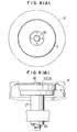
- a circular dome body X is disposed around the placing platform 7 for receiving the scattered adhesive 5 to prevent it from being scattered outward since the adhesive 5 is scattered outward from both resin substrates 1 owing to the centrifugal force in a spreading step, described later.
- Fig. 6 shows a relation between the placing platform 7 and the dome body X, wherein Fig. 6(A) is a plan view and Fig. 6(B) is a side view.
- the spreading step facilitates the spreading of the adhesive 5, e.g., the UV curing resin 5 interposed between both resin substrates 1 in a state where the placing platform 7 is rotated at high speed so as to extend the UV curing resin 5 thoroughly and uniformly, and also expels air contained in bubbles inside the UV curing resin 5.
- the adhesive e.g., the UV curing resin 5 interposed between both resin substrates 1 in a state where the placing platform 7 is rotated at high speed so as to extend the UV curing resin 5 thoroughly and uniformly, and also expels air contained in bubbles inside the UV curing resin 5.
- the second resin substrate 6 is placed on the first resin substrate 2, which was previously placed on the placing platform 7, by way of the UV curing resin 5.
- the UV curing resin 5 is prevented from being scattered by the dome body X which is disposed around the placing platform 7.
- the UV curing resin 5 received by the dome body X is collected by way of a discharge port as shown by arrows.
- the suction source e.g., a vacuums suction device
- the suction source is operated at roughly the same time when the placing platform 7 is rotated at high speed, ambient air around the ring groove 10a is sucked sequentially through a plurality of suction ports 10b and the suction passages 14 and 17.
- the UV curing resin 5 interposed between both resin substrates 1 as shown in Fig. 2 is sequentially sucked through the ring groove 10a, a plurality of suction ports 10b, and the suction passages 14 and 17.
- the adhesive i.e., UV curing resin 5 to be used in the spreading step has constant flowability.
- the placing platform 7 is actuated so as to be rotated at high speed and at the same time the suction source is operated so that the suction operation starts through the ring groove 10a of the boss 10 (see to Fig. 4(A)).
- the UV curing resin 5 interposed between both resin substrates 1 is spread and at the same time it flows toward the central holes 11 by this suction operation.
- the UV curing resin 5 which exists at a portion close to the central holes 11 of both resin substrates 1 represents irregular spot comprising an air portion and a resin portion when viewed from the above as shown in Fig. 5(A).
- Fig. 5 shows, for convenience of explanation, a state where the second resin substrate 6 is transparent so that the UV curing resin 5 is seen through the second resin substrate 6.
- the suction operation is performed, the UV curing resin 5 is gradually sucked out from the bonding surfaces of both resin substrates 1 at the central holes 11 so that the UV curing resin 5 is extended toward the entire central portion (see to Fig. 4 (B)) .
- the UV curing resin 5 is sucked and leaked out from the bonding surfaces of resin substrates 1 at the central holes 11 flows upward or downward together with fresh air as shown in Fig. 2, and hence it is further sucked from the ring groove 10a of the boss 10 through the plurality of suction ports 10b.
- the UV curing resin 5 which exists at a portion close to the central holes of both resin substrates 1 is changed to a state where the spot is disappeared and the UV curing resin 5 is thoroughly and uniformly extended as shown in Fig. 5(B).
- the rotation of the placing platform and the suction of the UV curing resin 5 are stopped, thereby completing the spreading step.
- the UV curing resin 5 is strongly sucked until it is expelled outward from the central holes 11, and the expelled UV curing resin 5 is taken in the boss 10.
- the suction operation through the boss 10 is needed to be changed in its manner depending on the kinds of optical discs.
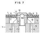
- the suction force can be adjusted until the UV curing resin 5 stops at the liquid stop grooves P.
- Fig. 7 shows a state of suction at that time when the UV curing resin 5 is not taken in the boss 10 even if it is sucked through the boss 10.
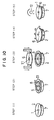
- the UV curing resin 5 is sucked in a direction of an arrow, then it stops at the liquid stop grooves P as shown in Fig. 8(B). As a result, the UV curing resin 5 is formed like a ring along the liquid stop grooves P at the inner boundary thereof.
- Fig. 9 shows, for convenience of explanation, a state where the second resin substrate 6 is transparent so that the UV curing resin 5 is seen through the second resin substrate 6.
- the spreading of the UV curing resin 5 can be changed to any degree.
- the placing platform is structured by combining separate placing body and table, but they can be formed integrally. Further, the shape of the boss can be changed to some extent so long as it has sucking function and can be attached to the placing platform.
- the adhesive to be used in the present invention does not care the kinds thereof if it can bond the first and second resin substrates.
- information signals can be stored in the following cases, namely, the first case is that information signals are stored in the first resin substrate and they are not stored in the second resin substrate, the second case is the information signals are stored in the second resin substrate and they are not stored in the first resin substrate, and the third case is that the information signals are stored in both resin substrates.
- the present invention it is possible to extend the adhesive thoroughly and uniformly between the entire bonding surfaces of both resin substrates, and also possible to expel bubbles interposed between the bonding surfaces outward.
- the adhesive can be uniformly spread at a portion close to the central hole of the optical disc, and it is possible to manufacture the optical disc of high quality.
- the optical disc thus manufactured is improved in beauty at the portion close to the central hole thereof and is strong in its bonding strength.
Landscapes
- Engineering & Computer Science (AREA)
- Mechanical Engineering (AREA)
- Physics & Mathematics (AREA)
- Electromagnetism (AREA)
- Health & Medical Sciences (AREA)
- Toxicology (AREA)
- Manufacturing & Machinery (AREA)
- Chemical & Material Sciences (AREA)
- Chemical Kinetics & Catalysis (AREA)
- General Chemical & Material Sciences (AREA)
- Manufacturing Optical Record Carriers (AREA)
Claims (9)
- Verfahren zur Herstellung einer optischen Platte (1), das die Schritte umfaßt: Auftragen eines Klebstoffes (5) auf ein erstes Harzsubstrat (2), Plazieren eines zweiten Harzsubstrats (6) auf dem ersten Harzsubstrat (2), danach Verteilen des Klebstoffes (5) durch Drehen der ersten und zweiten Harzsubstrate (2, 6) mit hoher Geschwindigkeit, nachfolgend Aushärten des Klebstoffes (5), wodurch die ersten und zweiten Harzsubstrate (2, 6) verbunden werden, gekennzeichnet durch Saugen des Klebstoffes (5) von zentralen Löchern (11) der ersten und zweiten Harzsubstrate (2, 6) während des Drehens, um ein Verteilen des Klebstoffes (5) an den zentralen Löchern (11) derselben zu erleichtern.
- Verfahren nach Anspruch 1, dadurch gekennzeichnet, daß der Klebstoff (5) von einem Vorsprung (10) gesaugt wird, der Saugöffnungen (10b) an seinem Außenumfang aufweist und in die zentralen Löcher (11) der ersten und zweiten Harzsubstrate (2, 6) eingesetzt ist.
- Verfahren nach Anspruch 2, dadurch gekennzeichnet, daß der Klebstoff (5) durch Einleiten von frischer Luft von den oberen und unteren Flächen der ersten und zweiten Harzsubstrate (2, 6) durch einen zwischen dem Außenumfang des Vorsprungs (10) und den zentralen Löchern (11) der ersten und zweiten Harzsubstrate (2, 6) gebildeten Spalt gesaugt wird.
- Verfahren nach Anspruch 1, 2 oder 3, dadurch gekennzeichnet, daß die Saugstärke so groß ist, um den Klebstoff (5) an in beiden Harzsubstraten (2, 6) definierten Flüssigkeitsstopnuten (P) zu stoppen.
- Plazierplattform (7) für eine optische Platte (1), die zur Verwendung mit dem Plattenherstellverfahren nach Anspruch 1 geeignet ist, worin die Plazierplattform (7) einen Vorsprung (10) aufweist, der mit einem Saugmittel versehen ist, das zum Erleichtern des Verteilens von Klebstoff (5) an den zentralen Löchern (11) der Plattensubstrate (2, 6) durch Saugen des Klebstoffes von den zentralen Löchern geeignet ist.
- Plazierplattform (7) nach Anspruch 5, dadurch gekennzeichnet, daß das Saugmittel Saugöffnungen (10b), einen Saugdurchgang (17) und eine Saugquelle umfaßt, wobei der Saugdurchgang (17) mit den Saugöffnungen (10b) und der Saugquelle in Verbindung steht.
- Plazierplattform nach Anspruch 5 oder 6, dadurch gekennzeichnet, daß der Vorsprung (10) lösbar an der Plazierplattform (7) angebracht ist.
- Plazierplattform nach Anspruch 5 oder 6, ferner umfassend einen Domkörper (X), wobei der Domkörper um die Plazierplattform (7) herum angeordnet ist.
- Plazierplattform nach Anspruch 5 oder 6, dadurch gekennzeichnet, daß eine Ausnehmung auf der Plazierplattform (7) um den Vorsprung (10) herum vorgesehen ist, um mit der Atmosphäre in Verbindung zu stehen.
Applications Claiming Priority (3)
| Application Number | Priority Date | Filing Date | Title |
|---|---|---|---|
| JP14523195 | 1995-05-20 | ||
| JP145231/95 | 1995-05-20 | ||
| JP14523195 | 1995-05-20 |
Publications (2)
| Publication Number | Publication Date |
|---|---|
| EP0744739A1 EP0744739A1 (de) | 1996-11-27 |
| EP0744739B1 true EP0744739B1 (de) | 2002-01-02 |
Family
ID=15380378
Family Applications (1)
| Application Number | Title | Priority Date | Filing Date |
|---|---|---|---|
| EP96107914A Expired - Lifetime EP0744739B1 (de) | 1995-05-20 | 1996-05-17 | Verfahren zur Herstellung einer optischen Platte und dazu verwendete Plattform |
Country Status (3)
| Country | Link |
|---|---|
| US (1) | US5744193A (de) |
| EP (1) | EP0744739B1 (de) |
| DE (1) | DE69618275T2 (de) |
Families Citing this family (37)
| Publication number | Priority date | Publication date | Assignee | Title |
|---|---|---|---|---|
| US5681634A (en) * | 1995-02-15 | 1997-10-28 | Matsushita Electric Industrial Co., Ltd. | Optical information medium, and method and apparatus for fabricating the same |
| USRE39412E1 (en) * | 1995-02-15 | 2006-11-28 | Matsushita Electric Industrial Co., Ltd. | Optical information medium, and method and apparatus for fabricating the same |
| EP0773372B1 (de) * | 1995-10-13 | 2004-12-15 | Kitano Engineering Co., Ltd. | Drehender Haltetisch, mit Stift, zum darauf Festhalten und Drehen einer Informationsscheibe |
| US5951806A (en) * | 1995-11-30 | 1999-09-14 | Kitano Engineering Co., Ltd. | Method of manufacturing a storage disc |
| TW330288B (en) | 1996-04-19 | 1998-04-21 | Matsushita Denki Sanguo Kk | Bonding method and apparatus for optical disk |
| JPH09320159A (ja) * | 1996-05-27 | 1997-12-12 | Mitsubishi Electric Corp | 貼り合せディスクのターンテーブル装置および貼り合せディスク |
| EP0833315B1 (de) * | 1996-07-31 | 2004-11-24 | Kitano Engineering Co., Ltd. | Verfahren zum Korrigieren von der ungleichen Position einer Informationsscheibe |
| DE19651423C2 (de) * | 1996-12-11 | 1999-11-25 | Singulus Technologies Ag | Vorrichtung und Verfahren zum Verkleben von zwei Substratteilen zu einem Substrat, insbesondere zu einem optischen Datenträger (CD) |
| EP0866450B1 (de) * | 1997-03-17 | 1999-06-30 | TAPEMATIC S.p.A. | Gerät und Verfahren zum Kleben von Plattenhälften zur Herstellung von optischen Datenspeicherplatten |
| JPH10275446A (ja) * | 1997-03-31 | 1998-10-13 | Takashi Shigetomi | 記憶媒体とその製造方法 |
| DE19718471A1 (de) * | 1997-04-30 | 1998-11-05 | Steag Hamatech Gmbh Machines | Verfahren und Vorrichtung zum Verkleben von zwei Substraten |
| JP3958802B2 (ja) * | 1997-05-30 | 2007-08-15 | 松下電器産業株式会社 | 光ディスクの製造方法および装置 |
| US5932042A (en) * | 1997-06-19 | 1999-08-03 | Gensel; Lewis | Compact disc curing assembly line with deforming to a predetermined curvature prior to complete cure |
| US6077349A (en) * | 1997-08-20 | 2000-06-20 | Sony Corporation | Method and apparatus for manufacturing disc-shaped recording medium |
| EP0908876A3 (de) * | 1997-10-08 | 2002-02-13 | Leybold Systems GmbH | Verfahren zum Verkleben eines flachen, kreisscheibenförmigen ersten Substrats aus einem Kunststoff mit einem ebensolchen zweiten Substrat zu einer digital video disc und Vorrichtung zur Durchführung des Verfahrens |
| DE19748699A1 (de) * | 1997-11-04 | 1999-05-06 | Data Disc Robots Gmbh | Verfahren zum Verkleben von Datenträgerplatten |
| US6254809B1 (en) | 1998-05-19 | 2001-07-03 | Steag Hamatech, Inc. | System and method for curing a resin disposed between a top and bottom substrate with thermal management |
| US6106657A (en) * | 1998-05-19 | 2000-08-22 | First Light Technology, Inc. | System and method for dispensing a resin between substrates of a bonded storage disk |
| US6352612B1 (en) | 1998-05-19 | 2002-03-05 | Steag Hamatech, Inc. | System for forming bonded storage disks with low power light assembly |
| US6103039A (en) * | 1997-11-12 | 2000-08-15 | First Light Technology, Inc. | System and method for thermally manipulating a combination of a top and bottom substrate before a curing operation |
| WO1999024239A1 (en) * | 1997-11-12 | 1999-05-20 | First Light Technology, Inc. | System and method for distributing a resin disposed between a top substrate and a bottom substrate |
| US6214412B1 (en) | 1998-05-19 | 2001-04-10 | First Light Technologies, Inc. | System and method for distributing a resin disposed between a top substrate and a bottom substrate |
| US6098272A (en) * | 1998-05-19 | 2000-08-08 | First Light Technology, Inc. | System for maintaining concentricity of a combination of a top and bottom substrate during the assembly of a bonded storage disk |
| DE19755088A1 (de) * | 1997-12-11 | 1999-06-17 | Daimler Chrysler Ag | Kalibriervorrichtung zum Verkleben von Scheiben |
| JP3581246B2 (ja) * | 1997-12-17 | 2004-10-27 | パイオニア株式会社 | 貼り合わせ型光ディスクの製造方法 |
| SE511641C2 (sv) * | 1998-02-24 | 1999-11-01 | Toolex Alpha Ab | Förfarande för sammanlimning av optiska skivsubstrat |
| US6020042A (en) | 1998-10-14 | 2000-02-01 | First Light Technology, Inc. | Substrate design for bonded storage disks and method of making same |
| JP2000160107A (ja) * | 1998-11-30 | 2000-06-13 | Dainippon Printing Co Ltd | 薄板で被覆された基板の製造方法 |
| WO2000054265A1 (fr) * | 1999-03-10 | 2000-09-14 | Global Machinery Co., Ltd | Procede et appareil d'assemblage de disques optiques |
| US6355124B1 (en) * | 1999-05-24 | 2002-03-12 | Bmc Vision-Ease Lens, Inc. | Lamination apparatus and process |
| JP2001209980A (ja) * | 2000-01-26 | 2001-08-03 | Matsushita Electric Ind Co Ltd | 光学的情報記録媒体の製造方法および製造装置 |
| DE10063666C1 (de) * | 2000-12-20 | 2002-04-11 | Steag Hamatech Ag | Verfahren und Vorrichtung zum Zusammenfügen von Substraten |
| JP3559535B2 (ja) * | 2001-05-16 | 2004-09-02 | 北野エンジニアリング株式会社 | 光ディスク接着剤硬化装置 |
| JP2003067991A (ja) * | 2001-06-07 | 2003-03-07 | Fuji Photo Film Co Ltd | 光ディスクの製造方法及びディスク積層体の搬送方法 |
| JP3986383B2 (ja) | 2001-08-31 | 2007-10-03 | 株式会社リコー | 板状体の製造方法及び製造装置 |
| JP4325276B2 (ja) * | 2003-05-28 | 2009-09-02 | コニカミノルタエムジー株式会社 | ホログラフィック記録メディア及びその製造方法 |
| CN100431023C (zh) * | 2004-09-23 | 2008-11-05 | 精碟科技股份有限公司 | 光信息储存媒体的制造装置 |
Family Cites Families (7)
| Publication number | Priority date | Publication date | Assignee | Title |
|---|---|---|---|---|
| JPS61139956A (ja) * | 1984-12-11 | 1986-06-27 | Matsushita Electric Ind Co Ltd | 情報担体ディスクの製造方法 |
| US4877475A (en) * | 1984-11-01 | 1989-10-31 | Matsushita Electric Industrial Co., Ltd. | Method for producing information storage disk |
| DE3732113C1 (de) * | 1987-09-24 | 1988-10-20 | Convac Gmbh | Einrichtung zur Inline-Belackung von Compact-Discs |
| JPH01101124A (ja) * | 1987-10-15 | 1989-04-19 | Pioneer Electron Corp | 光ディスク製造装置 |
| JPH0626823B2 (ja) * | 1987-10-15 | 1994-04-13 | パイオニア株式会社 | 光ディスク製造装置 |
| JPH0453012A (ja) * | 1990-06-20 | 1992-02-20 | Fujitsu Ltd | 薄膜磁気ヘッドの製造方法 |
| JPH0836786A (ja) * | 1994-07-21 | 1996-02-06 | Nikon Corp | 光記録媒体の製造方法 |
-
1996
- 1996-05-17 EP EP96107914A patent/EP0744739B1/de not_active Expired - Lifetime
- 1996-05-17 DE DE69618275T patent/DE69618275T2/de not_active Expired - Fee Related
- 1996-05-17 US US08/650,908 patent/US5744193A/en not_active Expired - Fee Related
Also Published As
| Publication number | Publication date |
|---|---|
| DE69618275D1 (de) | 2002-02-07 |
| DE69618275T2 (de) | 2002-06-13 |
| US5744193A (en) | 1998-04-28 |
| EP0744739A1 (de) | 1996-11-27 |
Similar Documents
| Publication | Publication Date | Title |
|---|---|---|
| US5744193A (en) | Method of manufacturing an optical disc and a placing platform to be used by the same | |
| EP0833315B1 (de) | Verfahren zum Korrigieren von der ungleichen Position einer Informationsscheibe | |
| EP0928243B1 (de) | Verfahren und gerät zum zusammenkleben von scheibenelementen | |
| EP0756274B1 (de) | Struktur einer zusammengesetzten optischen Platte | |
| EP1339054A1 (de) | Optisches aufzeichnungsmedium und verfahren zu seiner herstellung und spritzgussmaschine | |
| KR101096348B1 (ko) | 광학 기록 매체 및 그 제조 방법 | |
| US5843257A (en) | Method of developing an adhesive and a rotary holding table for carrying out the same method | |
| EP0773372B1 (de) | Drehender Haltetisch, mit Stift, zum darauf Festhalten und Drehen einer Informationsscheibe | |
| US6383326B1 (en) | Method for glueing together disc elements | |
| US5800670A (en) | Spreader of an optical disc | |
| US5951806A (en) | Method of manufacturing a storage disc | |
| JPH08293131A (ja) | 光ディスクの製造方法 | |
| US6503423B1 (en) | Method of and apparatus for curing an optical disc | |
| EP1450360A1 (de) | Verfahren und einrichtung zur herstellung eines optischen aufzeichnungsmediums | |
| JPH0944917A (ja) | 光ディスクの製造方法およびその製造方法に使用される載置基台 | |
| JP4084551B2 (ja) | 光ディスクの製造方法 | |
| JP3703230B2 (ja) | 保持台から記憶ディスクを取り上げる方法 | |
| JP3593599B2 (ja) | 記憶ディスクにおけるバリの処理方法及びその装置 | |
| US6702920B2 (en) | Production method of and production apparatus for optical recording disc | |
| JP3187725B2 (ja) | 記憶ディスクの回転保持台 | |
| JP3495145B2 (ja) | 光ディスクの端部処理方法及びその装置 | |
| JP3628816B2 (ja) | 記憶ディスクの保持台及びそのボス体 | |
| JP2002042383A (ja) | 光ディスク貼合方法及び貼合装置 | |
| JP3020594B2 (ja) | ディスクの成形方法とその成形装置 | |
| JPH09161328A (ja) | 記憶ディスクにおける接着剤の延展方法 |
Legal Events
| Date | Code | Title | Description |
|---|---|---|---|
| PUAI | Public reference made under article 153(3) epc to a published international application that has entered the european phase |
Free format text: ORIGINAL CODE: 0009012 |
|
| AK | Designated contracting states |
Kind code of ref document: A1 Designated state(s): DE FR GB NL |
|
| 17P | Request for examination filed |
Effective date: 19970429 |
|
| 17Q | First examination report despatched |
Effective date: 19991122 |
|
| GRAG | Despatch of communication of intention to grant |
Free format text: ORIGINAL CODE: EPIDOS AGRA |
|
| GRAG | Despatch of communication of intention to grant |
Free format text: ORIGINAL CODE: EPIDOS AGRA |
|
| GRAH | Despatch of communication of intention to grant a patent |
Free format text: ORIGINAL CODE: EPIDOS IGRA |
|
| GRAH | Despatch of communication of intention to grant a patent |
Free format text: ORIGINAL CODE: EPIDOS IGRA |
|
| GRAA | (expected) grant |
Free format text: ORIGINAL CODE: 0009210 |
|
| REG | Reference to a national code |
Ref country code: GB Ref legal event code: IF02 |
|
| AK | Designated contracting states |
Kind code of ref document: B1 Designated state(s): DE FR GB NL |
|
| PG25 | Lapsed in a contracting state [announced via postgrant information from national office to epo] |
Ref country code: NL Free format text: LAPSE BECAUSE OF FAILURE TO SUBMIT A TRANSLATION OF THE DESCRIPTION OR TO PAY THE FEE WITHIN THE PRESCRIBED TIME-LIMIT Effective date: 20020102 |
|
| REF | Corresponds to: |
Ref document number: 69618275 Country of ref document: DE Date of ref document: 20020207 |
|
| ET | Fr: translation filed | ||
| NLV1 | Nl: lapsed or annulled due to failure to fulfill the requirements of art. 29p and 29m of the patents act | ||
| PLBE | No opposition filed within time limit |
Free format text: ORIGINAL CODE: 0009261 |
|
| STAA | Information on the status of an ep patent application or granted ep patent |
Free format text: STATUS: NO OPPOSITION FILED WITHIN TIME LIMIT |
|
| 26N | No opposition filed | ||
| NLV1 | Nl: lapsed or annulled due to failure to fulfill the requirements of art. 29p and 29m of the patents act | ||
| PGFP | Annual fee paid to national office [announced via postgrant information from national office to epo] |
Ref country code: DE Payment date: 20060511 Year of fee payment: 11 |
|
| PGFP | Annual fee paid to national office [announced via postgrant information from national office to epo] |
Ref country code: FR Payment date: 20060515 Year of fee payment: 11 |
|
| PGFP | Annual fee paid to national office [announced via postgrant information from national office to epo] |
Ref country code: GB Payment date: 20060517 Year of fee payment: 11 |
|
| REG | Reference to a national code |
Ref country code: GB Ref legal event code: 732E |
|
| REG | Reference to a national code |
Ref country code: FR Ref legal event code: TP |
|
| GBPC | Gb: european patent ceased through non-payment of renewal fee |
Effective date: 20070517 |
|
| REG | Reference to a national code |
Ref country code: FR Ref legal event code: ST Effective date: 20080131 |
|
| PG25 | Lapsed in a contracting state [announced via postgrant information from national office to epo] |
Ref country code: DE Free format text: LAPSE BECAUSE OF NON-PAYMENT OF DUE FEES Effective date: 20071201 |
|
| PG25 | Lapsed in a contracting state [announced via postgrant information from national office to epo] |
Ref country code: GB Free format text: LAPSE BECAUSE OF NON-PAYMENT OF DUE FEES Effective date: 20070517 |
|
| PG25 | Lapsed in a contracting state [announced via postgrant information from national office to epo] |
Ref country code: FR Free format text: LAPSE BECAUSE OF NON-PAYMENT OF DUE FEES Effective date: 20070531 |