EP0744360A1 - Müllsammelbehälter und Verfahren zu seiner Verwendung - Google Patents
Müllsammelbehälter und Verfahren zu seiner Verwendung Download PDFInfo
- Publication number
- EP0744360A1 EP0744360A1 EP96401121A EP96401121A EP0744360A1 EP 0744360 A1 EP0744360 A1 EP 0744360A1 EP 96401121 A EP96401121 A EP 96401121A EP 96401121 A EP96401121 A EP 96401121A EP 0744360 A1 EP0744360 A1 EP 0744360A1
- Authority
- EP
- European Patent Office
- Prior art keywords
- container
- container according
- flaps
- walls
- wall
- Prior art date
- Legal status (The legal status is an assumption and is not a legal conclusion. Google has not performed a legal analysis and makes no representation as to the accuracy of the status listed.)
- Granted
Links
Images

Classifications
-
- B—PERFORMING OPERATIONS; TRANSPORTING
- B65—CONVEYING; PACKING; STORING; HANDLING THIN OR FILAMENTARY MATERIAL
- B65F—GATHERING OR REMOVAL OF DOMESTIC OR LIKE REFUSE
- B65F1/00—Refuse receptacles; Accessories therefor
- B65F1/02—Refuse receptacles; Accessories therefor without removable inserts
-
- B—PERFORMING OPERATIONS; TRANSPORTING
- B65—CONVEYING; PACKING; STORING; HANDLING THIN OR FILAMENTARY MATERIAL
- B65F—GATHERING OR REMOVAL OF DOMESTIC OR LIKE REFUSE
- B65F1/00—Refuse receptacles; Accessories therefor
- B65F1/12—Refuse receptacles; Accessories therefor with devices facilitating emptying
- B65F1/122—Features allowing the receptacle to be lifted and subsequently tipped by associated means on a vehicle
-
- B—PERFORMING OPERATIONS; TRANSPORTING
- B65—CONVEYING; PACKING; STORING; HANDLING THIN OR FILAMENTARY MATERIAL
- B65F—GATHERING OR REMOVAL OF DOMESTIC OR LIKE REFUSE
- B65F1/00—Refuse receptacles; Accessories therefor
- B65F1/14—Other constructional features; Accessories
- B65F1/1468—Means for facilitating the transport of the receptacle, e.g. wheels, rolls
-
- B—PERFORMING OPERATIONS; TRANSPORTING
- B65—CONVEYING; PACKING; STORING; HANDLING THIN OR FILAMENTARY MATERIAL
- B65F—GATHERING OR REMOVAL OF DOMESTIC OR LIKE REFUSE
- B65F2220/00—Properties of refuse receptacles
- B65F2220/106—Collapsible
- B65F2220/1063—Collapsible foldable
Definitions
- the present invention relates to a container, such as a rolling bin, for collecting waste.
- Containers which have a rear wall, a front wall, side walls and a bottom wall defining a tank of generally parallelepiped shape, usually provided at its lower part with wheels for the displacement by rolling of the container and provided on its front wall hooking means for lifting, tilting and emptying the container by a collection vehicle.
- Such containers can collect a volume of waste which is typically greater than a hundred liters.
- the size of an empty container according to the invention is thus reduced compared to that of a known non-collapsible container, and the storage of containers awaiting their filling is facilitated.
- each side wall has two flaps hinged together by an edge and hinged respectively by the edge opposite the rear wall and the front wall.
- the container further comprises at least one member for holding the container in the unfolded position.
- At least one of the holding members is shaped to be able to engage from above with the front and rear walls when the container is folded, to keep it in this state.
- each holding member is provided with a handle.
- the holding members of the container in the unfolded position can advantageously be used to help the user fold or unfold the container without the risk of it getting dirty or injuring itself during this operation, for example by pinching the fingers between the flaps of the side walls.
- the holding members are of particularly reliable operation, compatible with the severe conditions of use to which the containers are subjected.
- each holding member advantageously comprises an elongated body able to come into engagement with the upper edges of the two associated flaps to hold the latter in line with one another.
- This elongated body advantageously has at its longitudinal ends lugs projecting downwards, capable of engaging with the upper edges of the rear and front walls to maintain the container in the folded state.
- each holding member is returned by an elastic return means in its locked position.
- each holding member is integral with a rod guided to slide by at least one of the associated flaps, this rod preferably being situated in the extension of a material articulation axis connecting the two flaps.
- the elastic return means preferably consists of a spring located in the extension of the material hinge axis of the two flaps.
- This spring is advantageously housed in a housing comprising a lower part and an upper part capable of sliding one inside the other and integral respectively with the rod of the holding member and one of the flaps, said spring working in compression to urge said spacing parts.
- the container comprises at least one holding member constituted by a hinged frame on the upper part of one of the front and rear walls and capable of engaging with the other of the front walls and rear to oppose the approximation of the latter and lock the container in the unfolded state.
- this frame is articulated at one end on the rear wall and it is able to snap into place at the opposite end in a clamp secured to the front wall.
- the container comprises at least one holding member articulated at one end on one of the front and rear walls and capable of engaging on top of the flaps of one of the side walls at least to keep them in the unfolded position.
- this holding member is constituted by a frame articulated at one end on one of the front and rear walls and capable of engaging from above on the two flaps of each side wall to keep them in the unfolded position.
- the bottom wall is provided with a control member such as a pedal, operable from outside the container, this control member making it possible to raise the bottom wall before the front and rear walls are brought together.
- a control member such as a pedal
- At least one of the front and rear walls is provided at the bottom with wheels.
- the bottom wall is pivotally mounted on an axle connecting said wheels and carried by said rear wall.
- the front and rear walls are each provided with two steerable wheels.
- At least one of the front and rear walls is provided with a hooking means for lifting, tilting and emptying the container by a collection vehicle.
- This attachment means is advantageously constituted by a rim extending the front wall towards the front and defining a groove open downwards.
- the rear wall is provided with at least one handle and a container closure cover, pivotally mounted on this handle.
- the invention also relates to a method for the implementation of a collection container according to the invention.
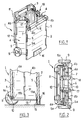
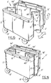
- the container 1 shown in Figures 1 to 3 has a front wall 2 and a rear wall 3 of rigid plastic.
- These walls 2, 3 are generally flat and parallel and have a substantially rectangular shape, of the same width and height, with long sides oriented vertically.
- Each component 4 a , 4 b has a generally rectangular shape with large sides oriented vertically.
- the flaps 4 a , 4 b of the same side panel are connected to each other in an articulated manner by a longitudinal edge and are connected in an articulated manner to the longitudinal edge opposite the rear wall 3 and the front wall 2 respectively.
- the flaps 4 a and 4 b are articulated on the front 2 and rear 3 walls by means of articulations 5 comprising metal pins 5 a or in other materials extending substantially over the entire height of the flaps in superimposed holes of the shutters and associated front or rear walls.
- the front wall 2 has at its upper edge a rim 6 projecting forward and defining a groove 7 open downward for the attachment, in a manner known per se, of the container 1 on a comb or a lifting bar d '' a waste collection vehicle.
- the rear wall 3 is provided at its lower end with a running gear for moving by rolling the container 1.
- This running gear has two wheels 9 carried by an axle 10 horizontally passing through the rear wall 3 and extending generally in parallel at the front wall 2.
- the rear wall 3 is provided above with a handle 11 extending obliquely towards the rear, in a manner known per se.
- a cover 12 is pivotally mounted on the handle 11 between an open position where it rests opposite the external face of the rear wall 3 and a closed position of the container in the deployed state, in which it rests on the upper edge of the front wall 2.
- the container 1 has a bottom wall 13 pivotally mounted on the axle 10. This bottom wall 13 is integral with a pedal 14 projecting from the rear of the container between the wheels 9 and allowing the user to lift the bottom wall 13 before folding the container 1.
- the bottom wall 13 rests at its end 13 a , opposite the articulation end 13 b on the rear wall 3, on a shoulder 15 of the front wall 2.
- this shoulder 15 is constituted by the inner edge of a profile 16 engaged on the lower edge of the front wall 2, as shown in FIGS. 1 and 3.
- the container 1 normally rests on the ground by the wheels 9 and by the base of the profile 16 and / or the lower edge of the front wall 2.
- the container 1 is provided at the front with a roller (not shown) pivotally mounted in the lower part of the front wall 2 and intended to facilitate the movement by rolling of the container 1.
- the front 2 and rear 3 walls, the flaps 4 a , 4 b and the bottom wall 13 are produced by extrusion / blow molding or by injection in high density polyethylene.
- the container 1 is provided with holding members 17, 18 able to keep it in the unfolded position, the flaps 4 a , 4 b of each side panel 4 then being located in the extension of one another.
- each holding member 17 or 18 is associated with a side panel 4 being mounted to move in the direction of the geometric axis of articulation of the two flaps 4 a , 4 b corresponding, between a locking position in which it engages with the two flaps to maintain them in the unfolded position in the extension of one another and a raised position allowing the folding of the flaps.
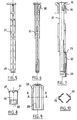
- Each retaining member 17, 18 comprises, as shown more particularly in Figure 4, an elongated body 19 open downwardly and shaped to be able to adapt come from above on the upper part of sections 4 a, 4 b and maintain in the unfolded position in line with one another.
- the elongated body 19 is surmounted by a handle 20 allowing the user to pull up the holding member 17 or 18 and it is extended downwards by a rod 21 shown in FIGS. 5, 6 and 7, sliding guide.
- Each holding member 17, 18 is recalled, by an elastic return means, moving downwards.
- this elastic return means consists of a spring 22 working in compression.
- the spring 22 is interposed axially between two coaxial cylindrical parts 23, 24 able to slide one inside the other, and these cylindrical parts have been shown in isolation in lateral elevation.
- the part 23 is intended to be fixed in a cylindrical housing formed inside a cylinder 25 integral with one of the flaps, this cylinder 25 being shown in FIG. 4.
- the part 24 snaps inside the part 23 after the spring 22 has been put in place and the part 23 has internally two diametrically opposite longitudinal grooves 26 for guiding the internal part 24 by sliding over a limited downward stroke.
- the part 24 has at its upper part two elastic tongues 27 able to snap into the grooves 26 and in the lower part two other elastic tongues 28 having internally a projection capable of engaging in an annular groove 29 formed at the lower end of the rod 21.
- the rod 21 is provided at its upper end with an elastic tongue 30 allowing the snap-fastening of the rod 21 in a bore 32 of the elongated body 19.
- a hardware pin 31 is engaged in superimposed holes in flaps 4 a and 4 b , as shown in FIGS. 1 and 3, this axis 31 extending over only part of the height of the flaps 4 a and 4 b from their lower edge.
- the flaps 4 a and 4 b have at their upper part four cylinders axially traversed by holes overlapping to receive the rod 21 and the part 23, as shown in this figure, and the lower cylinder corresponds to the aforementioned cylinder 25.
- the rod 21 is engaged from above in the bore 32 of the elongated body 19 until the elastic tongue 30 clicks.
- the part 24 is snapped into the part 23 after the spring 22 has been put in place, then the assembly is fixed. in the bore formed inside the cylinder 25, by being introduced into the latter from below.
- the holding member 17 or 18, with the corresponding rod 21, is then engaged from above in the four superimposed cylinders until the annular groove 29 is snapped into the part 24.
- the part 24 is urged to move by the spring 22 and recalls the rod 21 downwards.
- the elongated body 19 has at its longitudinal ends lugs 33 projecting downward and capable of coming to bear on the outer and upper edges of the front and rear walls 3 to keep the container in the state folded, as illustrated in figure 2.
- the elongated body 19 may include transverse internal stiffening walls, not shown in the figures, connecting its side walls 34, and in this case provision is made on the upper edge of the flaps 4 a and 4 b for recesses 35 intended to accommodate these transverse walls when the elongate body 19 covers the upper edge of flaps 4a and 4b to hold them in extended position.
- the holding members 17 and 18 engage on the upper edge of the flaps 4 a and 4 b of each of the side panels 4 for keep these in line with each other.
- the holding members 17 and 18 are held in this locking position by the action of the springs 22.
- the user To fold the container 1, the user lifts the holding members 17 and 18 until the pins 33 are located above the upper edge of the flaps 4 a and 4 b , then the user rocks the bottom 13 into pressing the pedal 14. The bottom 13 then comes against the internal face of the rear wall 3, as shown in FIG. 3. Then, the user brings the front 2 and rear 3 walls together, using the organs of the holding 17 and 18.
- the flaps 4 a and 4 b pivot towards the inside of the container 1 until the latter is fully folded up, as shown in FIG. 2.
- the flaps 4 a and 4 b then rest one against the other and against the front walls 2 and the bottom wall 13.
- the holding members 17 and 18 s automatically engage on the front and rear walls to keep the container in the folded state.
- the holding members 17 and 18 are returned to this locking position of the container by the springs 22.
- the user To unfold the container, the user lifts the holding members 17 and 18 to release the lugs 33, then urges the holding members 17 and 18 apart to facilitate the unfolding of the side panels 4.
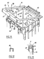
- FIG. 11 shows a container 40 according to a second embodiment of the invention.
- This container 40 differs from the previous container by the absence of holding members 17 and 18, replaced by a frame 41 pivotally mounted at one end on a handle 42 secured to the rear wall 43 of the container 40.
- the latter has a wall front, referenced 44, and two side panels 45, each consisting of two flaps hinged together 45 a , 45 b , and a tilting bottom not shown like the container 1 described above.
- the frame 41 is shaped to engage on top on each side panel 45 to maintain the flaps thereof in extension of one another.
- the side parts 46 of the frame 41 are shaped to engage the upper edges of the side panels 45 in deployed position and have, in cross section, as shown in Figure 13, a section having the general shape of a U open downwards.
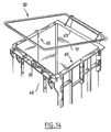
- the frame 41 is provided at the front with a flange 47 forming with the front wall 44, when it is folded over the side panels 45, a groove open downwards, allowing the introduction of a lifting member P a waste collection device.
- the front wall 44 has a rib 48 projecting outwards and intended to serve as a stop for this member P, shown in dotted lines in FIG. 14.
- a plate V of the latter comes close to or in contact with the top of the frame 41 to prevent it from pivoting and to keep the container in the unfolded state.
- the user lifts the frame 41 and makes it pivot backwards until it extends opposite the external face of the rear wall 43.
- FIG. 14 shows a container 50 according to a third embodiment of the invention.
- This container 50 differs from the container 40 previously described in that the frame 41 is replaced by a frame 51 articulated at one end on the rear panel 43 and capable of engaging at the other end with a clamp 52 secured to the wall. before 44.
- the frame 51 In the unfolded position of the container, the frame 51 is retained at the front by the clamp 52 and prevents the front 44 and rear 43 walls from coming together.
- the user lifts the front end of the frame 51 to disengage it from the clamp 52 and makes it pivot backwards until it comes opposite the external face of the rear wall 43 .
- the container 1 'differs from those previously described mainly by the fact that it does not include means for holding the container in the unfolded state other than the bottom wall.
- the container 1 ' has larger dimensions than those of the containers described above and rests on four steerable wheels 9' pivoting around vertical axes and fixed two by two respectively to the front walls 2 'and rear 3'.
- the raising of the bottom wall 13 ′ can be assisted in this embodiment of the invention by a spring or jack mechanism known in itself and not shown.
- the flaps 4 a ′ and 4 b ′ are articulated with one another by means of articulations constituted by hinges 5 ′ each comprising an axis engaged over the entire height of the parts to be assembled in pivoting, in overlapping passages of the latter.
- the hinges 5 ′ could be replaced by film hinges formed by molding with the front and rear walls.
- each side panel is produced with more than two flaps.
- the user raises the bottom wall and brings the front 2' and rear 3 'walls together.
- the flaps 4 a ′ and 4 b ′ then pivot towards the inside of the container 1 ′ until the latter is completely folded up, as shown in FIG. 16.
- the container 1 ′ can be provided in an alternative embodiment, not shown, with one or more holding members at its upper part, as described with reference to FIGS. 1 to 4.
- the bottom wall may be provided at its periphery with a sealing lip which is applied, when the container is in the deployed state, to the internal face of the front, rear and side panels.
- the holding members referenced 17, 18 and 41 make it possible to stiffen the upper part of the container in the deployed state and ensure good resistance during emptying.
Landscapes
- Engineering & Computer Science (AREA)
- Mechanical Engineering (AREA)
- Refuse Receptacles (AREA)
- Cartons (AREA)
Applications Claiming Priority (4)
| Application Number | Priority Date | Filing Date | Title |
|---|---|---|---|
| FR9506106 | 1995-05-23 | ||
| FR9506106A FR2734553B1 (fr) | 1995-05-23 | 1995-05-23 | Conteneur pour la collecte de dechets |
| FR9603413 | 1996-03-19 | ||
| FR9603413A FR2746379B1 (fr) | 1996-03-19 | 1996-03-19 | Conteneur pour la collecte de dechets |
Publications (2)
| Publication Number | Publication Date |
|---|---|
| EP0744360A1 true EP0744360A1 (de) | 1996-11-27 |
| EP0744360B1 EP0744360B1 (de) | 2000-05-03 |
Family
ID=26231981
Family Applications (1)
| Application Number | Title | Priority Date | Filing Date |
|---|---|---|---|
| EP96401121A Expired - Lifetime EP0744360B1 (de) | 1995-05-23 | 1996-05-23 | Müllsammelbehälter und Verfahren zu seiner Verwendung |
Country Status (6)
| Country | Link |
|---|---|
| US (1) | US6073943A (de) |
| EP (1) | EP0744360B1 (de) |
| JP (1) | JPH09150902A (de) |
| DE (2) | DE744360T1 (de) |
| DK (1) | DK0744360T3 (de) |
| ES (1) | ES2095822T3 (de) |
Cited By (2)
| Publication number | Priority date | Publication date | Assignee | Title |
|---|---|---|---|---|
| FR2943327A1 (fr) * | 2009-03-23 | 2010-09-24 | Geprom | Conteneur notamment pour collecter des dechets hospitaliers contamines |
| WO2015028160A1 (en) * | 2013-08-30 | 2015-03-05 | Howdens Joinery Plc | Furniture article |
Families Citing this family (50)
| Publication number | Priority date | Publication date | Assignee | Title |
|---|---|---|---|---|
| AU739538B2 (en) * | 1997-08-04 | 2001-10-18 | Waste Management Pacific Pty Ltd | Bin with hinged wings |
| US6431580B1 (en) * | 1999-02-25 | 2002-08-13 | Darren J. Kady | Accessories for a collapsible rolling caddy |
| US6267393B1 (en) * | 1999-08-06 | 2001-07-31 | Frank Mengrone | Wheeled personal item caddy |
| US6443481B1 (en) * | 2000-06-21 | 2002-09-03 | David M. Stravitz | Collapsible movable cart |
| WO2002092412A2 (en) * | 2001-05-17 | 2002-11-21 | Kady Darren J | Accessories for a collapsible rolling caddy |
| US6955365B2 (en) * | 2002-02-26 | 2005-10-18 | Paul Giampavolo | Collapsible wheeled shopping container |
| GB2398776B (en) * | 2003-01-14 | 2005-07-20 | Stephen Capon | Collapsible wheelybin |
| US7731221B2 (en) * | 2006-09-21 | 2010-06-08 | Bess Suzan L | Collapsible and portable wheeled dolly particularly suitable for use by students or others in the transport of items |
| US7748798B2 (en) * | 2006-10-25 | 2010-07-06 | Kohler Co. | Collapsible furniture and braces useful therewith |
| WO2008062286A2 (es) * | 2006-11-23 | 2008-05-29 | Ricardo Ceballos-Godefroy | Carro de servicio colapsable |
| US20100225078A1 (en) * | 2006-12-01 | 2010-09-09 | Washington Savannah River Company Llc | Container for Soiled Clothing |
| US8123061B1 (en) | 2007-03-26 | 2012-02-28 | Charles Kenneth Brown | Refuse container |
| US20080238011A1 (en) * | 2007-03-29 | 2008-10-02 | Howard Hammel | Mobile article transporter |
| US20090020971A1 (en) * | 2007-07-18 | 2009-01-22 | Edgard Makdisse | Shopping Cart |
| WO2009075781A1 (en) * | 2007-12-05 | 2009-06-18 | Tadeo Maria I | Collapsible rolling tote bag |
| US7726671B2 (en) * | 2008-03-04 | 2010-06-01 | Skyworld Business Group, Inc. | Wheeled shopping bag |
| US20090283990A1 (en) * | 2008-05-15 | 2009-11-19 | Sandra Louise Graham | EZ BN green shopping bag with wheels |
| US7980455B2 (en) * | 2009-03-12 | 2011-07-19 | Gloria Ivette Leiva Burgos | Foldable urban waste container |
| US8172239B1 (en) * | 2009-07-01 | 2012-05-08 | Cherylene Boyd | Collapsible shopping cart system |
| USD625895S1 (en) * | 2009-08-20 | 2010-10-19 | Juan Carlos Musi | Collapsible bag with wheeled cart |
| US20110192841A1 (en) * | 2010-02-05 | 2011-08-11 | Standfield Laranard Hunter | Folding trash can |
| US8342461B2 (en) * | 2010-03-03 | 2013-01-01 | Butler Concepts, Llc | Collapsible waste and recycling bag holder |
| US8439374B1 (en) * | 2010-05-14 | 2013-05-14 | Richard Elden | Lightweight high load capacity folding utility cart with unique support structure and ergonomic handle |
| US8840072B2 (en) | 2010-06-22 | 2014-09-23 | Pratt Industries, Inc. | Bag stand |
| CN102649501A (zh) * | 2011-02-23 | 2012-08-29 | 吴江金达精工机械有限公司 | 一种可折叠垃圾桶 |
| US9056715B2 (en) * | 2011-07-18 | 2015-06-16 | Pratt Industries, Inc. | Bag stand |
| US8820777B1 (en) * | 2013-07-10 | 2014-09-02 | Richard Pargansky | Collapsible valet cart |
| GB201312371D0 (en) * | 2013-07-10 | 2013-08-21 | Carpenter Caroline G | Refuse containers |
| US10246115B2 (en) * | 2013-09-18 | 2019-04-02 | Allpillars, Inc. | Food, water and vital supplies storage and transport cart |
| US9550602B2 (en) * | 2013-09-18 | 2017-01-24 | Allpillars, Inc. | Collapsible reusable carrying cases |
| FR3016778A1 (fr) * | 2014-01-27 | 2015-07-31 | Delsey Soc | Bagage a variation de volume |
| US20150225004A1 (en) * | 2014-02-10 | 2015-08-13 | Bryan P. Dunford | Collapsible Rolling Cart |
| US9915582B2 (en) * | 2014-10-03 | 2018-03-13 | Offshore Energy Services, Inc. | Modular pressure testing unit |
| CN204218313U (zh) * | 2014-10-24 | 2015-03-25 | 蒂尚贸易(上海)有限公司 | 一种可折叠的布菲车 |
| US10246254B2 (en) | 2016-03-23 | 2019-04-02 | Ex-Cell Kaiser LLC | Collapsible waste receptacle |
| USD803504S1 (en) | 2016-06-16 | 2017-11-21 | Ex-Cell Kaiser LLC | Waste receptacle |
| GB2561346B (en) * | 2017-04-06 | 2021-03-17 | Addis Housewares Ltd | A reconfigurable container |
| CN109131124A (zh) * | 2018-10-09 | 2019-01-04 | 四川天非尼迪新能源科技有限公司 | 一种折叠式低速电动汽车后背篓装置 |
| US12297040B2 (en) | 2019-09-06 | 2025-05-13 | Pratt Corrugated Holdings, Inc. | Lawn refuse bag |
| USD929238S1 (en) | 2019-12-04 | 2021-08-31 | Pratt Corrugated Holdings, Inc. | Lawn refuse bag |
| USD935124S1 (en) | 2019-12-04 | 2021-11-02 | Pratt Corrugated Holdings, Inc. | Lawn refuse bag insert |
| BE1028568B1 (nl) * | 2020-08-28 | 2022-03-29 | Maenhout | Multifuncionele elektrische kar en aanverwanten |
| KR102195712B1 (ko) * | 2020-08-31 | 2020-12-28 | 후소특장차주식회사 | 폐기물 수거차량용 수거함 |
| WO2022048991A1 (en) * | 2020-09-01 | 2022-03-10 | John Dunne | A refuse receptacle |
| US20220161994A1 (en) * | 2020-11-25 | 2022-05-26 | Isaac Blake, III | Outdoor Garbage Container |
| US12172705B2 (en) | 2021-06-03 | 2024-12-24 | Abc Technologies Inc. | Split tailgate storage and accessory system |
| US11459046B1 (en) * | 2021-07-15 | 2022-10-04 | GM Global Technology Operations LLC | Service table for transporting a battery pack of a motor vehicle along a floor surface |
| US20250326418A1 (en) * | 2022-12-16 | 2025-10-23 | Enwei ZHANG | Outdoor camping apparatus, camping cart, and foldable frame |
| US12292229B2 (en) * | 2023-01-24 | 2025-05-06 | Epazz, Inc | Foldable refrigerator |
| CN223860331U (zh) * | 2025-01-04 | 2026-02-03 | 石忠磊 | 可折叠箱体和应用可折叠箱体的购物车 |
Citations (10)
| Publication number | Priority date | Publication date | Assignee | Title |
|---|---|---|---|---|
| US2371472A (en) * | 1942-06-26 | 1945-03-13 | Ruff Arthur George | Cart |
| US2564939A (en) * | 1947-09-29 | 1951-08-21 | Louis S Weast | Foldable shopping cart |
| FR1017360A (fr) * | 1950-05-09 | 1952-12-09 | Perfectionnements aux boîtes et récipients pliants | |
| US2891803A (en) * | 1957-03-27 | 1959-06-23 | Mintz Julius | Collapsible shopping cart |
| US3135527A (en) * | 1961-07-28 | 1964-06-02 | Philip B Knapp | Wheeled market carts |
| FR2473997A1 (fr) * | 1980-01-18 | 1981-07-24 | Streuber Sulo Eisenwerk F | Poubelle de grande capacite en matiere plastique |
| FR2579158A1 (fr) * | 1985-03-22 | 1986-09-26 | Boufedji Farid | Chariot a provisions pliable et retractable utilisable en grandes surfaces et pour les marches |
| DE3703034C1 (de) * | 1987-02-02 | 1988-04-14 | Otto Geb Kg | Muellbehaelter mit einer nach unten offenen Aufnahmetasche zum Eingriff eines Greifers |
| US4953878A (en) * | 1988-10-31 | 1990-09-04 | Sbragia Frank J | Collapsible cart |
| FR2663307A1 (fr) * | 1990-06-14 | 1991-12-20 | Verbiese Raphael | Conteneur de dechets alimentaires collectifs. |
Family Cites Families (12)
| Publication number | Priority date | Publication date | Assignee | Title |
|---|---|---|---|---|
| US2472203A (en) * | 1947-07-18 | 1949-06-07 | Friedmann Siegfried | Collapsible parcel carrier |
| US2668977A (en) * | 1949-07-16 | 1954-02-16 | H F Woodward | Wheeled vacuum cleaner cart |
| US2716558A (en) * | 1953-12-28 | 1955-08-30 | Anna K Sullivan | Article carrying and rolling-transport device |
| US2832606A (en) * | 1954-12-31 | 1958-04-29 | David D Patterson | Portable parcel carriers |
| US3376986A (en) * | 1966-05-12 | 1968-04-09 | Farber Henry | Detachable garbage can carrier |
| CA1244214A (en) * | 1985-05-30 | 1988-11-08 | Ed J. Molodecki | Collapsible hut structure |
| US4746059A (en) * | 1987-04-01 | 1988-05-24 | General Foods Inc. | Collapsible container and a method for loading a product into and unloading the product from a collapsible container |
| US4753367A (en) * | 1987-10-19 | 1988-06-28 | Mobil Oil Corporation | Wastebasket and inner liner retainer |
| US5460391A (en) * | 1993-08-27 | 1995-10-24 | Leonard Bloom | Combination tray and wheeled cart |
| US5363980A (en) * | 1993-09-22 | 1994-11-15 | Mulcahy Stephen J | Combination disposable waste container |
| US5464237A (en) * | 1994-06-28 | 1995-11-07 | Saporiti; Elena H. | Folding cart |
| US5730451A (en) * | 1996-03-11 | 1998-03-24 | Walker; Lawrence | Miracle top garbage cart |
-
1996
- 1996-05-23 DE DE0744360T patent/DE744360T1/de active Pending
- 1996-05-23 EP EP96401121A patent/EP0744360B1/de not_active Expired - Lifetime
- 1996-05-23 DK DK96401121T patent/DK0744360T3/da active
- 1996-05-23 DE DE69608025T patent/DE69608025T2/de not_active Expired - Lifetime
- 1996-05-23 US US08/652,795 patent/US6073943A/en not_active Expired - Lifetime
- 1996-05-23 JP JP8166584A patent/JPH09150902A/ja active Pending
- 1996-05-23 ES ES96401121T patent/ES2095822T3/es not_active Expired - Lifetime
Patent Citations (10)
| Publication number | Priority date | Publication date | Assignee | Title |
|---|---|---|---|---|
| US2371472A (en) * | 1942-06-26 | 1945-03-13 | Ruff Arthur George | Cart |
| US2564939A (en) * | 1947-09-29 | 1951-08-21 | Louis S Weast | Foldable shopping cart |
| FR1017360A (fr) * | 1950-05-09 | 1952-12-09 | Perfectionnements aux boîtes et récipients pliants | |
| US2891803A (en) * | 1957-03-27 | 1959-06-23 | Mintz Julius | Collapsible shopping cart |
| US3135527A (en) * | 1961-07-28 | 1964-06-02 | Philip B Knapp | Wheeled market carts |
| FR2473997A1 (fr) * | 1980-01-18 | 1981-07-24 | Streuber Sulo Eisenwerk F | Poubelle de grande capacite en matiere plastique |
| FR2579158A1 (fr) * | 1985-03-22 | 1986-09-26 | Boufedji Farid | Chariot a provisions pliable et retractable utilisable en grandes surfaces et pour les marches |
| DE3703034C1 (de) * | 1987-02-02 | 1988-04-14 | Otto Geb Kg | Muellbehaelter mit einer nach unten offenen Aufnahmetasche zum Eingriff eines Greifers |
| US4953878A (en) * | 1988-10-31 | 1990-09-04 | Sbragia Frank J | Collapsible cart |
| FR2663307A1 (fr) * | 1990-06-14 | 1991-12-20 | Verbiese Raphael | Conteneur de dechets alimentaires collectifs. |
Cited By (2)
| Publication number | Priority date | Publication date | Assignee | Title |
|---|---|---|---|---|
| FR2943327A1 (fr) * | 2009-03-23 | 2010-09-24 | Geprom | Conteneur notamment pour collecter des dechets hospitaliers contamines |
| WO2015028160A1 (en) * | 2013-08-30 | 2015-03-05 | Howdens Joinery Plc | Furniture article |
Also Published As
| Publication number | Publication date |
|---|---|
| US6073943A (en) | 2000-06-13 |
| ES2095822T3 (es) | 2000-07-16 |
| DE69608025D1 (de) | 2000-06-08 |
| EP0744360B1 (de) | 2000-05-03 |
| JPH09150902A (ja) | 1997-06-10 |
| DE69608025T2 (de) | 2001-01-11 |
| ES2095822T1 (es) | 1997-03-01 |
| DK0744360T3 (da) | 2000-10-23 |
| DE744360T1 (de) | 1997-07-10 |
Similar Documents
| Publication | Publication Date | Title |
|---|---|---|
| EP0744360B1 (de) | Müllsammelbehälter und Verfahren zu seiner Verwendung | |
| EP1369276A1 (de) | Hintere Haube für Kraftfahrzeug | |
| EP3016821B1 (de) | Kofferraumabdeckungssystem für kraftfahrzeug | |
| FR2851509A1 (fr) | Dispositif de toit escamotable et vehicule equipe d'un tel dispositif | |
| CH632217A5 (fr) | Dispositif de tassement de charges solides dans un receptacle. | |
| EP1470012A2 (de) | Kofferraumdeckel für ein cabriofahrzeug mit faltverdeck | |
| FR2865684A1 (fr) | Toit escamotable dans le coffre arriere d'un vehicule, comprenant des elements lateraux deplacables | |
| EP0634344B1 (de) | Doppelkammer-Behälter zum Sammeln von Abfällen, insbesondere Hausmüll | |
| EP0285467B1 (de) | Müllsammelbehälter | |
| FR2746379A1 (fr) | Conteneur pour la collecte de dechets | |
| EP0373989B1 (de) | Behälterverschlusskappe mit schwenkbarem Betätigungselement zum Abgeben des Behälterinhalts | |
| FR2847863A1 (fr) | Vehicule automobile transformable en vehicule a benne ouverte vers le haut. | |
| EP1098827A1 (de) | Sammel- und transportbehälter für haushaltsmüll | |
| FR2851510A1 (fr) | Dispositif de toit escamotable et vehicule equipe d'un tel dispositif | |
| FR2795443A1 (fr) | Cles, notamment de vehicule automobile, comportant une partie formant panneton et une partie de prehension | |
| EP1198362B1 (de) | Versenkbares dachsystem | |
| FR2896207A1 (fr) | Vide poche escamotable pour planche de bord de vehicule automobile. | |
| FR2746059A1 (fr) | Porte laterale de vehicule automobile a cinematique d'ouverture perfectionnee | |
| FR2734553A1 (fr) | Conteneur pour la collecte de dechets | |
| FR2679844A1 (fr) | Coffre a volume variable. | |
| EP4271620B1 (de) | Faltverpackung mit sicherer flacher konfiguration | |
| FR2713881A1 (fr) | Bac de récupération et de stockage pour tondeuse à gazon ou matériel similaire. | |
| FR3163355A1 (fr) | Mécanisme de déclipsage par rotation d’un ouvrant contre un dormant | |
| EP1721835A2 (de) | Verschlusskappe und damit versehener Behälter. | |
| EP4281382A1 (de) | Zusammenlegbarer behälter insbesondere zum transport von obst und gemüse |
Legal Events
| Date | Code | Title | Description |
|---|---|---|---|
| PUAI | Public reference made under article 153(3) epc to a published international application that has entered the european phase |
Free format text: ORIGINAL CODE: 0009012 |
|
| AK | Designated contracting states |
Kind code of ref document: A1 Designated state(s): BE CH DE DK ES FR GB IT LI SE |
|
| ITCL | It: translation for ep claims filed |
Representative=s name: MODIANO & ASSOCIATI S.R.L. |
|
| REG | Reference to a national code |
Ref country code: ES Ref legal event code: BA2A Ref document number: 2095822 Country of ref document: ES Kind code of ref document: T1 |
|
| 17P | Request for examination filed |
Effective date: 19961228 |
|
| GBC | Gb: translation of claims filed (gb section 78(7)/1977) | ||
| DET | De: translation of patent claims | ||
| 17Q | First examination report despatched |
Effective date: 19970708 |
|
| GRAG | Despatch of communication of intention to grant |
Free format text: ORIGINAL CODE: EPIDOS AGRA |
|
| GRAG | Despatch of communication of intention to grant |
Free format text: ORIGINAL CODE: EPIDOS AGRA |
|
| GRAH | Despatch of communication of intention to grant a patent |
Free format text: ORIGINAL CODE: EPIDOS IGRA |
|
| GRAH | Despatch of communication of intention to grant a patent |
Free format text: ORIGINAL CODE: EPIDOS IGRA |
|
| GRAA | (expected) grant |
Free format text: ORIGINAL CODE: 0009210 |
|
| AK | Designated contracting states |
Kind code of ref document: B1 Designated state(s): BE CH DE DK ES FR GB IT LI SE |
|
| REG | Reference to a national code |
Ref country code: CH Ref legal event code: EP |
|
| REF | Corresponds to: |
Ref document number: 69608025 Country of ref document: DE Date of ref document: 20000608 |
|
| REG | Reference to a national code |
Ref country code: CH Ref legal event code: NV Representative=s name: KIRKER & CIE SA |
|
| REG | Reference to a national code |
Ref country code: ES Ref legal event code: FG2A Ref document number: 2095822 Country of ref document: ES Kind code of ref document: T3 |
|
| ITF | It: translation for a ep patent filed | ||
| GBT | Gb: translation of ep patent filed (gb section 77(6)(a)/1977) |
Effective date: 20000706 |
|
| REG | Reference to a national code |
Ref country code: DK Ref legal event code: T3 |
|
| PLBE | No opposition filed within time limit |
Free format text: ORIGINAL CODE: 0009261 |
|
| STAA | Information on the status of an ep patent application or granted ep patent |
Free format text: STATUS: NO OPPOSITION FILED WITHIN TIME LIMIT |
|
| 26N | No opposition filed | ||
| REG | Reference to a national code |
Ref country code: GB Ref legal event code: IF02 |
|
| PGFP | Annual fee paid to national office [announced via postgrant information from national office to epo] |
Ref country code: SE Payment date: 20050516 Year of fee payment: 10 |
|
| PGFP | Annual fee paid to national office [announced via postgrant information from national office to epo] |
Ref country code: DK Payment date: 20050520 Year of fee payment: 10 |
|
| PGFP | Annual fee paid to national office [announced via postgrant information from national office to epo] |
Ref country code: BE Payment date: 20050609 Year of fee payment: 10 |
|
| PGFP | Annual fee paid to national office [announced via postgrant information from national office to epo] |
Ref country code: CH Payment date: 20050808 Year of fee payment: 10 |
|
| PG25 | Lapsed in a contracting state [announced via postgrant information from national office to epo] |
Ref country code: SE Free format text: LAPSE BECAUSE OF NON-PAYMENT OF DUE FEES Effective date: 20060524 |
|
| PG25 | Lapsed in a contracting state [announced via postgrant information from national office to epo] |
Ref country code: LI Free format text: LAPSE BECAUSE OF NON-PAYMENT OF DUE FEES Effective date: 20060531 Ref country code: DK Free format text: LAPSE BECAUSE OF NON-PAYMENT OF DUE FEES Effective date: 20060531 Ref country code: CH Free format text: LAPSE BECAUSE OF NON-PAYMENT OF DUE FEES Effective date: 20060531 Ref country code: BE Free format text: LAPSE BECAUSE OF NON-PAYMENT OF DUE FEES Effective date: 20060531 |
|
| REG | Reference to a national code |
Ref country code: CH Ref legal event code: PL Ref country code: DK Ref legal event code: EBP |
|
| EUG | Se: european patent has lapsed | ||
| BERE | Be: lapsed |
Owner name: CIE PLASTIC *OMNIUM Effective date: 20060531 |
|
| PGFP | Annual fee paid to national office [announced via postgrant information from national office to epo] |
Ref country code: IT Payment date: 20110531 Year of fee payment: 16 |
|
| PG25 | Lapsed in a contracting state [announced via postgrant information from national office to epo] |
Ref country code: IT Free format text: LAPSE BECAUSE OF NON-PAYMENT OF DUE FEES Effective date: 20120523 |
|
| REG | Reference to a national code |
Ref country code: FR Ref legal event code: PLFP Year of fee payment: 20 |
|
| PGFP | Annual fee paid to national office [announced via postgrant information from national office to epo] |
Ref country code: ES Payment date: 20150626 Year of fee payment: 20 Ref country code: GB Payment date: 20150529 Year of fee payment: 20 Ref country code: DE Payment date: 20150529 Year of fee payment: 20 |
|
| PGFP | Annual fee paid to national office [announced via postgrant information from national office to epo] |
Ref country code: FR Payment date: 20150528 Year of fee payment: 20 |
|
| REG | Reference to a national code |
Ref country code: DE Ref legal event code: R071 Ref document number: 69608025 Country of ref document: DE |
|
| REG | Reference to a national code |
Ref country code: GB Ref legal event code: PE20 Expiry date: 20160522 |
|
| PG25 | Lapsed in a contracting state [announced via postgrant information from national office to epo] |
Ref country code: GB Free format text: LAPSE BECAUSE OF EXPIRATION OF PROTECTION Effective date: 20160522 |
|
| REG | Reference to a national code |
Ref country code: ES Ref legal event code: FD2A Effective date: 20160830 |
|
| PG25 | Lapsed in a contracting state [announced via postgrant information from national office to epo] |
Ref country code: ES Free format text: LAPSE BECAUSE OF EXPIRATION OF PROTECTION Effective date: 20160524 |