EP1369276A1 - Hintere Haube für Kraftfahrzeug - Google Patents
Hintere Haube für Kraftfahrzeug Download PDFInfo
- Publication number
- EP1369276A1 EP1369276A1 EP03291312A EP03291312A EP1369276A1 EP 1369276 A1 EP1369276 A1 EP 1369276A1 EP 03291312 A EP03291312 A EP 03291312A EP 03291312 A EP03291312 A EP 03291312A EP 1369276 A1 EP1369276 A1 EP 1369276A1
- Authority
- EP
- European Patent Office
- Prior art keywords
- roof
- window
- vehicle
- flap
- panel
- Prior art date
- Legal status (The legal status is an assumption and is not a legal conclusion. Google has not performed a legal analysis and makes no representation as to the accuracy of the status listed.)
- Withdrawn
Links
Images


Classifications
-
- B—PERFORMING OPERATIONS; TRANSPORTING
- B60—VEHICLES IN GENERAL
- B60J—WINDOWS, WINDSCREENS, NON-FIXED ROOFS, DOORS, OR SIMILAR DEVICES FOR VEHICLES; REMOVABLE EXTERNAL PROTECTIVE COVERINGS SPECIALLY ADAPTED FOR VEHICLES
- B60J5/00—Doors
- B60J5/10—Doors arranged at the vehicle rear
- B60J5/101—Doors arranged at the vehicle rear for non-load transporting vehicles, i.e. family cars including vans
- B60J5/102—Doors arranged at the vehicle rear for non-load transporting vehicles, i.e. family cars including vans comprising door or part of door being pivotable downwards about horizontal axis to open position
- B60J5/103—Doors arranged at the vehicle rear for non-load transporting vehicles, i.e. family cars including vans comprising door or part of door being pivotable downwards about horizontal axis to open position where lower door part moves independently from other door structures, e.g. by being hinged on the vehicle body
-
- B—PERFORMING OPERATIONS; TRANSPORTING
- B60—VEHICLES IN GENERAL
- B60J—WINDOWS, WINDSCREENS, NON-FIXED ROOFS, DOORS, OR SIMILAR DEVICES FOR VEHICLES; REMOVABLE EXTERNAL PROTECTIVE COVERINGS SPECIALLY ADAPTED FOR VEHICLES
- B60J1/00—Windows; Windscreens; Accessories therefor
- B60J1/18—Windows; Windscreens; Accessories therefor arranged at the vehicle rear
- B60J1/1838—Windows; Windscreens; Accessories therefor arranged at the vehicle rear movable for non-convertible vehicles, including vehicles with versatile load area
- B60J1/1846—Windows; Windscreens; Accessories therefor arranged at the vehicle rear movable for non-convertible vehicles, including vehicles with versatile load area where the window can slide
- B60J1/1869—Windows; Windscreens; Accessories therefor arranged at the vehicle rear movable for non-convertible vehicles, including vehicles with versatile load area where the window can slide to an end position parallel to roof
-
- B—PERFORMING OPERATIONS; TRANSPORTING
- B60—VEHICLES IN GENERAL
- B60J—WINDOWS, WINDSCREENS, NON-FIXED ROOFS, DOORS, OR SIMILAR DEVICES FOR VEHICLES; REMOVABLE EXTERNAL PROTECTIVE COVERINGS SPECIALLY ADAPTED FOR VEHICLES
- B60J1/00—Windows; Windscreens; Accessories therefor
- B60J1/18—Windows; Windscreens; Accessories therefor arranged at the vehicle rear
- B60J1/1838—Windows; Windscreens; Accessories therefor arranged at the vehicle rear movable for non-convertible vehicles, including vehicles with versatile load area
- B60J1/1876—Windows; Windscreens; Accessories therefor arranged at the vehicle rear movable for non-convertible vehicles, including vehicles with versatile load area where the window is pivotable relative to a stationary axis
- B60J1/1884—Windows; Windscreens; Accessories therefor arranged at the vehicle rear movable for non-convertible vehicles, including vehicles with versatile load area where the window is pivotable relative to a stationary axis about a horizontal axis
-
- B—PERFORMING OPERATIONS; TRANSPORTING
- B60—VEHICLES IN GENERAL
- B60J—WINDOWS, WINDSCREENS, NON-FIXED ROOFS, DOORS, OR SIMILAR DEVICES FOR VEHICLES; REMOVABLE EXTERNAL PROTECTIVE COVERINGS SPECIALLY ADAPTED FOR VEHICLES
- B60J10/00—Sealing arrangements
- B60J10/80—Sealing arrangements specially adapted for opening panels, e.g. doors
-
- B—PERFORMING OPERATIONS; TRANSPORTING
- B60—VEHICLES IN GENERAL
- B60J—WINDOWS, WINDSCREENS, NON-FIXED ROOFS, DOORS, OR SIMILAR DEVICES FOR VEHICLES; REMOVABLE EXTERNAL PROTECTIVE COVERINGS SPECIALLY ADAPTED FOR VEHICLES
- B60J5/00—Doors
- B60J5/10—Doors arranged at the vehicle rear
- B60J5/101—Doors arranged at the vehicle rear for non-load transporting vehicles, i.e. family cars including vans
- B60J5/107—Doors arranged at the vehicle rear for non-load transporting vehicles, i.e. family cars including vans constructional details, e.g. about door frame, panels, materials used, reinforcements
Definitions
- the present invention relates to a device forming a rear trunk flap of a motor vehicle.
- tailgate as a component for closing the rear trunk of a motor vehicle.
- the object of the present invention is to eliminate the above disadvantage by proposing a device forming rear boot lid of a motor vehicle allowing the depositing of objects in the rear boot without be forced to fully open the rear door.
- the boot flap device rear of a motor vehicle fitted with a window rear which can be arranged above the rear flap substantially as an extension of this component occupying its rear boot closing position, is characterized in that the rear window is pivotally mounted at the rear part of the roof of the vehicle along an axis transverse to the latter opposite the flap and can pivot between its closed rear trunk position as an extension of the closed flap and a position opening approximately in extension of the pavilion freeing up the space above the closed shutter to access the trunk.
- the rear window can slide from guided in translation along the pavilion above from it towards the front of the vehicle from its open position to a stowed position retracted not protruding from the rear of the vehicle.
- the rear window is mounted pivoting to the roof via two hinges on each side of the glass and whose axes of articulation are coaxial transversely to the vehicle, the movable element of each hinge being fixed to the glass in the vicinity of its edge opposite the rear flap while the fixed element of the hinge is fitted with a rolling roller housed in a longitudinal side guide rail of the roof for allow bilaterally guided sliding of the rear window along the guide rails.
- the rear window can be blocked relative to the guide rails in its most advanced retracted position on the rails by means of automatic locking.
- the pavilion is equipped with a rear roof panel opening with displacement controlled in translation and bilaterally guided relative to the pavilion between a closed roof position and an advanced position on the opening pavilion of the rear part of the pavilion and the rear window guide rails are fixed each side of the rear roof sun panel under this to allow the rear window to slide relative to the panel above it from the window open position when the panel occupies its closed position of the pavilion until the rear window is locked relative to the panel at its advanced position above it by the automatic locking means.
- the sunroof panel can drive kinematically the rear window towards the front of the vehicle in the locked position of the window relative to the panel when the latter is moved to its position advanced opening of the rear part of the roof for partially configure the vehicle in pick-up.
- the rear sunroof panel is mounted bilaterally guided on a frame with side rails of integral guidance of the pavilion.
- each articulation hinge of the rear window is in the form of a yoke located above of the rear sunroof panel which has a lateral tab external to the panel at the end lower of which the rotation roller is mounted bearing housed in its guide rail below the sunroof panel.
- the rear window can be locked at its closed position to the rear shutter closed by a unlockable locking mechanism comprising a locking finger secured to the window when crossing this and a locking box fixed in the shutter rear and in which can engage the finger of locking to be blocked by a slide movement controlled in the housing by a motor electric housed in the rear flap.
- a unlockable locking mechanism comprising a locking finger secured to the window when crossing this and a locking box fixed in the shutter rear and in which can engage the finger of locking to be blocked by a slide movement controlled in the housing by a motor electric housed in the rear flap.
- the locking finger is integral with its opposite end of an external operating handle located near the lower edge of the rear window substantially in the middle of it.
- the rear flap is hinged on its edge lower than the vehicle body by two hinges spaced whose axes of articulation are coaxial and transverse to the longitudinal axis of the vehicle to allow the shutter to swing to its open position approximately as an extension of the vehicle floor when the rear window is at least in its position opening.
- Back cover can be locked in position closing the vehicle body by a mechanism unlockable lock with two locking fingers interlocking secured respectively to the two uprights of the vehicle body delimiting the opening of the trunk rear protruding from these uprights and two locking boxes fixed in the rear flap of each side of it at its top opposite to the articulation of the flap and in each of which can engage a locking finger to be blocked by a displacement slide controlled in the housing by an electric motor housed in the rear housing.
- Two lateral gas cylinders are mounted articulated between the vehicle body and the rear window at its ends opposite its articulation to the roof for allow controlled pivoting of the glass to its open position in extension of the roof.
- the sunroof rear panel is movable along the pavilion by an electric motor controlled by distance and connected to the panel by means drive.
- rear roof panel type motor vehicle opening which can slide in translation of the part rear of the vehicle roof towards the front of it and rear trunk closing flap that can pivot from its closed position to its open position in rear trunk floor extension but it is of course it can apply to any other type vehicle such as for example a roof vehicle with no movable sunroof panel.
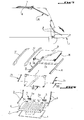
- the motor vehicle is fitted with a flap 1 for closing the rear boot of the vehicle and pivotally mounted by its lower edge to the vehicle body following a transverse joint allowing it to switch from its closed position to trunk in its open position at which shutter 1 is located approximately in the extension of the floor 2 of the rear boot of the vehicle.
- the shutter 1 is formed by an outer panel in sheet 3 and a lining 4 secured to the outer panel 3 while being turned towards the interior of the trunk in shutter closed position 1.
- the articulation of the part 1 to the body C of the vehicle consists of two articulation hinges 5 arranged symmetrically at the longitudinal median plane of the vehicle, the movable element 5a of each hinge 5 being fixed, for example by welding or by screwing, to an end wall of the lining 4 of the shutter 1 while the fixed element 5b of the hinge 5 is fixed, for example by welding or screwing, to the body C of the vehicle substantially at floor 2 of the rear trunk, the two hinges 5c between the two movable and fixed elements 5a and 5b of the hinges 5 being coaxial and extending transversely to vehicle.
- a 5d transverse joint is fixed to the body at the level of the rear transverse edge of the rear boot for seal between the lower part of the shutter 1 and the trunk.
- the rear flap 1 is retained in its position opening by two lateral pairs of articulated arms 6 like a compass, one of the arms of each pair being fixed by its end in an articulated manner to the amount M of body C of the delimiting vehicle the rear opening of the trunk while the other arm of this pair is fixed by its opposite end to the wall corresponding side of the lining 4 substantially at middle of it.
- the rear flap 1 can be locked in position closed at the vehicle body by a mechanism controlled locking which will be described later.
- the rear flap 1 In its closed position, the rear flap 1 is surmounted by a window 7 enabling closure complete with the rear trunk of the vehicle.
- the sunroof panel 8 which can be produced made of a translucent material, plastic or sheet metal, is slidably mounted in a controlled manner translation on a frame 9 with side rails 10 and cross member 11 connecting the side members and integral with the vehicle roof so as to move the panel 8 in before or behind the next vehicle you want open or close the rear roof section overlooking the rear trunk of the vehicle.
- Two longitudinal roof bars 12 integral with each side of the vehicle roof can be provided.
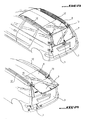
- the shutter window 7 is mounted swivel at the rear of the vehicle roof along an axis transverse to the opposite vehicle of the rear flap 1 and allowing the window 7 to pivot from its closed position, flap 1 closed, to a opening position approximately as an extension of flag and, more precisely in extension of the panel sunroof 8 when present, so to free up the space above the closed shutter 1 normally occupied by the window 7 in order to access the rear boot and deposit objects there without having to open the shutter 1, as shown in Figures 2 and 24.
- the shutter glass 7 can slide from guided way in translation towards the front of the vehicle the along the pavilion above it from its open position to a stowed position retracted, that is to say no longer protruding from the rear of the vehicle, above the rear pavilion or sun roof panel correspondent 8 when present, as shown in Figures 3 and 25.
- the shutter glass 7 is pivotally mounted at vehicle roof, particularly at the roof panel opening 8, via two hinges hinge 13 spaced on each side of the window 7 and whose articulation axes 14 are coaxial transversely to the vehicle.
- the moving element or pivoting 15 of each articulation hinge 13 is fixed to the window 7 in the vicinity of its transverse edge opposite the flap 1 while the fixed element 16 of the hinge 13, relative to which the element can pivot mobile 15, is mounted on the sunroof panel 8 and equipped with a roller 17 housed and retained in a lateral longitudinal guide rail 18 fixed below the corresponding side of the sunroof panel 8 to allow bilaterally guided sliding of the window 7 along the guide rails 18.
- each element 16 of articulation hinge 13 is in form of yoke above the lateral side corresponding to the sunroof panel 8, the yoke 16 comprising a lateral tab 19 external to the panel 8 the lower end of which extends below this panel rotates about a transverse axis 20 integral with the lug 19 the roller 17.
- guide rail 18 of each roller 17 has a lower part opposite panel 8 with section substantially U-shaped cross section in which can move the roller 17 and the side wall of this rail connected to the U-shaped lower part and opposite leg 19, ends at the top by a wall substantially at a right angle for fixing the rail 18 under panel 8 via bolts fixing 21.
- a protective seal 22 is interposed between the upper face of the sunroof panel 8 in sliding contact with it and element 16 of each hinge 13 by being integral with this element 16.
- Each mobile element 15 of a hinge hinge 13 is fixed to the window 7 by at least one fixing stud 23.
- two lateral cylinders 25, preferably of the gas type are provided, the cylinder 26 of each cylinder 25 being hingedly attached at its end to the vehicle body while the piston rod 27 of this cylinder is hinged at its end opposite the window 7 by means of a piece of support 28 fixed behind the window 7 in the vicinity of its corresponding corner opposite the hinge 13 by a bolt 29, a seal 30 being secured to the body C of the vehicle in the vicinity of the amount corresponding to the framing of the opening of the rear trunk to seal the glass 7 to its closed position along its lateral side corresponding.
- a protective stop 28a is fixed to the support piece 28 and is supported on the panel 8 when the window 7 is in position on the panel 8.
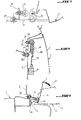
- the window 7 can be locked in its position of closing, to the rear flap closed 1 by a mechanism unlockable lock, preferably remotely, especially by the driver.
- this locking includes a locking finger 31 secured to the window 7 by means of a nut 32 and a threaded rod 33 passing perpendicularly the window 7 in the vicinity of its lower edge and at middle of it.
- An external operating handle 34 is fixed by screwing on the threaded rod 33 while being locked in abutment on the corresponding external face of the window 7.
- the locking mechanism further comprises a housing 35 fixed in the rear flap in part top of it between the outer panel 1 and the lining 4 and a slide element 36 is mounted mobile in rectilinear translation in the housing 35 in a finger 31 unlocking direction under the control an electric motor 37 fixed in shutter 1 on a reinforcement portion 38 secured to the internal face of the lining 4, the electric motor 37 being connected to the slide 36 by a metal rod 39.
- the motor electric 37 can be remotely controlled by a device actuation, such as a push button, located at the vehicle dashboard.
- the locking finger 31 crosses a hole made in the upper part of the external panel 3 of shutter 1 and engages transversely in the housing 35 to be blocked therein, in window 7 closed position, by the end conformed to this effect of the slide 36.
- the rod 39 moves in translation the slide 36 relative to the housing 35 in a direction disengaging the opposite end of the slide 36 of finger 31 to release the latter and allow a user to manually rotate the window 7 to its open position by pulling on the operating handle 24.
- An elastic member such as a coil tension spring (not shown) can be interposed between the housing 35 and the slide 26 for recall the latter to its locked position so that by inserting finger 31 again, this the latter is automatically blocked in the box 35 by the free end of the slide 36.
- a joint transverse sealing 39 is fixed on the rim upper transverse of flap 1 to ensure the seal between the window 7 and the shutter 1 and between the lining 4 and the outer panel 1 of this flap.
- the rear window 7 can be automatically blocked relative to the guide rails 18 at its most advanced retracted position on these rails by locking means for retaining the window 7 relative to the roof when the vehicle is moving.
- These locking means can be constituted each by a skate-like organ or part elastically deformable or integrated into each rail 18 above the corresponding roller 17 towards the front end of the rail to block the flap 17 when it contacts the locking member. So, when element 16 of each hinge 13 moves towards the front of the vehicle relative to the rail corresponding 18, the roller 17 engage in the body 40 for its relatively blocking to rail 18.
- This locking member could have cross section the shape of a large inverted V whose the curved free ends will be fixed, by example by welding, under an upper wall rail 18 so that the roller bearing 17 can engage elastically between the two branches of the inverted V of this organ.
- the locking means 40 allow the panel sunroof 8, when moved in translation relative to the roof towards the front of the vehicle, also drive the window 7 to this position to ensure the vehicle pick-up configuration.
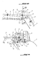
- Figures 13, 16-19 and 22 show the means allowing movement controlled in translation towards the front of the vehicle, from its closed position roof, sunroof panel 8 relatively to the side members 10 of the sunroof frame 9.
- These means include two lateral cables 41 extending longitudinally to the vehicle and capable of slide guided along the two respectively longitudinal members 10 of the sunroof frame 9, one piece 42 of the sunroof panel 8 being integral with the cross member 8a of the panel 8 and on the other hand of the corresponding cable 41.
- the part 42 in cross section approximately the shape of an L whose vertical leg at its upper end secured to the cross member 8a and the other leg is shaped so as to slide on a slide of conjugate shape 41a of the corresponding spar 10 towards the front or rear of the vehicle depending on the direction displacement imposed on cable 41 by a motor electric 43 housed in the vehicle body and coupled appropriately to the cables 41 which each slide in a part forming the longitudinal sheath of the spar corresponding 10.
- each drive piece 42 is kept pressed on the corresponding slide 41a by the associated cable 41 secured to the free end of the approximately horizontal leg of part 42.
- the panel 8 comprises on each side of the latter a lateral guide 43, which can be integral with the cross member 8a of the panel 8 and the end of which engages in a longitudinal groove the corresponding beam 10.
- the drive means controlled from the panel of the sunroof 8 being already known, it does not have to be more detailed.
- the sunroof frame 9 is fixed to the roof by fixing screws 44 visible in particular in Figures 21 and 22 and by gluing above the receiving housing in the body C of the engine 43, as shown in particular in Figure 16, to ensure its closure.
- the roof frame opening 9 is provided with a seal 45 with the panel 8 and protecting the drive motor 43 of the sunroof panel 8.
- a seal J is provided between the front part of panel 8 and the roof of the vehicle by being integral with the panel 8.
- FIG. 8 represents the means making it possible to lock the rear boot lid 1 to its position closing.
- These means include a locking mechanism unlockable with two locking fingers 46 joined respectively to the two frame uprights M of the rear trunk of the vehicle projecting from the outside of these and two lock boxes 47 housed in part 1, being integral with the face internal lining 4 in the upper part of this flap so as to allow the two fingers 46 to engage respectively in the two housings 47 through corresponding holes of the lining 4 to be each blocked in the housing 47 by a slide 48 mounted at movement controlled in translation in the housing 47 by an electric motor 49 also housed in the shutter 1 by being secured to the internal face of the lining 4.
- the electric motor 49 is connected to the slide 48 by a metal rod 50 and can be controlled by a actuator, such as a push button, located for example on the vehicle dashboard.
- Each locking finger 46 is fixed to the wall the corresponding amount M by a threaded rod 51 secured to finger 46, passing through this wall and fixed to this one by two nuts 52 blocked on each side of the wall.
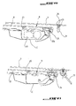
- Figure 23 shows the configuration according to which the rear flap 1 is locked in its position closing, the window 7 is locked in position folded down to flap 1 above it and the panel sunroof 8 is in its rear closed position of the vehicle roof.
- Figure 25 shows manual movement by the user of the flap 7 from its open position of the Figure 24 in a retracted position, not projecting in rear of the vehicle roof, above the sunroof 8.
- the flap 7 reaches its position furthest forward relative to the two guide rails 18, it is locked to these rails by the two rollers 17 self-locked in their respective locks 40.
- the user If the user wishes to configure the vehicle in pick-up, it drives the electric motor 43 cable drive 41 to move forward of the vehicle, the sunroof panel 8 as well as the window 7 locked to this panel to position la further forward from the vehicle shown in Figure 26.
- Figure 27 shows the rear flap 1 at its tilted position extending from floor 2 of the boot rear after activating the electric motor 49 to that it controls the movement of each slide 48 to its unlocking position of the locking finger 46 associated to allow the user to bring manually shutter 1 in the boot opening position back.
Applications Claiming Priority (2)
| Application Number | Priority Date | Filing Date | Title |
|---|---|---|---|
| FR0207020 | 2002-06-07 | ||
| FR0207020A FR2840579B1 (fr) | 2002-06-07 | 2002-06-07 | Dispositif formant volet de coffre arriere d'un vehicule automobile |
Publications (1)
| Publication Number | Publication Date |
|---|---|
| EP1369276A1 true EP1369276A1 (de) | 2003-12-10 |
Family
ID=29433344
Family Applications (1)
| Application Number | Title | Priority Date | Filing Date |
|---|---|---|---|
| EP03291312A Withdrawn EP1369276A1 (de) | 2002-06-07 | 2003-06-02 | Hintere Haube für Kraftfahrzeug |
Country Status (2)
| Country | Link |
|---|---|
| EP (1) | EP1369276A1 (de) |
| FR (1) | FR2840579B1 (de) |
Cited By (11)
| Publication number | Priority date | Publication date | Assignee | Title |
|---|---|---|---|---|
| DE10331692A1 (de) * | 2003-07-14 | 2005-02-10 | Bayerische Motoren Werke Ag | Vorrichtung zur Führung einer Heckklappe an einem Fahrzeug |
| FR2875442A1 (fr) * | 2004-09-22 | 2006-03-24 | Renault Sas | Ouvrant arriere |
| DE102005044239A1 (de) * | 2005-09-16 | 2007-03-22 | GM Global Technology Operations, Inc., Detroit | Heckklappenanordnung mit einer kombinierten translatorisch-rotatorischen Kinematik |
| DE102006051645A1 (de) * | 2006-11-02 | 2008-05-08 | Bayerische Motoren Werke Ag | Kraftfahrzeug mit einem Kofferraum |
| DE102006051647A1 (de) * | 2006-11-02 | 2008-05-08 | Bayerische Motoren Werke Ag | Kraftfahrzeug mit einem Kofferraum, der durch mindestens einen Kofferraumdeckel verschließbar ist |
| WO2008067629A1 (en) * | 2006-12-07 | 2008-06-12 | Salete Schio Soldatelli | Cover for a dump body of vehicles |
| US8292355B2 (en) | 2010-10-26 | 2012-10-23 | Miller Michael C | Vehicle roof with retractable windshield |
| FR3014761A1 (fr) * | 2013-12-16 | 2015-06-19 | Renault Sa | Systeme modulable pour vehicule permettant le chargement et le transport d'objets volumineux |
| DE102020117548A1 (de) | 2020-07-03 | 2022-01-05 | Dr. Ing. H.C. F. Porsche Aktiengesellschaft | Personenkraftwagen |
| CN114572125A (zh) * | 2022-03-24 | 2022-06-03 | 浙江吉利控股集团有限公司 | 车辆控制系统、车辆的控制方法及车辆 |
| CN114643840A (zh) * | 2022-03-24 | 2022-06-21 | 浙江吉利控股集团有限公司 | 车门、车门的控制方法及车辆 |
Families Citing this family (1)
| Publication number | Priority date | Publication date | Assignee | Title |
|---|---|---|---|---|
| FR2875180B1 (fr) | 2004-09-14 | 2007-01-12 | Peugeot Citroen Automobiles Sa | Vehicule automobile en particulier de type break comportant une porte arriere a deux ouvrants |
Citations (3)
| Publication number | Priority date | Publication date | Assignee | Title |
|---|---|---|---|---|
| DE19908253A1 (de) * | 1999-02-25 | 2000-09-07 | Audi Ag | Karosseriestruktur mit beweglichen Deckelelementen |
| DE19926474A1 (de) * | 1999-06-10 | 2000-12-14 | Bayerische Motoren Werke Ag | Kraftfahrzeug mit einem absenkbaren Verdeckkasten |
| EP1219479A1 (de) * | 2000-12-29 | 2002-07-03 | Webasto Vehicle Systems International GmbH | Schwenkbare und verschiebbare Heckscheibe |
-
2002
- 2002-06-07 FR FR0207020A patent/FR2840579B1/fr not_active Expired - Fee Related
-
2003
- 2003-06-02 EP EP03291312A patent/EP1369276A1/de not_active Withdrawn
Patent Citations (3)
| Publication number | Priority date | Publication date | Assignee | Title |
|---|---|---|---|---|
| DE19908253A1 (de) * | 1999-02-25 | 2000-09-07 | Audi Ag | Karosseriestruktur mit beweglichen Deckelelementen |
| DE19926474A1 (de) * | 1999-06-10 | 2000-12-14 | Bayerische Motoren Werke Ag | Kraftfahrzeug mit einem absenkbaren Verdeckkasten |
| EP1219479A1 (de) * | 2000-12-29 | 2002-07-03 | Webasto Vehicle Systems International GmbH | Schwenkbare und verschiebbare Heckscheibe |
Cited By (13)
| Publication number | Priority date | Publication date | Assignee | Title |
|---|---|---|---|---|
| DE10331692A1 (de) * | 2003-07-14 | 2005-02-10 | Bayerische Motoren Werke Ag | Vorrichtung zur Führung einer Heckklappe an einem Fahrzeug |
| FR2875442A1 (fr) * | 2004-09-22 | 2006-03-24 | Renault Sas | Ouvrant arriere |
| DE102005044239A1 (de) * | 2005-09-16 | 2007-03-22 | GM Global Technology Operations, Inc., Detroit | Heckklappenanordnung mit einer kombinierten translatorisch-rotatorischen Kinematik |
| DE102006051647B4 (de) * | 2006-11-02 | 2014-02-06 | Bayerische Motoren Werke Aktiengesellschaft | Kraftfahrzeug mit einem Kofferraum, der durch mindestens einen Kofferraumdeckel verschließbar ist |
| DE102006051645A1 (de) * | 2006-11-02 | 2008-05-08 | Bayerische Motoren Werke Ag | Kraftfahrzeug mit einem Kofferraum |
| DE102006051647A1 (de) * | 2006-11-02 | 2008-05-08 | Bayerische Motoren Werke Ag | Kraftfahrzeug mit einem Kofferraum, der durch mindestens einen Kofferraumdeckel verschließbar ist |
| WO2008067629A1 (en) * | 2006-12-07 | 2008-06-12 | Salete Schio Soldatelli | Cover for a dump body of vehicles |
| US8292355B2 (en) | 2010-10-26 | 2012-10-23 | Miller Michael C | Vehicle roof with retractable windshield |
| FR3014761A1 (fr) * | 2013-12-16 | 2015-06-19 | Renault Sa | Systeme modulable pour vehicule permettant le chargement et le transport d'objets volumineux |
| DE102020117548A1 (de) | 2020-07-03 | 2022-01-05 | Dr. Ing. H.C. F. Porsche Aktiengesellschaft | Personenkraftwagen |
| DE102020117548B4 (de) | 2020-07-03 | 2023-03-23 | Dr. Ing. H.C. F. Porsche Aktiengesellschaft | Personenkraftwagen |
| CN114572125A (zh) * | 2022-03-24 | 2022-06-03 | 浙江吉利控股集团有限公司 | 车辆控制系统、车辆的控制方法及车辆 |
| CN114643840A (zh) * | 2022-03-24 | 2022-06-21 | 浙江吉利控股集团有限公司 | 车门、车门的控制方法及车辆 |
Also Published As
| Publication number | Publication date |
|---|---|
| FR2840579B1 (fr) | 2005-04-01 |
| FR2840579A1 (fr) | 2003-12-12 |
Similar Documents
| Publication | Publication Date | Title |
|---|---|---|
| EP0860313B1 (de) | Steuervorrichtung zur Öffnung und Schliessung eines hinteren Kofferraums und hinteren Deckels eines Cabriofahrzeugs | |
| EP1240042B1 (de) | In einem kraftfahrzeugkofferraum versenkbares dach | |
| FR2574718A1 (fr) | Systeme de lunette arriere escamotable pour vehicule | |
| EP1369276A1 (de) | Hintere Haube für Kraftfahrzeug | |
| EP1272369B1 (de) | Vorrichtung eines öffnungfähigen dachs für cabrio-fahrzeug | |
| WO2009034272A2 (fr) | Dispositif elevateur pour fauteuil roulant | |
| EP1470012B1 (de) | Kofferraumdeckel für ein cabriofahrzeug mit faltverdeck | |
| EP1634745A1 (de) | Motorfahrzeug, insbesondere Kombiwagen mit einer Hintertür mit zwei Flügeln | |
| EP1328416B1 (de) | Versenkbares fahrzeugdach mit drei längselementen | |
| EP1635026A1 (de) | Rückstell- und halterungsvorrichtung einer Heckklappe eines Kraftfahrzeuges mit zwei Flügeln | |
| EP0884218B1 (de) | Bewegbare Trittstufe für ein Fahrzeug | |
| FR2806969A1 (fr) | Vehicule automobile a lunette escamotable | |
| FR2699126A1 (fr) | Porte latérale de véhicule automobile et véhicule automobile équipé d'une telle porte. | |
| FR2736380A1 (fr) | Mecanisme d'articulation d'un element mobile, notamment d'une portiere de vehicule automobile | |
| FR2793754A1 (fr) | Hayon arriere pour vehicule automobile | |
| EP1151880A1 (de) | Umstellbare Tür für Motorfahrzeug | |
| FR2797656A1 (fr) | Agencement d'une porte coulissante sur un vehicule | |
| FR2734208A1 (fr) | Agencement d'une porte laterale sur un vehicule automobile | |
| FR2809679A1 (fr) | Dispositif formant ouvrant, tel qu'une porte ou un hayon, d'un vehicule automobile | |
| EP1077147B1 (de) | Schiebetüranordnung an einem Fahrzeug | |
| EP1180076B1 (de) | Im kofferraum eines kraftfahrzeugs versenkbares dach | |
| FR2809677A1 (fr) | Dispositif formant ouvrant, tel qu'une porte ou un hayon, d'un vehicule automobile | |
| EP1053899A1 (de) | Heckklappe für Kraftfahrzeug | |
| FR2660009A1 (fr) | Dispositif de guidage d'une porte coulissante et escamotable de vehicule, et porte coulissante equipee d'un tel dispositif. | |
| FR2676402A1 (fr) | Porte de vehicule automobile a vitre pivotante. |
Legal Events
| Date | Code | Title | Description |
|---|---|---|---|
| PUAI | Public reference made under article 153(3) epc to a published international application that has entered the european phase |
Free format text: ORIGINAL CODE: 0009012 |
|
| AK | Designated contracting states |
Kind code of ref document: A1 Designated state(s): AT BE BG CH CY CZ DE DK EE ES FI FR GB GR HU IE IT LI LU MC NL PT RO SE SI SK TR |
|
| AX | Request for extension of the european patent |
Extension state: AL LT LV MK |
|
| 17P | Request for examination filed |
Effective date: 20040524 |
|
| AKX | Designation fees paid |
Designated state(s): AT BE BG CH CY CZ DE DK EE ES FI FR GB GR HU IE IT LI LU MC NL PT RO SE SI SK TR |
|
| STAA | Information on the status of an ep patent application or granted ep patent |
Free format text: STATUS: THE APPLICATION IS DEEMED TO BE WITHDRAWN |
|
| 18D | Application deemed to be withdrawn |
Effective date: 20100105 |