EP1369276A1 - Rear bootlid for automobile - Google Patents
Rear bootlid for automobile Download PDFInfo
- Publication number
- EP1369276A1 EP1369276A1 EP03291312A EP03291312A EP1369276A1 EP 1369276 A1 EP1369276 A1 EP 1369276A1 EP 03291312 A EP03291312 A EP 03291312A EP 03291312 A EP03291312 A EP 03291312A EP 1369276 A1 EP1369276 A1 EP 1369276A1
- Authority
- EP
- European Patent Office
- Prior art keywords
- roof
- window
- vehicle
- flap
- panel
- Prior art date
- Legal status (The legal status is an assumption and is not a legal conclusion. Google has not performed a legal analysis and makes no representation as to the accuracy of the status listed.)
- Withdrawn
Links
Images


Classifications
-
- B—PERFORMING OPERATIONS; TRANSPORTING
- B60—VEHICLES IN GENERAL
- B60J—WINDOWS, WINDSCREENS, NON-FIXED ROOFS, DOORS, OR SIMILAR DEVICES FOR VEHICLES; REMOVABLE EXTERNAL PROTECTIVE COVERINGS SPECIALLY ADAPTED FOR VEHICLES
- B60J5/00—Doors
- B60J5/10—Doors arranged at the vehicle rear
- B60J5/101—Doors arranged at the vehicle rear for non-load transporting vehicles, i.e. family cars including vans
- B60J5/102—Doors arranged at the vehicle rear for non-load transporting vehicles, i.e. family cars including vans comprising door or part of door being pivotable downwards about horizontal axis to open position
- B60J5/103—Doors arranged at the vehicle rear for non-load transporting vehicles, i.e. family cars including vans comprising door or part of door being pivotable downwards about horizontal axis to open position where lower door part moves independently from other door structures, e.g. by being hinged on the vehicle body
-
- B—PERFORMING OPERATIONS; TRANSPORTING
- B60—VEHICLES IN GENERAL
- B60J—WINDOWS, WINDSCREENS, NON-FIXED ROOFS, DOORS, OR SIMILAR DEVICES FOR VEHICLES; REMOVABLE EXTERNAL PROTECTIVE COVERINGS SPECIALLY ADAPTED FOR VEHICLES
- B60J1/00—Windows; Windscreens; Accessories therefor
- B60J1/18—Windows; Windscreens; Accessories therefor arranged at the vehicle rear
- B60J1/1838—Windows; Windscreens; Accessories therefor arranged at the vehicle rear movable for non-convertible vehicles, including vehicles with versatile load area
- B60J1/1846—Windows; Windscreens; Accessories therefor arranged at the vehicle rear movable for non-convertible vehicles, including vehicles with versatile load area where the window can slide
- B60J1/1869—Windows; Windscreens; Accessories therefor arranged at the vehicle rear movable for non-convertible vehicles, including vehicles with versatile load area where the window can slide to an end position parallel to roof
-
- B—PERFORMING OPERATIONS; TRANSPORTING
- B60—VEHICLES IN GENERAL
- B60J—WINDOWS, WINDSCREENS, NON-FIXED ROOFS, DOORS, OR SIMILAR DEVICES FOR VEHICLES; REMOVABLE EXTERNAL PROTECTIVE COVERINGS SPECIALLY ADAPTED FOR VEHICLES
- B60J1/00—Windows; Windscreens; Accessories therefor
- B60J1/18—Windows; Windscreens; Accessories therefor arranged at the vehicle rear
- B60J1/1838—Windows; Windscreens; Accessories therefor arranged at the vehicle rear movable for non-convertible vehicles, including vehicles with versatile load area
- B60J1/1876—Windows; Windscreens; Accessories therefor arranged at the vehicle rear movable for non-convertible vehicles, including vehicles with versatile load area where the window is pivotable relative to a stationary axis
- B60J1/1884—Windows; Windscreens; Accessories therefor arranged at the vehicle rear movable for non-convertible vehicles, including vehicles with versatile load area where the window is pivotable relative to a stationary axis about a horizontal axis
-
- B—PERFORMING OPERATIONS; TRANSPORTING
- B60—VEHICLES IN GENERAL
- B60J—WINDOWS, WINDSCREENS, NON-FIXED ROOFS, DOORS, OR SIMILAR DEVICES FOR VEHICLES; REMOVABLE EXTERNAL PROTECTIVE COVERINGS SPECIALLY ADAPTED FOR VEHICLES
- B60J10/00—Sealing arrangements
- B60J10/80—Sealing arrangements specially adapted for opening panels, e.g. doors
-
- B—PERFORMING OPERATIONS; TRANSPORTING
- B60—VEHICLES IN GENERAL
- B60J—WINDOWS, WINDSCREENS, NON-FIXED ROOFS, DOORS, OR SIMILAR DEVICES FOR VEHICLES; REMOVABLE EXTERNAL PROTECTIVE COVERINGS SPECIALLY ADAPTED FOR VEHICLES
- B60J5/00—Doors
- B60J5/10—Doors arranged at the vehicle rear
- B60J5/101—Doors arranged at the vehicle rear for non-load transporting vehicles, i.e. family cars including vans
- B60J5/107—Doors arranged at the vehicle rear for non-load transporting vehicles, i.e. family cars including vans constructional details, e.g. about door frame, panels, materials used, reinforcements
Definitions
- the present invention relates to a device forming a rear trunk flap of a motor vehicle.
- tailgate as a component for closing the rear trunk of a motor vehicle.
- the object of the present invention is to eliminate the above disadvantage by proposing a device forming rear boot lid of a motor vehicle allowing the depositing of objects in the rear boot without be forced to fully open the rear door.
- the boot flap device rear of a motor vehicle fitted with a window rear which can be arranged above the rear flap substantially as an extension of this component occupying its rear boot closing position, is characterized in that the rear window is pivotally mounted at the rear part of the roof of the vehicle along an axis transverse to the latter opposite the flap and can pivot between its closed rear trunk position as an extension of the closed flap and a position opening approximately in extension of the pavilion freeing up the space above the closed shutter to access the trunk.
- the rear window can slide from guided in translation along the pavilion above from it towards the front of the vehicle from its open position to a stowed position retracted not protruding from the rear of the vehicle.
- the rear window is mounted pivoting to the roof via two hinges on each side of the glass and whose axes of articulation are coaxial transversely to the vehicle, the movable element of each hinge being fixed to the glass in the vicinity of its edge opposite the rear flap while the fixed element of the hinge is fitted with a rolling roller housed in a longitudinal side guide rail of the roof for allow bilaterally guided sliding of the rear window along the guide rails.
- the rear window can be blocked relative to the guide rails in its most advanced retracted position on the rails by means of automatic locking.
- the pavilion is equipped with a rear roof panel opening with displacement controlled in translation and bilaterally guided relative to the pavilion between a closed roof position and an advanced position on the opening pavilion of the rear part of the pavilion and the rear window guide rails are fixed each side of the rear roof sun panel under this to allow the rear window to slide relative to the panel above it from the window open position when the panel occupies its closed position of the pavilion until the rear window is locked relative to the panel at its advanced position above it by the automatic locking means.
- the sunroof panel can drive kinematically the rear window towards the front of the vehicle in the locked position of the window relative to the panel when the latter is moved to its position advanced opening of the rear part of the roof for partially configure the vehicle in pick-up.
- the rear sunroof panel is mounted bilaterally guided on a frame with side rails of integral guidance of the pavilion.
- each articulation hinge of the rear window is in the form of a yoke located above of the rear sunroof panel which has a lateral tab external to the panel at the end lower of which the rotation roller is mounted bearing housed in its guide rail below the sunroof panel.
- the rear window can be locked at its closed position to the rear shutter closed by a unlockable locking mechanism comprising a locking finger secured to the window when crossing this and a locking box fixed in the shutter rear and in which can engage the finger of locking to be blocked by a slide movement controlled in the housing by a motor electric housed in the rear flap.
- a unlockable locking mechanism comprising a locking finger secured to the window when crossing this and a locking box fixed in the shutter rear and in which can engage the finger of locking to be blocked by a slide movement controlled in the housing by a motor electric housed in the rear flap.
- the locking finger is integral with its opposite end of an external operating handle located near the lower edge of the rear window substantially in the middle of it.
- the rear flap is hinged on its edge lower than the vehicle body by two hinges spaced whose axes of articulation are coaxial and transverse to the longitudinal axis of the vehicle to allow the shutter to swing to its open position approximately as an extension of the vehicle floor when the rear window is at least in its position opening.
- Back cover can be locked in position closing the vehicle body by a mechanism unlockable lock with two locking fingers interlocking secured respectively to the two uprights of the vehicle body delimiting the opening of the trunk rear protruding from these uprights and two locking boxes fixed in the rear flap of each side of it at its top opposite to the articulation of the flap and in each of which can engage a locking finger to be blocked by a displacement slide controlled in the housing by an electric motor housed in the rear housing.
- Two lateral gas cylinders are mounted articulated between the vehicle body and the rear window at its ends opposite its articulation to the roof for allow controlled pivoting of the glass to its open position in extension of the roof.
- the sunroof rear panel is movable along the pavilion by an electric motor controlled by distance and connected to the panel by means drive.
- rear roof panel type motor vehicle opening which can slide in translation of the part rear of the vehicle roof towards the front of it and rear trunk closing flap that can pivot from its closed position to its open position in rear trunk floor extension but it is of course it can apply to any other type vehicle such as for example a roof vehicle with no movable sunroof panel.
- the motor vehicle is fitted with a flap 1 for closing the rear boot of the vehicle and pivotally mounted by its lower edge to the vehicle body following a transverse joint allowing it to switch from its closed position to trunk in its open position at which shutter 1 is located approximately in the extension of the floor 2 of the rear boot of the vehicle.
- the shutter 1 is formed by an outer panel in sheet 3 and a lining 4 secured to the outer panel 3 while being turned towards the interior of the trunk in shutter closed position 1.
- the articulation of the part 1 to the body C of the vehicle consists of two articulation hinges 5 arranged symmetrically at the longitudinal median plane of the vehicle, the movable element 5a of each hinge 5 being fixed, for example by welding or by screwing, to an end wall of the lining 4 of the shutter 1 while the fixed element 5b of the hinge 5 is fixed, for example by welding or screwing, to the body C of the vehicle substantially at floor 2 of the rear trunk, the two hinges 5c between the two movable and fixed elements 5a and 5b of the hinges 5 being coaxial and extending transversely to vehicle.
- a 5d transverse joint is fixed to the body at the level of the rear transverse edge of the rear boot for seal between the lower part of the shutter 1 and the trunk.
- the rear flap 1 is retained in its position opening by two lateral pairs of articulated arms 6 like a compass, one of the arms of each pair being fixed by its end in an articulated manner to the amount M of body C of the delimiting vehicle the rear opening of the trunk while the other arm of this pair is fixed by its opposite end to the wall corresponding side of the lining 4 substantially at middle of it.
- the rear flap 1 can be locked in position closed at the vehicle body by a mechanism controlled locking which will be described later.
- the rear flap 1 In its closed position, the rear flap 1 is surmounted by a window 7 enabling closure complete with the rear trunk of the vehicle.
- the sunroof panel 8 which can be produced made of a translucent material, plastic or sheet metal, is slidably mounted in a controlled manner translation on a frame 9 with side rails 10 and cross member 11 connecting the side members and integral with the vehicle roof so as to move the panel 8 in before or behind the next vehicle you want open or close the rear roof section overlooking the rear trunk of the vehicle.
- Two longitudinal roof bars 12 integral with each side of the vehicle roof can be provided.
- the shutter window 7 is mounted swivel at the rear of the vehicle roof along an axis transverse to the opposite vehicle of the rear flap 1 and allowing the window 7 to pivot from its closed position, flap 1 closed, to a opening position approximately as an extension of flag and, more precisely in extension of the panel sunroof 8 when present, so to free up the space above the closed shutter 1 normally occupied by the window 7 in order to access the rear boot and deposit objects there without having to open the shutter 1, as shown in Figures 2 and 24.
- the shutter glass 7 can slide from guided way in translation towards the front of the vehicle the along the pavilion above it from its open position to a stowed position retracted, that is to say no longer protruding from the rear of the vehicle, above the rear pavilion or sun roof panel correspondent 8 when present, as shown in Figures 3 and 25.
- the shutter glass 7 is pivotally mounted at vehicle roof, particularly at the roof panel opening 8, via two hinges hinge 13 spaced on each side of the window 7 and whose articulation axes 14 are coaxial transversely to the vehicle.
- the moving element or pivoting 15 of each articulation hinge 13 is fixed to the window 7 in the vicinity of its transverse edge opposite the flap 1 while the fixed element 16 of the hinge 13, relative to which the element can pivot mobile 15, is mounted on the sunroof panel 8 and equipped with a roller 17 housed and retained in a lateral longitudinal guide rail 18 fixed below the corresponding side of the sunroof panel 8 to allow bilaterally guided sliding of the window 7 along the guide rails 18.
- each element 16 of articulation hinge 13 is in form of yoke above the lateral side corresponding to the sunroof panel 8, the yoke 16 comprising a lateral tab 19 external to the panel 8 the lower end of which extends below this panel rotates about a transverse axis 20 integral with the lug 19 the roller 17.
- guide rail 18 of each roller 17 has a lower part opposite panel 8 with section substantially U-shaped cross section in which can move the roller 17 and the side wall of this rail connected to the U-shaped lower part and opposite leg 19, ends at the top by a wall substantially at a right angle for fixing the rail 18 under panel 8 via bolts fixing 21.
- a protective seal 22 is interposed between the upper face of the sunroof panel 8 in sliding contact with it and element 16 of each hinge 13 by being integral with this element 16.
- Each mobile element 15 of a hinge hinge 13 is fixed to the window 7 by at least one fixing stud 23.
- two lateral cylinders 25, preferably of the gas type are provided, the cylinder 26 of each cylinder 25 being hingedly attached at its end to the vehicle body while the piston rod 27 of this cylinder is hinged at its end opposite the window 7 by means of a piece of support 28 fixed behind the window 7 in the vicinity of its corresponding corner opposite the hinge 13 by a bolt 29, a seal 30 being secured to the body C of the vehicle in the vicinity of the amount corresponding to the framing of the opening of the rear trunk to seal the glass 7 to its closed position along its lateral side corresponding.
- a protective stop 28a is fixed to the support piece 28 and is supported on the panel 8 when the window 7 is in position on the panel 8.
- the window 7 can be locked in its position of closing, to the rear flap closed 1 by a mechanism unlockable lock, preferably remotely, especially by the driver.
- this locking includes a locking finger 31 secured to the window 7 by means of a nut 32 and a threaded rod 33 passing perpendicularly the window 7 in the vicinity of its lower edge and at middle of it.
- An external operating handle 34 is fixed by screwing on the threaded rod 33 while being locked in abutment on the corresponding external face of the window 7.
- the locking mechanism further comprises a housing 35 fixed in the rear flap in part top of it between the outer panel 1 and the lining 4 and a slide element 36 is mounted mobile in rectilinear translation in the housing 35 in a finger 31 unlocking direction under the control an electric motor 37 fixed in shutter 1 on a reinforcement portion 38 secured to the internal face of the lining 4, the electric motor 37 being connected to the slide 36 by a metal rod 39.
- the motor electric 37 can be remotely controlled by a device actuation, such as a push button, located at the vehicle dashboard.
- the locking finger 31 crosses a hole made in the upper part of the external panel 3 of shutter 1 and engages transversely in the housing 35 to be blocked therein, in window 7 closed position, by the end conformed to this effect of the slide 36.
- the rod 39 moves in translation the slide 36 relative to the housing 35 in a direction disengaging the opposite end of the slide 36 of finger 31 to release the latter and allow a user to manually rotate the window 7 to its open position by pulling on the operating handle 24.
- An elastic member such as a coil tension spring (not shown) can be interposed between the housing 35 and the slide 26 for recall the latter to its locked position so that by inserting finger 31 again, this the latter is automatically blocked in the box 35 by the free end of the slide 36.
- a joint transverse sealing 39 is fixed on the rim upper transverse of flap 1 to ensure the seal between the window 7 and the shutter 1 and between the lining 4 and the outer panel 1 of this flap.
- the rear window 7 can be automatically blocked relative to the guide rails 18 at its most advanced retracted position on these rails by locking means for retaining the window 7 relative to the roof when the vehicle is moving.
- These locking means can be constituted each by a skate-like organ or part elastically deformable or integrated into each rail 18 above the corresponding roller 17 towards the front end of the rail to block the flap 17 when it contacts the locking member. So, when element 16 of each hinge 13 moves towards the front of the vehicle relative to the rail corresponding 18, the roller 17 engage in the body 40 for its relatively blocking to rail 18.
- This locking member could have cross section the shape of a large inverted V whose the curved free ends will be fixed, by example by welding, under an upper wall rail 18 so that the roller bearing 17 can engage elastically between the two branches of the inverted V of this organ.
- the locking means 40 allow the panel sunroof 8, when moved in translation relative to the roof towards the front of the vehicle, also drive the window 7 to this position to ensure the vehicle pick-up configuration.
- Figures 13, 16-19 and 22 show the means allowing movement controlled in translation towards the front of the vehicle, from its closed position roof, sunroof panel 8 relatively to the side members 10 of the sunroof frame 9.
- These means include two lateral cables 41 extending longitudinally to the vehicle and capable of slide guided along the two respectively longitudinal members 10 of the sunroof frame 9, one piece 42 of the sunroof panel 8 being integral with the cross member 8a of the panel 8 and on the other hand of the corresponding cable 41.
- the part 42 in cross section approximately the shape of an L whose vertical leg at its upper end secured to the cross member 8a and the other leg is shaped so as to slide on a slide of conjugate shape 41a of the corresponding spar 10 towards the front or rear of the vehicle depending on the direction displacement imposed on cable 41 by a motor electric 43 housed in the vehicle body and coupled appropriately to the cables 41 which each slide in a part forming the longitudinal sheath of the spar corresponding 10.
- each drive piece 42 is kept pressed on the corresponding slide 41a by the associated cable 41 secured to the free end of the approximately horizontal leg of part 42.
- the panel 8 comprises on each side of the latter a lateral guide 43, which can be integral with the cross member 8a of the panel 8 and the end of which engages in a longitudinal groove the corresponding beam 10.
- the drive means controlled from the panel of the sunroof 8 being already known, it does not have to be more detailed.
- the sunroof frame 9 is fixed to the roof by fixing screws 44 visible in particular in Figures 21 and 22 and by gluing above the receiving housing in the body C of the engine 43, as shown in particular in Figure 16, to ensure its closure.
- the roof frame opening 9 is provided with a seal 45 with the panel 8 and protecting the drive motor 43 of the sunroof panel 8.
- a seal J is provided between the front part of panel 8 and the roof of the vehicle by being integral with the panel 8.
- FIG. 8 represents the means making it possible to lock the rear boot lid 1 to its position closing.
- These means include a locking mechanism unlockable with two locking fingers 46 joined respectively to the two frame uprights M of the rear trunk of the vehicle projecting from the outside of these and two lock boxes 47 housed in part 1, being integral with the face internal lining 4 in the upper part of this flap so as to allow the two fingers 46 to engage respectively in the two housings 47 through corresponding holes of the lining 4 to be each blocked in the housing 47 by a slide 48 mounted at movement controlled in translation in the housing 47 by an electric motor 49 also housed in the shutter 1 by being secured to the internal face of the lining 4.
- the electric motor 49 is connected to the slide 48 by a metal rod 50 and can be controlled by a actuator, such as a push button, located for example on the vehicle dashboard.
- Each locking finger 46 is fixed to the wall the corresponding amount M by a threaded rod 51 secured to finger 46, passing through this wall and fixed to this one by two nuts 52 blocked on each side of the wall.
- Figure 23 shows the configuration according to which the rear flap 1 is locked in its position closing, the window 7 is locked in position folded down to flap 1 above it and the panel sunroof 8 is in its rear closed position of the vehicle roof.
- Figure 25 shows manual movement by the user of the flap 7 from its open position of the Figure 24 in a retracted position, not projecting in rear of the vehicle roof, above the sunroof 8.
- the flap 7 reaches its position furthest forward relative to the two guide rails 18, it is locked to these rails by the two rollers 17 self-locked in their respective locks 40.
- the user If the user wishes to configure the vehicle in pick-up, it drives the electric motor 43 cable drive 41 to move forward of the vehicle, the sunroof panel 8 as well as the window 7 locked to this panel to position la further forward from the vehicle shown in Figure 26.
- Figure 27 shows the rear flap 1 at its tilted position extending from floor 2 of the boot rear after activating the electric motor 49 to that it controls the movement of each slide 48 to its unlocking position of the locking finger 46 associated to allow the user to bring manually shutter 1 in the boot opening position back.
Abstract
Description
La présente invention concerne un dispositif formant volet de coffre arrière d'un véhicule automobile.The present invention relates to a device forming a rear trunk flap of a motor vehicle.
On connaít l'utilisation du hayon en tant que volet de fermeture du coffre arrière d'un véhicule automobile.We know the use of the tailgate as a component for closing the rear trunk of a motor vehicle.
Cependant, cette configuration connue du volet arrière a pour inconvénient majeur de nécessiter l'ouverture complète du hayon pour déposer des objets dans le coffre arrière quelles que soient leurs dimensions.However, this known configuration of the flap rear has the major drawback of requiring full opening of the tailgate to deposit objects in the trunk regardless of their dimensions.
La présente invention a pour but d'éliminer l'inconvénient ci-dessus en proposant un dispositif formant volet de coffre arrière d'un véhicule automobile permettant la dépose d'objets dans le coffre arrière sans être obligé d'ouvrir complètement le volet arrière.The object of the present invention is to eliminate the above disadvantage by proposing a device forming rear boot lid of a motor vehicle allowing the depositing of objects in the rear boot without be forced to fully open the rear door.
A cet effet, le dispositif formant volet de coffre arrière d'un véhicule automobile, équipé d'une vitre arrière pouvant être disposée au-dessus du volet arrière sensiblement en prolongement de ce volet occupant sa position de fermeture du coffre arrière, est caractérisé en ce que la vitre arrière est montée pivotante à la partie arrière du pavillon du véhicule suivant un axe transversal à ce dernier à l'opposé du volet et peut pivoter entre sa position de fermeture du coffre arrière en prolongement du volet fermé et une position d'ouverture approximativement en prolongement du pavillon permettant de libérer l'espace au-dessus du volet fermé pour accéder au coffre arrière.To this end, the boot flap device rear of a motor vehicle, fitted with a window rear which can be arranged above the rear flap substantially as an extension of this component occupying its rear boot closing position, is characterized in that the rear window is pivotally mounted at the rear part of the roof of the vehicle along an axis transverse to the latter opposite the flap and can pivot between its closed rear trunk position as an extension of the closed flap and a position opening approximately in extension of the pavilion freeing up the space above the closed shutter to access the trunk.
Avantageusement, la vitre arrière peut coulisser de façon guidée en translation le long du pavillon au-dessus de celui-ci vers l'avant du véhicule à partir de sa position d'ouverture jusqu'à une position rangée escamotée non en saillie de l'arrière du véhicule.Advantageously, the rear window can slide from guided in translation along the pavilion above from it towards the front of the vehicle from its open position to a stowed position retracted not protruding from the rear of the vehicle.
De préférence, la vitre arrière est montée pivotante au pavillon par l'intermédiaire de deux charnières d'articulation situées de chaque côté de la vitre et dont les axes d'articulation sont coaxiaux transversalement au véhicule, l'élément mobile de chaque charnière étant fixé à la vitre au voisinage de son bord opposé au volet arrière tandis que l'élément fixe de la charnière est équipé d'un galet de roulement logé dans un rail de guidage longitudinal latéral du pavillon pour permettre le coulissement bilatéralement guidé de la vitre arrière le long des rails de guidage.Preferably, the rear window is mounted pivoting to the roof via two hinges on each side of the glass and whose axes of articulation are coaxial transversely to the vehicle, the movable element of each hinge being fixed to the glass in the vicinity of its edge opposite the rear flap while the fixed element of the hinge is fitted with a rolling roller housed in a longitudinal side guide rail of the roof for allow bilaterally guided sliding of the rear window along the guide rails.
La vitre arrière peut être bloquée relativement aux rails de guidage à sa position escamotée la plus avancée sur les rails par des moyens de verrouillage automatique.The rear window can be blocked relative to the guide rails in its most advanced retracted position on the rails by means of automatic locking.
Le pavillon est équipé d'un panneau arrière de toit ouvrant à déplacement commandé en translation et bilatéralement guidé relativement au pavillon entre une position fermée du pavillon et une position avancée sur le pavillon d'ouverture de la partie arrière du pavillon et les rails de guidage de la vitre arrière sont fixés de chaque côté du panneau arrière du toit ouvrant sous celui-ci pour permettre à la vitre arrière de coulisser relativement au panneau au-dessus de celui-ci à partir de la position d'ouverture de la vitre lorsque le panneau occupe sa position de fermeture du pavillon jusqu'à ce que la vitre arrière soit bloquée relativement au panneau à sa position avancée au-dessus de celui-ci par les moyens de verrouillage automatique.The pavilion is equipped with a rear roof panel opening with displacement controlled in translation and bilaterally guided relative to the pavilion between a closed roof position and an advanced position on the opening pavilion of the rear part of the pavilion and the rear window guide rails are fixed each side of the rear roof sun panel under this to allow the rear window to slide relative to the panel above it from the window open position when the panel occupies its closed position of the pavilion until the rear window is locked relative to the panel at its advanced position above it by the automatic locking means.
Le panneau de toit ouvrant peut entraíner cinématiquement la vitre arrière vers l'avant du véhicule en position verrouillée de la vitre relativement au panneau lorsque ce dernier est déplacé à sa position avancée d'ouverture de la partie arrière du pavillon pour configurer partiellement le véhicule en pick-up.The sunroof panel can drive kinematically the rear window towards the front of the vehicle in the locked position of the window relative to the panel when the latter is moved to its position advanced opening of the rear part of the roof for partially configure the vehicle in pick-up.
Le panneau arrière de toit ouvrant est monté bilatéralement guidé sur un cadre à longerons latéraux de guidage solidaire du pavillon.The rear sunroof panel is mounted bilaterally guided on a frame with side rails of integral guidance of the pavilion.
L'élément fixe de chaque charnière d'articulation de la vitre arrière est en forme de chape située au-dessus du panneau arrière de toit ouvrant et qui comporte une patte latérale externe au panneau à l'extrémité inférieure de laquelle est monté à rotation le galet de roulement logé dans son rail de guidage en-dessous du panneau de toit ouvrant.The fixed element of each articulation hinge of the rear window is in the form of a yoke located above of the rear sunroof panel which has a lateral tab external to the panel at the end lower of which the rotation roller is mounted bearing housed in its guide rail below the sunroof panel.
La vitre arrière peut être verrouillée à sa position de fermeture au volet arrière fermé par un mécanisme de verrouillage déverrouillable comprenant un doigt de verrouillage solidaire de la vitre en traversant celle-ci et un boítier de verrouillage fixé dans le volet arrière et dans lequel peut s'engager le doigt de verrouillage pour y être bloqué par un coulisseau à déplacement commandé dans le boítier par un moteur électrique logé dans le volet arrière.The rear window can be locked at its closed position to the rear shutter closed by a unlockable locking mechanism comprising a locking finger secured to the window when crossing this and a locking box fixed in the shutter rear and in which can engage the finger of locking to be blocked by a slide movement controlled in the housing by a motor electric housed in the rear flap.
Le doigt de verrouillage est solidaire à son extrémité opposée d'une poignée externe de manoeuvre située au voisinage du bord inférieur de la vitre arrière sensiblement au milieu de celle-ci.The locking finger is integral with its opposite end of an external operating handle located near the lower edge of the rear window substantially in the middle of it.
Le volet arrière est monté articulé à son bord inférieur à la caisse du véhicule par deux charnières espacées dont les axes d'articulation sont coaxiaux et transversaux à l'axe longitudinal du véhicule pour permettre au volet de basculer à sa position d'ouverture approximativement en prolongement du plancher du véhicule lorsque la vitre arrière est au moins à sa position d'ouverture.The rear flap is hinged on its edge lower than the vehicle body by two hinges spaced whose axes of articulation are coaxial and transverse to the longitudinal axis of the vehicle to allow the shutter to swing to its open position approximately as an extension of the vehicle floor when the rear window is at least in its position opening.
Le volet arrière peut être verrouillé à sa position de fermeture à la caisse du véhicule par un mécanisme de verrouillage déverrouillable comprenant deux doigts de verrouillage solidaires respectivement des deux montants de la caisse du véhicule délimitant l'ouverture du coffre arrière en faisant saillie de ces montants et deux boítiers de verrouillage fixés dans le volet arrière de chaque côté de celui-ci à sa partie supérieure opposée à l'articulation du volet et dans chacun desquels peut s'engager un doigt de verrouillage pour y être bloqué par un coulisseau à déplacement commandé dans le boítier par un moteur électrique logé dans le boítier arrière.Back cover can be locked in position closing the vehicle body by a mechanism unlockable lock with two locking fingers interlocking secured respectively to the two uprights of the vehicle body delimiting the opening of the trunk rear protruding from these uprights and two locking boxes fixed in the rear flap of each side of it at its top opposite to the articulation of the flap and in each of which can engage a locking finger to be blocked by a displacement slide controlled in the housing by an electric motor housed in the rear housing.
Deux vérins latéraux à gaz sont montés articulés entre la caisse du véhicule et la vitre arrière à ses extrémités opposées à son articulation au pavillon pour permettre le pivotement contrôlé de la vitre à sa position d'ouverture en prolongement du pavillon.Two lateral gas cylinders are mounted articulated between the vehicle body and the rear window at its ends opposite its articulation to the roof for allow controlled pivoting of the glass to its open position in extension of the roof.
Le panneau arrière du toit ouvrant est déplaçable le long du pavillon par un moteur électrique commandé à distance et relié au panneau par des moyens d'entraínement.The sunroof rear panel is movable along the pavilion by an electric motor controlled by distance and connected to the panel by means drive.
L'invention sera mieux comprise, et d'autres buts, caractéristiques, détails et avantages de celle-ci apparaítront plus clairement dans la description explicative qui va suivre faite en référence aux dessins schématiques annexés donnés uniquement à titre d'exemple illustrant un mode de réalisation de l'invention et dans lesquels :
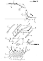
- la figure 1 est une vue en coupe dans le plan médian longitudinal de la partie arrière d'un véhicule automobile et représentant le volet arrière de l'invention en position de fermeture du coffre arrière du véhicule ;
- la figure 2 est une vue semblable à celle de la figure 1 et représentant la vitre du volet arrière en position d'ouverture d'accès au coffre arrière du véhicule ;
- la figure 3 montre le coulissement de la vitre arrière vers l'avant du véhicule à partir de sa position d'ouverture de la figure 2 jusqu'à une position surplombant un panneau arrière de toit ouvrant du véhicule occupant sa position de fermeture ;
- la figure 4 représente le déplacement vers l'avant du véhicule de l'ensemble constitué par le panneau de toit ouvrant et la vitre arrière à partir de la position représentée à la figure 3 ;
- la figure 5 correspond à la figure 4 et représente le volet arrière déverrouillé en position sensiblement horizontale ;
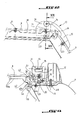
- la figure 6 est une vue en perspective éclatée des différents composants associés au volet arrière, à la vitre arrière et au panneau mobile du pavillon du véhicule ;
- la figure 7 est une vue en section horizontale suivant la ligne VII-VII de la figure 6 ;
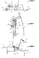
- la figure 8 est une vue en section suivant la ligne VIII-VIII de la figure 23 du mécanisme de verrouillage du volet arrière à l'un des montants de la caisse du véhicule délimitant l'ouverture du coffre arrière ;
- la figure 9 est une vue en section suivant la ligne IX-IX en figure 24 et représentant l'une des charnières d'articulation de la partie inférieure du volet arrière à la caisse du véhicule ;
- la figure 10 est une vue agrandie de la partie cerclée en X de la figure 1 ;
- la figure 11 est une vue en coupe agrandie de la partie cerclée en XI de la figure 1 ;
- la figure 12 est une vue en section dans un plan vertical longitudinal passant par une charnière d'articulation de la vitre arrière au pavillon du véhicule ;
- la figure 13 est une vue en section suivant la ligne XIII-XIII de la figure 12 ;
- la figure 14 est une vue partielle en section dans le plan médian longitudinal du véhicule et représentant la vitre arrière située au-dessus du panneau du toit ouvrant lequel occupe sa position de fermeture de la partie arrière du pavillon du véhicule ;
- la figure 15 est une vue agrandie de la partie cerclée en XV de la figure 3 ;
- la figure 16 est une vue en section dans le plan médian longitudinal du véhicule et représentant l'ensemble constitué par le panneau de toit ouvrant et la vitre arrière en position la plus en avant du véhicule pour conformer ce dernier en pick-up ;
- la figure 17 est une vue en section dans un plan vertical longitudinal du véhicule passant par l'un des vérins à gaz de la vitre arrière et représentant l'ensemble constitué par le panneau de toit ouvrant de la vitre arrière à la même position qu'en figure 16 ;
- la figure 18 est une vue en section dans le plan médian longitudinal du véhicule de la partie avant du panneau de toit ouvrant en position fermée ;
- la figure 19 est une vue semblable à celle de la figure 18 et représentant la vitre arrière de volet en position au-dessus du panneau de toit ouvrant ;
- la figure 20 est une vue en section dans le plan vertical médian d'une charnière d'articulation de la vitre arrière de volet disposée au-dessus du panneau de toit ouvrant ;
- la figure 21 est une vue en section suivant la ligne XXI-XXI de la figure 20 ;
- la figure 22 est une vue en section semblable à celle de la figure 21 lorsque l'ensemble formé par le panneau de toit ouvrant et la vitre est en position la plus en avant du véhicule pour le configurer en pick-up ;
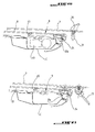
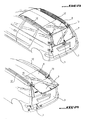
- la figure 23 est une vue en perspective du véhicule représentant le volet de coffre arrière, la vitre arrière et le panneau de toit ouvrant en position fermée ;
- la figure 24 est une vue en perspective du véhicule représentant la vitre du volet de coffre arrière en position d'ouverture d'accès au coffre arrière avec le volet arrière en position fermée ;
- la figure 25 est une vue en perspective du véhicule représentant la vitre de volet arrière en position rangée escamotée au-dessus du panneau de toit ouvrant arrière ;
- la figure 26 est une vue en perspective du véhicule représentant l'ensemble constitué par la vitre de volet arrière et le panneau de toit ouvrant en position la plus en avant du véhicule pour le configurer en pick-up ; et
- la figure 27 est une vue en perspective du véhicule représentant le volet arrière en position ouverte.
- Figure 1 is a sectional view in the longitudinal median plane of the rear part of a motor vehicle and showing the rear flap of the invention in the closed position of the rear boot of the vehicle;
- Figure 2 is a view similar to that of Figure 1 and showing the window of the rear flap in the open position for access to the rear boot of the vehicle;
- FIG. 3 shows the sliding of the rear window towards the front of the vehicle from its open position in FIG. 2 to a position overhanging a rear sunroof panel of the vehicle occupying its closed position;
- Figure 4 shows the forward movement of the vehicle of the assembly constituted by the sunroof panel and the rear window from the position shown in Figure 3;
- Figure 5 corresponds to Figure 4 and shows the rear flap unlocked in a substantially horizontal position;
- Figure 6 is an exploded perspective view of the various components associated with the rear flap, the rear window and the movable panel of the vehicle roof;
- Figure 7 is a horizontal sectional view along line VII-VII of Figure 6;
- Figure 8 is a sectional view along line VIII-VIII of Figure 23 of the rear shutter locking mechanism to one of the amounts of the vehicle body defining the opening of the rear trunk;
- Figure 9 is a sectional view along line IX-IX in Figure 24 and showing one of the articulation hinges of the lower part of the rear flap to the vehicle body;
- Figure 10 is an enlarged view of the X-rimmed portion of Figure 1;
- Figure 11 is an enlarged sectional view of the part circled in XI of Figure 1;
- Figure 12 is a sectional view in a longitudinal vertical plane passing through a hinge of articulation of the rear window to the roof of the vehicle;
- Figure 13 is a sectional view along line XIII-XIII of Figure 12;
- Figure 14 is a partial sectional view in the longitudinal median plane of the vehicle and showing the rear window located above the panel of the sunroof which occupies its closed position of the rear part of the roof of the vehicle;
- Figure 15 is an enlarged view of the part circled in XV of Figure 3;
- Figure 16 is a sectional view in the longitudinal median plane of the vehicle and showing the assembly consisting of the sunroof panel and the rear window in the most forward position of the vehicle to conform the latter in pick-up;
- FIG. 17 is a sectional view in a longitudinal vertical plane of the vehicle passing through one of the gas cylinders of the rear window and representing the assembly constituted by the sunroof panel of the rear window in the same position as in Figure 16;
- Figure 18 is a sectional view in the longitudinal median plane of the vehicle of the front part of the sunroof panel in the closed position;
- Figure 19 is a view similar to that of Figure 18 and showing the rear window pane in position above the sunroof panel;
- Figure 20 is a sectional view in the median vertical plane of a hinge of articulation of the rear window pane disposed above the sunroof panel;
- Figure 21 is a sectional view along line XXI-XXI of Figure 20;
- Figure 22 is a sectional view similar to that of Figure 21 when the assembly formed by the sunroof panel and the window is in the most forward position of the vehicle to configure it in pick-up;
- FIG. 23 is a perspective view of the vehicle showing the rear boot flap, the rear window and the sunroof panel in the closed position;
- FIG. 24 is a perspective view of the vehicle showing the window of the rear boot flap in the position for opening access to the rear boot with the rear flap in the closed position;
- FIG. 25 is a perspective view of the vehicle showing the rear pane window in the retracted stowed position above the rear sunroof panel;
- FIG. 26 is a perspective view of the vehicle representing the assembly constituted by the rear shutter window and the sunroof panel in the most forward position of the vehicle to configure it as a pick-up; and
- Figure 27 is a perspective view of the vehicle showing the rear flap in the open position.
L'invention va être décrite en référence à un véhicule automobile du type à panneau arrière de toit ouvrant pouvant coulisser en translation de la partie arrière du pavillon du véhicule vers l'avant de celui-ci et à volet de fermeture du coffre arrière pouvant pivoter de sa position de fermeture à sa position d'ouverture en prolongement du plancher du coffre arrière, mais il est bien entendu qu'elle peut s'appliquer à tout autre type de véhicule tel que par exemple un véhicule à pavillon ne comportant pas de panneau mobile de toit ouvrant.The invention will be described with reference to a rear roof panel type motor vehicle opening which can slide in translation of the part rear of the vehicle roof towards the front of it and rear trunk closing flap that can pivot from its closed position to its open position in rear trunk floor extension but it is of course it can apply to any other type vehicle such as for example a roof vehicle with no movable sunroof panel.
En se reportant aux figures, le véhicule automobile
est équipé d'un volet 1 de fermeture du coffre arrière du
véhicule et monté pivotant par son bord inférieur à la
caisse du véhicule suivant une articulation transversale
lui permettant de basculer de sa position de fermeture du
coffre à sa position d'ouverture de celui-ci à laquelle
le volet 1 se trouve approximativement dans le
prolongement du plancher 2 du coffre arrière du véhicule.Referring to the figures, the motor vehicle
is fitted with a
Le volet 1 est formé par un panneau extérieur en
tôle 3 et une doublure 4 solidaire du panneau extérieur 3
en étant tournée vers l'intérieur du coffre arrière en
position fermée du volet 1.The
Comme représenté à la figure 9, l'articulation du
volet 1 à la caisse C du véhicule est constituée par deux
charnières d'articulation 5 disposées symétriquement au
plan médian longitudinal du véhicule, l'élément mobile 5a
de chaque charnière 5 étant fixé, par exemple par soudage
ou par vissage, à une paroi d'extrémité de la doublure 4
du volet 1 tandis que l'élément fixe 5b de la charnière 5
est fixé, par exemple par soudage ou vissage, à la caisse
C du véhicule sensiblement au niveau du plancher 2 du
coffre arrière, les deux axes d'articulation 5c entre les
deux éléments mobiles et fixes 5a et 5b des charnières 5
étant coaxiaux et s'étendant transversalement au
véhicule. Un joint transversal 5d est fixé à la caisse au
niveau du bord arrière transversal du coffre arrière pour
assurer l'étanchéité entre la partie inférieure du volet
1 et le coffre.As shown in Figure 9, the articulation of the
Le volet arrière 1 est retenu à sa position
d'ouverture par deux paires latérales de bras articulés 6
à la manière d'un compas, l'un des bras de chaque paire
étant fixé par son extrémité de façon articulée au
montant M de la caisse C du véhicule délimitant
l'ouverture arrière du coffre tandis que l'autre bras de
cette paire est fixé par son extrémité opposée à la paroi
latérale correspondante de la doublure 4 sensiblement au
milieu de celle-ci.The
Le volet arrière 1 peut être verrouillé en position
fermée à la caisse du véhicule par un mécanisme de
verrouillage commandé qui sera décrit ultérieurement.The
A sa position fermée, le volet arrière 1 est
surmonté d'une vitre 7 permettant d'assurer une fermeture
complète du coffre arrière du véhicule.In its closed position, the
Le panneau de toit ouvrant 8, qui peut être réalisé
en un matériau translucide, en matière plastique ou en
tôle, est monté coulissant de façon commandée en
translation sur un cadre 9 à longerons latéraux 10 et
traverse 11 de liaison des longerons et solidaire du
pavillon de véhicule de façon à déplacer le panneau 8 en
avant ou en arrière du véhicule suivant que l'on souhaite
ouvrir ou fermer la partie de pavillon arrière
surplombant le coffre arrière du véhicule.The
Deux barres de toit longitudinales 12 solidaires de chaque côté du pavillon du véhicule peuvent être prévues.Two longitudinal roof bars 12 integral with each side of the vehicle roof can be provided.
Selon l'invention, la vitre de volet 7 est montée
pivotante à la partie arrière du pavillon du véhicule
suivant un axe transversal au véhicule situé à l'opposé
du volet arrière 1 et permettant à la vitre 7 de pivoter
de sa position de fermeture, volet 1 fermé, à une
position d'ouverture approximativement en prolongement du
pavillon et, plus précisément en prolongement du panneau
de toit ouvrant 8 lorsque celui-ci est présent, de façon
à libérer l'espace au-dessus du volet fermé 1 normalement
occupé par la vitre 7 afin d'accéder au coffre arrière et
y déposer des objets sans être obligé d'ouvrir le volet
1, comme représenté aux figures 2 et 24.According to the invention, the
En outre, la vitre de volet 7 peut coulisser de
façon guidée en translation vers l'avant du véhicule le
long du pavillon au-dessus de celui-ci à partir de sa
position d'ouverture jusqu'à une position rangée
escamotée, c'est-à-dire ne faisant plus saillie de
l'arrière du véhicule, au-dessus de la partie arrière
correspondante du pavillon ou du panneau de toit ouvrant
8 lorsque présent, comme représenté aux figures 3 et 25.In addition, the
Enfin, l'entraínement commandé du panneau de toit
ouvrant 8 vers l'avant du véhicule provoque le
déplacement concomitant de la vitre de volet 7
verrouillée au-dessus du panneau 8 pour dégager la partie
arrière du véhicule et le conformer en pick-up comme
représenté aux figures 4 et 26.Finally, the controlled training of the roof panel
opening 8 towards the front of the vehicle causes the
concomitant movement of the
La structure et le fonctionnement des différents composants du dispositif de l'invention permettant les différentes configurations ci-dessus du véhicule vont être détaillées ci-dessous.The structure and operation of the different components of the device of the invention allowing the different above vehicle configurations are going be detailed below.
La vitre de volet 7 est montée pivotante au
pavillon du véhicule, notamment au panneau de toit
ouvrant 8, par l'intermédiaire de deux charnières
d'articulation 13 espacées situées de chaque côté de la
vitre 7 et dont les axes d'articulation 14 sont coaxiaux
transversalement au véhicule. L'élément mobile ou
pivotant 15 de chaque charnière d'articulation 13 est
fixé à la vitre 7 au voisinage de son bord transversal
opposé au volet 1 tandis que l'élément fixe 16 de la
charnière 13, par rapport auquel peut pivoter l'élément
mobile 15, est monté sur le panneau de toit ouvrant 8 et
équipé d'un galet de roulement 17 logé et retenu dans un
rail de guidage longitudinal latéral 18 fixé en-dessous
du côté latéral correspondant du panneau de toit ouvrant
8 pour permettre le coulissement bilatéralement guidé de
la vitre 7 le long des rails de guidage 18.The
Comme cela ressort mieux notamment de la figure 13,
chaque élément 16 de charnière d'articulation 13 est en
forme de chape située au-dessus du côté latéral
correspondant du panneau de toit ouvrant 8, la chape 16
comportant une patte latérale 19 externe au panneau 8
dont l'extrémité inférieure, se prolongeant en-dessous de
ce panneau porte à rotation autour d'un axe transversal
20 solidaire de la patte 19 le galet de roulement 17. Le
rail de guidage 18 de chaque galet de roulement 17 a une
partie inférieure opposée au panneau 8 à section
transversale sensiblement en forme de U dans laquelle
peut se déplacer le galet 17 et la paroi latérale de ce
rail raccordée à la partie inférieure en forme de U et
opposée à la patte 19, se termine en partie supérieure
par une paroi sensiblement à angle droit de fixation du
rail 18 sous le panneau 8 par l'intermédiaire de boulons
de fixation 21. Un joint de protection 22 est interposé
entre la face supérieure du panneau de toit ouvrant 8 en
contact glissant avec celle-ci et l'élément 16 de chaque
charnière 13 en étant solidaire de cet élément 16. Chaque
élément mobile 15 d'une charnière d'articulation 13 est
fixé à la vitre 7 par au moins un goujon de fixation 23.As is better illustrated in particular in FIG. 13,
each
En position de fermeture de la vitre 7 au-dessus du
volet fermé 1, l'étanchéité entre le bord transversal
supérieur de la vitre 7 et le pavillon du véhicule est
assurée par un joint transversal d'étanchéité 24 chaussé
sur le bord transversal arrière du panneau 8 occupant sa
position fermée du pavillon et fixé à une traverse 8a
solidaire du panneau 8 sous celui-ci (figure 10).In the closed position of the
Pour assurer le pivotement contrôlé en douceur de
la vitre 7 de sa position de fermeture à sa position
d'ouverture, deux vérins latéraux 25, de préférence du
type à gaz, sont prévus, le cylindre 26 de chaque vérin
25 étant fixé de façon articulée à son extrémité à la
caisse du véhicule tandis que la tige de piston 27 de ce
vérin est fixée de façon articulée à son extrémité
opposée à la vitre 7 par l'intermédiaire d'une pièce de
support 28 fixée derrière la vitre 7 au voisinage de son
coin correspondant opposé à la charnière d'articulation
13 par un boulon 29, un joint d'étanchéité 30 étant
solidaire de la caisse C du véhicule au voisinage du
montant correspondant à l'encadrement de l'ouverture du
coffre arrière pour assurer l'étanchéité de la vitre 7 à
sa position de fermeture le long de son côté latéral
correspondant. Une butée de protection 28a est fixée à la
pièce de support 28 et est en appui sur le panneau 8
lorsque la vitre 7 est en position sur le panneau 8.To ensure smooth controlled pivoting of
the
La vitre 7 peut être verrouillée à sa position de
fermeture, au volet arrière fermé 1 par un mécanisme de
verrouillage déverrouillable, de préférence à distance,
notamment par le conducteur.The
Comme représenté en figure 11, ce mécanisme de
verrouillage comprend un doigt de verrouillage 31
solidaire de la vitre 7 par l'intermédiaire d'un écrou 32
et d'une tige filetée 33 traversant perpendiculairement
la vitre 7 au voisinage de son bord inférieur et au
milieu de celui-ci. Une poignée externe de manoeuvre 34
est fixée par vissage sur la tige filetée 33 en étant
bloquée en appui sur la face externe correspondante de la
vitre 7. Le mécanisme de verrouillage comprend en outre
un boítier 35 fixé dans le volet arrière en partie
supérieure de celui-ci entre le panneau externe 1 et la
doublure 4 et un élément formant coulisseau 36 est monté
mobile en translation rectiligne dans le boítier 35 dans
un sens de déverouillage du doigt 31 sous la commande
d'un moteur électrique 37 fixé dans le volet 1 sur une
partie de renfort 38 solidaire de la face interne de la
doublure 4, le moteur électrique 37 étant relié au
coulisseau 36 par une tringle métallique 39. Le moteur
électrique 37 peut être commandé à distance par un organe
d'actionnement, tel qu'un bouton poussoir, situé au
tableau de bord du véhicule. Le doigt de verrouillage 31
traverse un perçage réalisé en partie supérieure du
panneau externe 3 du volet 1 et s'engage transversalement
dans le boítier 35 pour être bloqué dans celui-ci, en
position de fermeture de la vitre 7, par l'extrémité
conformée à cet effet du coulisseau 36. Ainsi, lorsque le
moteur électrique 37 est actionné, la tringle 39 déplace
en translation le coulisseau 36 relativement au boítier
35 dans un sens désengageant l'extrémité opposée du
coulisseau 36 du doigt 31 pour libérer ce dernier et
permettre à un utilisateur de faire pivoter manuellement
la vitre 7 à sa position d'ouverture en tirant sur la
poignée de manoeuvre 24. Un organe élastique, tel qu'un
ressort hélicoïdal de traction (non représenté) peut être
interposé entre le boítier 35 et le coulisseau 26 pour
rappeler ce dernier à sa position de verrouillage de
façon qu'en introduisant à nouveau le doigt 31, ce
dernier soit automatiquement bloqué dans le boítier 35
par l'extrémité libre du coulisseau 36. Un joint
transversal d'étanchéité 39 est fixé sur le rebord
transversal supérieur du volet 1 pour assurer
l'étanchéité entre la vitre 7 et le volet 1 et entre la
doublure 4 et le panneau extérieur 1 de ce volet.As shown in Figure 11, this
locking includes a locking
La vitre arrière 7 peut être automatiquement
bloquée relativement aux rails de guidage 18 à sa
position escamotée la plus avancée sur ces rails par des
moyens de verrouillage permettant de retenir la vitre 7
relativement au pavillon lorsque le véhicule se déplace.The
Ces moyens de verrouillage peuvent être constitués
chacun par un organe du genre patin ou une partie
conformée élastiquement déformable ou intégré à chaque
rail 18 au-dessus du galet de roulement correspondant 17
vers l'extrémité avant du rail pour bloquer le volet 17
lorsqu'il contacte l'organe de verrouillage. Ainsi,
lorsque l'élément 16 de chaque charnière 13 se déplace
vers l'avant du véhicule relativement au rail
correspondant 18, le galet de roulement 17 vient
s'engager dans l'organe 40 pour son blocage relativement
au rail 18. Cet organe de blocage pourrait présenter en
section transversale la forme d'un grand V renversé dont
les extrémités libres recourbées seront fixées, par
exemple par soudage, sous une paroi supérieure
correspondante du rail 18 de façon que le galet de
roulement 17 puisse s'engager à force élastiquement entre
les deux branches du V renversé de cet organe.These locking means can be constituted
each by a skate-like organ or part
elastically deformable or integrated into each
Les moyens de verrouillage 40 permettent au panneau
de toit ouvrant 8, lorsque déplacé en translation
relativement au pavillon vers l'avant du véhicule,
d'entraíner également la vitre 7 vers cette position pour
assurer la configuration en pick-up du véhicule.The locking means 40 allow the
Les figures 13, 16-19 et 22 représentent les moyens
permettant le déplacement commandé en translation vers
l'avant du véhicule, à partir de sa position de fermeture
du pavillon, du panneau de toit ouvrant 8 relativement
aux longerons 10 du cadre de toit ouvrant 9.Figures 13, 16-19 and 22 show the means
allowing movement controlled in translation towards
the front of the vehicle, from its closed position
roof,
Ces moyens comprennent deux câbles latéraux 41
s'étendant longitudinalement au véhicule et pouvant
coulisser de façon guidée respectivement le long des deux
longerons 10 du cadre de toit ouvrant 9, une pièce
d'entraínement 42 du panneau de toit ouvrant 8 étant
solidaire d'une part de la traverse 8a du panneau 8 et
d'autre part du câble correspondant 41. La pièce
d'entraínement 42 présente en section transversale
approximativement la forme d'un L dont la jambe verticale
a son extrémité supérieure solidaire de la traverse 8a et
l'autre jambe est conformée de façon à coulisser sur une
coulisse de forme conjuguée 41a du longeron correspondant
10 vers l'avant ou l'arrière du véhicule suivant le sens
de déplacement imposé au câble 41 par un moteur
électrique 43 logé dans la caisse du véhicule et accouplé
de façon appropriée aux câbles 41 qui coulissent chacun
dans une partie formant fourreau longitudinal du longeron
correspondant 10. Chaque pièce d'entraínement 42 est
maintenue en appui sur la coulisse correspondant 41a par
le câble associé 41 solidaire de l'extrémité libre de la
jambe approximativement horizontale de la pièce 42. Pour
assurer un guidage bilatéral du panneau de toit ouvrant 8
relativement au cadre de toit ouvrant 9, le panneau 8
comporte de chaque côté de celui-ci un guide latéral 43,
qui peut être solidaire de la traverse 8a du panneau 8 et
dont l'extrémité s'engage dans une rainure longitudinale
du longeron correspondant 10.These means include two
Les moyens d'entraínement commandés du panneau du
toit ouvrant 8 étant déjà connus, il n'ont pas à être
davantage détaillés.The drive means controlled from the panel of the
Le cadre de toit ouvrant 9 est fixé au pavillon par
des vis de fixation 44 visibles notamment aux figures 21
et 22 et par collage au-dessus du logement de réception
dans la caisse C du moteur 43, comme représenté notamment
au figure 16, pour assurer sa fermeture. Le cadre du toit
ouvrant 9 est pourvu d'un joint d'étanchéité 45 avec le
panneau 8 et protégeant le moteur d'entraínement 43 du
panneau de toit ouvrant 8. Un joint d'étanchéité J est
prévu entre la partie avant du panneau 8 et le pavillon
du véhicule en étant solidaire du panneau 8.The
La figure 8 représente les moyens permettant de
verrouiller le volet de coffre arrière 1 à sa position de
fermeture.FIG. 8 represents the means making it possible to
lock the
Ces moyens comprennent un mécanisme de verrouillage
déverrouillable comportant deux doigts de verrouillage 46
solidaires respectivement des deux montants d'encadrement
M du coffre arrière du véhicule en faisant saillie à
l'extérieur de ceux-ci et deux boítiers de verrouillage
47 logés dans le volet 1 en étant solidaires de la face
interne de la doublure 4 en partie supérieure de ce volet
de façon à permettre aux deux doigts 46 de s'engager
respectivement dans les deux boítiers 47 au travers de
perçages correspondants de la doublure 4 pour être chacun
bloqué dans le boítier 47 par un coulisseau 48 monté à
déplacement commandé en translation dans le boítier 47
par un moteur électrique 49 également logé dans le volet
1 en étant solidarisé à la face interne de la garniture
4. Le moteur électrique 49 est relié au coulisseau 48 par
une tringle métallique 50 et peut être commandé par un
organe d'actionnement, tel qu'un bouton poussoir, situé
par exemple au tableau de bord du véhicule.These means include a locking mechanism
unlockable with two locking
Chaque doigt de verrouillage 46 est fixé à la paroi
du montant correspondant M par une tige filetée 51
solidaire du doigt 46, traversant cette paroi et fixé à
celle-ci par deux écrous 52 bloqués de chaque côté de la
paroi.Each locking
Le fonctionnement du dispositif formant volet de coffre arrière ressort déjà de la description qui en a été faite ci-dessus et va être maintenant expliqué en référence aux figures 23 à 27.The operation of the shutter device rear trunk is already apparent from the description which has been made above and will now be explained in reference to Figures 23 to 27.
La figure 23 représente la configuration selon
laquelle le volet arrière 1 est verrouillé à sa position
de fermeture, la vitre 7 est verrouillée en position
rabattue au volet 1 au-dessus de celui-ci et le panneau
de toit ouvrant 8 est à sa position arrière de fermeture
du pavillon du véhicule.Figure 23 shows the configuration according to
which the
Lorsqu'un utilisateur souhaite déposer des objets
dans le coffre arrière sans avoir à ouvrir le volet 1, il
commande par l'organe d'actionnement approprié le moteur
électrique 37 de façon à désengager le coulisseau 36 de
sa position de verrouillage du doigt de verrouillage 31.
Ensuite, l'utilisateur manoeuvre la poignée 34 pour faire
pivoter la vitre 7 à sa position d'ouverture dite
entrebaillée représentée en figure 24 et à laquelle la
vitre 7 se trouve approximativement en prolongement du
pavillon du véhicule. Le pivotement de la vitre 7 à sa
position d'ouverture est assisté par les deux vérins à
gaz 25.When a user wishes to deposit objects
in the trunk without having to open the
La figure 25 représente le déplacement manuel par
l'utilisateur du volet 7 de sa position d'ouverture de la
figure 24 à une position escamotée, non en saillie en
arrière du pavillon du véhicule, au-dessus du panneau de
toit ouvrant 8. Lorsque le volet 7 arrive à sa position
la plus en avant relativement aux deux rails de guidage
18, celui-ci est verrouillé à ces rails par les deux
galets de roulement 17 autobloqués dans leurs organes de
verrouillage respectifs 40.Figure 25 shows manual movement by
the user of the
Si l'utilisateur souhaite configurer le véhicule en
pick-up, il actionne le moteur électrique 43
d'entraínement des câbles 41 pour déplacer vers l'avant
du véhicule le panneau de toit ouvrant 8 ainsi que la
vitre 7 verrouillée à ce panneau jusqu'à la position la
plus en avant du véhicule représentée en figure 26.If the user wishes to configure the vehicle in
pick-up, it drives the
La figure 27 représente le volet arrière 1 à sa
position basculée en prolongement du plancher 2 du coffre
arrière après avoir actionné le moteur électrique 49 pour
qu'il commande le déplacement de chaque coulisseau 48 à
sa position de déverrouillage du doigt du verrouillage 46
associé pour permettre à l'utilisateur d'amener
manuellement le volet 1 en position d'ouverture du coffre
arrière.Figure 27 shows the
Claims (12)
Applications Claiming Priority (2)
| Application Number | Priority Date | Filing Date | Title |
|---|---|---|---|
| FR0207020A FR2840579B1 (en) | 2002-06-07 | 2002-06-07 | DEVICE FORMING REAR CHASSIS COMPONENT OF A MOTOR VEHICLE |
| FR0207020 | 2002-06-07 |
Publications (1)
| Publication Number | Publication Date |
|---|---|
| EP1369276A1 true EP1369276A1 (en) | 2003-12-10 |
Family
ID=29433344
Family Applications (1)
| Application Number | Title | Priority Date | Filing Date |
|---|---|---|---|
| EP03291312A Withdrawn EP1369276A1 (en) | 2002-06-07 | 2003-06-02 | Rear bootlid for automobile |
Country Status (2)
| Country | Link |
|---|---|
| EP (1) | EP1369276A1 (en) |
| FR (1) | FR2840579B1 (en) |
Cited By (11)
| Publication number | Priority date | Publication date | Assignee | Title |
|---|---|---|---|---|
| DE10331692A1 (en) * | 2003-07-14 | 2005-02-10 | Bayerische Motoren Werke Ag | Device for guiding of hatchback door on vehicle has upper lying pivot axis which with opening of hatchback door is guided along roof of vehicle in guide for displacement of hatchback door |
| FR2875442A1 (en) * | 2004-09-22 | 2006-03-24 | Renault Sas | Motor vehicle`s rear opening, has lower leaf, constituted of two parts, forming extension of floor pan of trunk of motor vehicle when in open position, and partly closing opening of trunk when in closed position |
| DE102005044239A1 (en) * | 2005-09-16 | 2007-03-22 | GM Global Technology Operations, Inc., Detroit | Tailgate arrangement with a combined translatory-rotary kinematics |
| DE102006051645A1 (en) * | 2006-11-02 | 2008-05-08 | Bayerische Motoren Werke Ag | Motor vehicle with a trunk |
| DE102006051647A1 (en) * | 2006-11-02 | 2008-05-08 | Bayerische Motoren Werke Ag | Motor vehicle, has upper and lower luggage compartment covers adjusted along axes running in transverse direction from closed condition into open condition, where upper luggage compartment cover has horizontal position in open condition |
| WO2008067629A1 (en) * | 2006-12-07 | 2008-06-12 | Salete Schio Soldatelli | Cover for a dump body of vehicles |
| US8292355B2 (en) | 2010-10-26 | 2012-10-23 | Miller Michael C | Vehicle roof with retractable windshield |
| FR3014761A1 (en) * | 2013-12-16 | 2015-06-19 | Renault Sa | MODULAR SYSTEM FOR VEHICLE FOR LOADING AND TRANSPORTING VOLUMINOUS OBJECTS |
| DE102020117548A1 (en) | 2020-07-03 | 2022-01-05 | Dr. Ing. H.C. F. Porsche Aktiengesellschaft | Passenger cars |
| CN114572125A (en) * | 2022-03-24 | 2022-06-03 | 浙江吉利控股集团有限公司 | Vehicle control system, vehicle control method and vehicle |
| CN114643840A (en) * | 2022-03-24 | 2022-06-21 | 浙江吉利控股集团有限公司 | Vehicle door, vehicle door control method and vehicle |
Families Citing this family (1)
| Publication number | Priority date | Publication date | Assignee | Title |
|---|---|---|---|---|
| FR2875180B1 (en) | 2004-09-14 | 2007-01-12 | Peugeot Citroen Automobiles Sa | MOTOR VEHICLE PARTICULARLY OF THE BREAK TYPE HAVING A REAR DOOR WITH TWO OPENERS |
Citations (3)
| Publication number | Priority date | Publication date | Assignee | Title |
|---|---|---|---|---|
| DE19908253A1 (en) * | 1999-02-25 | 2000-09-07 | Audi Ag | Body structure with movable cover elements |
| DE19926474A1 (en) * | 1999-06-10 | 2000-12-14 | Bayerische Motoren Werke Ag | High construction private motor vehicle has state in which with folding top box located on level with closed roof the vehicle presents closed structure and even in this raised position of folding top is functional and drivable |
| EP1219479A1 (en) * | 2000-12-29 | 2002-07-03 | Webasto Vehicle Systems International GmbH | Liftable and slidable rear window |
-
2002
- 2002-06-07 FR FR0207020A patent/FR2840579B1/en not_active Expired - Fee Related
-
2003
- 2003-06-02 EP EP03291312A patent/EP1369276A1/en not_active Withdrawn
Patent Citations (3)
| Publication number | Priority date | Publication date | Assignee | Title |
|---|---|---|---|---|
| DE19908253A1 (en) * | 1999-02-25 | 2000-09-07 | Audi Ag | Body structure with movable cover elements |
| DE19926474A1 (en) * | 1999-06-10 | 2000-12-14 | Bayerische Motoren Werke Ag | High construction private motor vehicle has state in which with folding top box located on level with closed roof the vehicle presents closed structure and even in this raised position of folding top is functional and drivable |
| EP1219479A1 (en) * | 2000-12-29 | 2002-07-03 | Webasto Vehicle Systems International GmbH | Liftable and slidable rear window |
Cited By (13)
| Publication number | Priority date | Publication date | Assignee | Title |
|---|---|---|---|---|
| DE10331692A1 (en) * | 2003-07-14 | 2005-02-10 | Bayerische Motoren Werke Ag | Device for guiding of hatchback door on vehicle has upper lying pivot axis which with opening of hatchback door is guided along roof of vehicle in guide for displacement of hatchback door |
| FR2875442A1 (en) * | 2004-09-22 | 2006-03-24 | Renault Sas | Motor vehicle`s rear opening, has lower leaf, constituted of two parts, forming extension of floor pan of trunk of motor vehicle when in open position, and partly closing opening of trunk when in closed position |
| DE102005044239A1 (en) * | 2005-09-16 | 2007-03-22 | GM Global Technology Operations, Inc., Detroit | Tailgate arrangement with a combined translatory-rotary kinematics |
| DE102006051647B4 (en) * | 2006-11-02 | 2014-02-06 | Bayerische Motoren Werke Aktiengesellschaft | Motor vehicle with a trunk, which is closed by at least one trunk lid |
| DE102006051645A1 (en) * | 2006-11-02 | 2008-05-08 | Bayerische Motoren Werke Ag | Motor vehicle with a trunk |
| DE102006051647A1 (en) * | 2006-11-02 | 2008-05-08 | Bayerische Motoren Werke Ag | Motor vehicle, has upper and lower luggage compartment covers adjusted along axes running in transverse direction from closed condition into open condition, where upper luggage compartment cover has horizontal position in open condition |
| WO2008067629A1 (en) * | 2006-12-07 | 2008-06-12 | Salete Schio Soldatelli | Cover for a dump body of vehicles |
| US8292355B2 (en) | 2010-10-26 | 2012-10-23 | Miller Michael C | Vehicle roof with retractable windshield |
| FR3014761A1 (en) * | 2013-12-16 | 2015-06-19 | Renault Sa | MODULAR SYSTEM FOR VEHICLE FOR LOADING AND TRANSPORTING VOLUMINOUS OBJECTS |
| DE102020117548A1 (en) | 2020-07-03 | 2022-01-05 | Dr. Ing. H.C. F. Porsche Aktiengesellschaft | Passenger cars |
| DE102020117548B4 (en) | 2020-07-03 | 2023-03-23 | Dr. Ing. H.C. F. Porsche Aktiengesellschaft | passenger cars |
| CN114572125A (en) * | 2022-03-24 | 2022-06-03 | 浙江吉利控股集团有限公司 | Vehicle control system, vehicle control method and vehicle |
| CN114643840A (en) * | 2022-03-24 | 2022-06-21 | 浙江吉利控股集团有限公司 | Vehicle door, vehicle door control method and vehicle |
Also Published As
| Publication number | Publication date |
|---|---|
| FR2840579B1 (en) | 2005-04-01 |
| FR2840579A1 (en) | 2003-12-12 |
Similar Documents
| Publication | Publication Date | Title |
|---|---|---|
| EP0860313B1 (en) | Opening and closing control device for rear luggage compartment and rear deck for convertible vehicle | |
| EP1240042B1 (en) | Roof that can be retracted into the trunk of a vehicle | |
| FR2574718A1 (en) | RETRACTABLE REAR WINDOW SYSTEM FOR VEHICLE | |
| EP1369276A1 (en) | Rear bootlid for automobile | |
| EP1272369B1 (en) | Sliding roof system for convertible vehicle | |
| EP2178484A2 (en) | Lift device for a rolling chair | |
| EP1470012B1 (en) | Rear boot hood for an open-top vehicle with a folding roof | |
| EP1634745A1 (en) | Motor vehicle in particular estate car comprising a rear door with two closure members | |
| EP1328416B1 (en) | Retractable roof for vehicle, comprising three longitudinal elements | |
| EP1635026A1 (en) | Return and support device of a rear door of a vehicle having two wings | |
| EP0884218B1 (en) | Movable foot step for a vehicle | |
| FR2806969A1 (en) | Automobile has retractable rear window hinged to roof rear connected by balancing actuator to bodywork upright and retracted toward vehicle front by two cables | |
| FR2699126A1 (en) | Side door for motor vehicle - has sliding and rotating action using guide rails and pivot point giving opening movement in place of door wheelchair | |
| FR2736380A1 (en) | Motor vehicle door hinge - comprises guides consisting of first hinge whose fixed part is carried by bodywork and second hinge whose fixed part pivots about hub, fixed to door, and arm connecting hinge moving parts | |
| FR2793754A1 (en) | Hatchback for car has inner and outer panels, and articulation system restraining interference between bumper and outer panel when hatchback is opened | |
| EP1151880A1 (en) | Convertible door for motor vehicle | |
| FR2797656A1 (en) | Door hinge assembly for motor vehicle has movable body panel section to allow free movement of door hinge | |
| FR2734208A1 (en) | Door mechanism for vehicle side door | |
| FR2809679A1 (en) | Opening device, for vehicle, consists of upper and lower panel, with upper panel hinged to vehicle by top edge and lower panel linked to upper by mechanism to guide opening along specific trajectory | |
| EP1077147B1 (en) | Sliding door assembly on a vehicle | |
| EP1180076B1 (en) | Retractable roof in the rear boot of a coverable vehicle | |
| FR2809677A1 (en) | Door or hatchback for vehicle, consists of upper and lower panel, with upper panel hinged to vehicle by top edge and lower panel linked to upper by mechanism to fold completely under upper panel | |
| EP1053899A1 (en) | Tailgate for motor vehicle | |
| FR2660009A1 (en) | Device for guiding a sliding and retractable vehicle door and sliding door equipped with such a device | |
| FR2676402A1 (en) | Motor vehicle door with pivoting glass |
Legal Events
| Date | Code | Title | Description |
|---|---|---|---|
| PUAI | Public reference made under article 153(3) epc to a published international application that has entered the european phase |
Free format text: ORIGINAL CODE: 0009012 |
|
| AK | Designated contracting states |
Kind code of ref document: A1 Designated state(s): AT BE BG CH CY CZ DE DK EE ES FI FR GB GR HU IE IT LI LU MC NL PT RO SE SI SK TR |
|
| AX | Request for extension of the european patent |
Extension state: AL LT LV MK |
|
| 17P | Request for examination filed |
Effective date: 20040524 |
|
| AKX | Designation fees paid |
Designated state(s): AT BE BG CH CY CZ DE DK EE ES FI FR GB GR HU IE IT LI LU MC NL PT RO SE SI SK TR |
|
| STAA | Information on the status of an ep patent application or granted ep patent |
Free format text: STATUS: THE APPLICATION IS DEEMED TO BE WITHDRAWN |
|
| 18D | Application deemed to be withdrawn |
Effective date: 20100105 |