EP0743500A2 - Brûleur à récupération - Google Patents
Brûleur à récupération Download PDFInfo
- Publication number
- EP0743500A2 EP0743500A2 EP96106942A EP96106942A EP0743500A2 EP 0743500 A2 EP0743500 A2 EP 0743500A2 EP 96106942 A EP96106942 A EP 96106942A EP 96106942 A EP96106942 A EP 96106942A EP 0743500 A2 EP0743500 A2 EP 0743500A2
- Authority
- EP
- European Patent Office
- Prior art keywords
- mat
- wire
- duct
- heat
- air duct
- Prior art date
- Legal status (The legal status is an assumption and is not a legal conclusion. Google has not performed a legal analysis and makes no representation as to the accuracy of the status listed.)
- Withdrawn
Links
- 239000003779 heat-resistant material Substances 0.000 claims abstract description 4
- 229920000049 Carbon (fiber) Polymers 0.000 claims description 6
- 239000004917 carbon fiber Substances 0.000 claims description 6
- 230000005855 radiation Effects 0.000 abstract description 8
- 239000000835 fiber Substances 0.000 abstract description 3
- OKTJSMMVPCPJKN-UHFFFAOYSA-N Carbon Chemical compound [C] OKTJSMMVPCPJKN-UHFFFAOYSA-N 0.000 abstract 2
- 229910052799 carbon Inorganic materials 0.000 abstract 2
- 230000005540 biological transmission Effects 0.000 abstract 1
- 238000011084 recovery Methods 0.000 abstract 1
- 238000004804 winding Methods 0.000 abstract 1
- 238000004519 manufacturing process Methods 0.000 description 3
- 239000000919 ceramic Substances 0.000 description 2
- 229910000831 Steel Inorganic materials 0.000 description 1
- 229910010293 ceramic material Inorganic materials 0.000 description 1
- 238000010438 heat treatment Methods 0.000 description 1
- 238000012986 modification Methods 0.000 description 1
- 230000004048 modification Effects 0.000 description 1
- 239000002245 particle Substances 0.000 description 1
- 239000010959 steel Substances 0.000 description 1
Images
Classifications
-
- F—MECHANICAL ENGINEERING; LIGHTING; HEATING; WEAPONS; BLASTING
- F28—HEAT EXCHANGE IN GENERAL
- F28F—DETAILS OF HEAT-EXCHANGE AND HEAT-TRANSFER APPARATUS, OF GENERAL APPLICATION
- F28F1/00—Tubular elements; Assemblies of tubular elements
- F28F1/10—Tubular elements and assemblies thereof with means for increasing heat-transfer area, e.g. with fins, with projections, with recesses
- F28F1/12—Tubular elements and assemblies thereof with means for increasing heat-transfer area, e.g. with fins, with projections, with recesses the means being only outside the tubular element
- F28F1/122—Tubular elements and assemblies thereof with means for increasing heat-transfer area, e.g. with fins, with projections, with recesses the means being only outside the tubular element and being formed of wires
Definitions
- the invention relates to a recuperator burner with an annular exhaust gas duct and an annular air duct, which are separated from one another by a tubular, heat-transmitting wall.
- the heat transfer in the recuperator depends on the heat transfer surface, the gas velocities and the temperature difference.
- the latter can be assumed to be constant in the stationary operating state.
- the gas velocities can be increased to increase the heat transfer, but only within certain limits, since the pressure losses increase with the square of the gas velocities.
- To increase the heat transfer surface it is known to provide it with ribs or to form it as a bellows in such a way that exhaust gas conduction channels and air conduction channels alternate in the circumferential direction.
- the invention has for its object to further increase the heat transfer in the recuperator with simple and inexpensive means.
- the recuperative burner according to the invention is characterized in that a tubular mat made of heat-resistant material is inserted into the exhaust gas duct and / or into the air duct.
- the mats heat up and transfer some of the heat through radiation.
- the heat transfer in the recuperator does not mainly take place through convection, but also partly through radiation.
- the recuperator efficiency of the burner according to the invention corresponds approximately to that of a fin recuperator.
- the smooth tube recuperator thus compensates for the much larger heat exchanger area of the fin recuperator. Above this temperature, the efficiency increases compared to that of a fin recuperator, the difference increasing with increasing temperature, since the radiation does not increase linearly but according to the T 4 law.
- Another important advantage that affects the entire temperature range is the low manufacturing costs and the low weight of the mat.
- Existing smooth tube recuperators can also be easily retrofitted.
- the main field of application of the invention is ceramic burners which have smooth tube recuperators for manufacturing reasons. Their efficiency is only 70%, based on the efficiency of a fin recuperator. Since the mat raises the efficiency in the upper temperature range above that of a fin recuperator, the increase achieved in ceramic burners is particularly striking.
- the flow resistance of the mat is relatively low. This applies in particular if the mat occupies less than approx. 10% of the free passage cross section of the exhaust gas duct or the air duct.
- the low pressure drop allows relatively low flow speeds, so that less powerful fans can be used.
- the mat be made of wire, for example of wire wedges pushed into one another.
- the manufacturing effort is very low.
- the mat may consist of carbon fibers.
- the diameter of the carbon fibers or of the wire is preferably less than 3 mm, preferably approximately 1.2 mm. It has been found that pressure loss and radiation intensity can be optimized in this way.
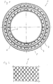
- the burner shown has a gas lance, not shown, which is surrounded by a recuperator 2.
- the latter consists of an annular air duct 3 and an annular exhaust duct 4, these being separated from one another by a tubular, heat-transmitting wall 5.
- a tubular mat 6 made of heat-resistant material is placed in each of the air duct 3 and the exhaust duct 4.
- the mat 6 consists of wire and has a structure, as can be seen in particular from FIG. 2.
- the mats 6 heat up and cause heat transfer by radiation. This increases with increasing temperature in the fourth power, compared to the linear increase in convective heat transfer. From 900 ° C upwards, the recuperator efficiency exceeds that of a finned heat exchanger.
- the mats 6 occupy approximately 5% of the free passage cross section of the air duct 3 or the exhaust duct 4. Due to this fact and their already low flow resistance, the pressure loss is comparatively low. Accordingly, a fan with a weaker dimension is used.
- the burner shown schematically consists of ceramic material.
- the invention is also applicable to Steel structures. Above all, it can be used in radiant heating pipes.
- a mat of carbon fibers or a structure made of wire coils pushed into one another can be used.
- the diameter of the carbon fibers or wire is approximately 1.2 mm.
- Heat-resistant plastic fibers can also be used.
Landscapes
- Physics & Mathematics (AREA)
- Engineering & Computer Science (AREA)
- Geometry (AREA)
- Thermal Sciences (AREA)
- Mechanical Engineering (AREA)
- General Engineering & Computer Science (AREA)
- Gas Burners (AREA)
- Air Supply (AREA)
- Heat-Exchange Devices With Radiators And Conduit Assemblies (AREA)
Applications Claiming Priority (2)
| Application Number | Priority Date | Filing Date | Title |
|---|---|---|---|
| DE1995118296 DE19518296A1 (de) | 1995-05-18 | 1995-05-18 | Rekuperatorbrenner |
| DE19518296 | 1995-05-18 |
Publications (2)
| Publication Number | Publication Date |
|---|---|
| EP0743500A2 true EP0743500A2 (fr) | 1996-11-20 |
| EP0743500A3 EP0743500A3 (fr) | 1997-11-26 |
Family
ID=7762273
Family Applications (1)
| Application Number | Title | Priority Date | Filing Date |
|---|---|---|---|
| EP96106942A Withdrawn EP0743500A3 (fr) | 1995-05-18 | 1996-05-03 | Brûleur à récupération |
Country Status (2)
| Country | Link |
|---|---|
| EP (1) | EP0743500A3 (fr) |
| DE (1) | DE19518296A1 (fr) |
Cited By (5)
| Publication number | Priority date | Publication date | Assignee | Title |
|---|---|---|---|---|
| EP0854345A1 (fr) * | 1997-01-21 | 1998-07-22 | VIESSMANN WERKE GmbH & CO. | Echangeur de chaleur |
| WO1998031976A1 (fr) * | 1997-01-21 | 1998-07-23 | Viessmann Werke Gmbh & Co. | Element echangeur de chaleur |
| DE19961284A1 (de) * | 1999-12-18 | 2001-07-12 | Bosch Gmbh Robert | Wärmeübertrager für Gasheizgeräte, insbesondere Brennwertgeräte |
| US8986001B2 (en) | 2009-12-16 | 2015-03-24 | Eclipse, Inc. | Burner with improved heat recuperator |
| EP3133344A1 (fr) * | 2015-08-20 | 2017-02-22 | AICHELIN Holding GmbH | Bruleur a recuperation comprenant un recuperateur ceramique et procede de fabrication |
Families Citing this family (1)
| Publication number | Priority date | Publication date | Assignee | Title |
|---|---|---|---|---|
| DE102011103106A1 (de) | 2011-05-25 | 2012-11-29 | Erbicol S.A. | Wärmeübertrager aus keramischem Material, insbesondere für Rekuperatorbrenner, und Verfahren zu dessen Herstellung |
Citations (1)
| Publication number | Priority date | Publication date | Assignee | Title |
|---|---|---|---|---|
| US4310303A (en) * | 1980-07-11 | 1982-01-12 | W. B. Combustion, Inc. | Plug-in recuperator and method |
Family Cites Families (17)
| Publication number | Priority date | Publication date | Assignee | Title |
|---|---|---|---|---|
| DE1069165B (de) * | 1959-11-19 | GEA-Luftkuhl'er-Gcsellschaft m.b. H., Bochum | Röhrenwarmeaustauscher für strömende Medien mit in den Rohren uim die Rohrlärtgsachse schraubenförmig gewundenen Bandblechen | |
| AT19301B (fr) * | 1903-09-15 | 1905-02-25 | Ignaz Wasniczek | |
| DE567819C (de) * | 1929-06-22 | 1933-01-10 | Aeg | Feuerung, insbesondere fuer Dampfkessel |
| DE975537C (de) * | 1948-04-28 | 1962-01-11 | Svenska Maskinverken Ab | Waermeaustauscher |
| FR1026192A (fr) * | 1949-09-19 | 1953-04-24 | Procédé de fabrication d'échangeurs calorifiques et les échangeurs calorifiques otenus conformément audit procédé | |
| DE1097461B (de) * | 1959-05-16 | 1961-01-19 | Daimler Benz Ag | Verfahren zum Reinigen von Regenerativwaermetauschern |
| FR1274532A (fr) * | 1960-09-06 | 1961-10-27 | Teikoku Sanso Kabushiki Kaisha | Nouveaux régénérateurs à garnissage et faisceau tubulaire bobiné |
| GB1056104A (en) * | 1962-07-20 | 1967-01-25 | Oestbo John D B | Improvements in or relating to heat-exchangers, pre-heaters and economizers |
| FR2453381A1 (fr) * | 1979-04-03 | 1980-10-31 | Ferodo Sa | Perfectionnements apportes aux echangeurs de chaleur et, notamment aux appareils de ce genre qui comportent des tubes |
| DE2948048C2 (de) * | 1979-11-29 | 1981-10-08 | Aichelin GmbH, 7015 Korntal | Industriebrenner |
| DE3017574C2 (de) * | 1980-05-08 | 1985-06-05 | Wieland-Werke Ag, 7900 Ulm | Abstandshalter für koaxiale Wärmeübertrager |
| US4432408A (en) * | 1982-07-19 | 1984-02-21 | The Dow Chemical Co. | Method and compressed vermicular expanded graphite apparatus for heat exchanging |
| GB2137332B (en) * | 1983-03-29 | 1986-06-18 | Arrenshaw | Improvements in or relating to heat exchangers |
| EP0250345B1 (fr) * | 1986-06-16 | 1991-03-13 | Le Carbone Lorraine | Contact thermique à fort coefficient de transfert et applications au refroidissement d'une structure soumise à un flux thermique intense |
| US5211219A (en) * | 1990-07-31 | 1993-05-18 | Daikin Industries, Ltd. | Air conditioner |
| DE4132236C1 (fr) * | 1991-09-27 | 1992-10-15 | Ws Waermeprozesstechnik Gmbh, 7253 Renningen, De | |
| US5390734A (en) * | 1993-05-28 | 1995-02-21 | Lytron Incorporated | Heat sink |
-
1995
- 1995-05-18 DE DE1995118296 patent/DE19518296A1/de not_active Withdrawn
-
1996
- 1996-05-03 EP EP96106942A patent/EP0743500A3/fr not_active Withdrawn
Patent Citations (1)
| Publication number | Priority date | Publication date | Assignee | Title |
|---|---|---|---|---|
| US4310303A (en) * | 1980-07-11 | 1982-01-12 | W. B. Combustion, Inc. | Plug-in recuperator and method |
Cited By (5)
| Publication number | Priority date | Publication date | Assignee | Title |
|---|---|---|---|---|
| EP0854345A1 (fr) * | 1997-01-21 | 1998-07-22 | VIESSMANN WERKE GmbH & CO. | Echangeur de chaleur |
| WO1998031976A1 (fr) * | 1997-01-21 | 1998-07-23 | Viessmann Werke Gmbh & Co. | Element echangeur de chaleur |
| DE19961284A1 (de) * | 1999-12-18 | 2001-07-12 | Bosch Gmbh Robert | Wärmeübertrager für Gasheizgeräte, insbesondere Brennwertgeräte |
| US8986001B2 (en) | 2009-12-16 | 2015-03-24 | Eclipse, Inc. | Burner with improved heat recuperator |
| EP3133344A1 (fr) * | 2015-08-20 | 2017-02-22 | AICHELIN Holding GmbH | Bruleur a recuperation comprenant un recuperateur ceramique et procede de fabrication |
Also Published As
| Publication number | Publication date |
|---|---|
| DE19518296A1 (de) | 1996-11-21 |
| EP0743500A3 (fr) | 1997-11-26 |
Similar Documents
| Publication | Publication Date | Title |
|---|---|---|
| WO1992020975A1 (fr) | Appareil de chauffage d'air | |
| EP0743500A2 (fr) | Brûleur à récupération | |
| DE1905148C3 (de) | Strahlungsbrenner | |
| EP0337923B1 (fr) | Chauffe-eau | |
| EP0065944A1 (fr) | Poêle en faîence | |
| DE3304868C2 (de) | Wassererhitzer | |
| DE2538824A1 (de) | Verfahren zur rationelleren ausnutzung der abwaerme von abfallverbrennungsanlagen und vorrichtung | |
| DE1910548U (de) | Waermeaustauscherhoehendes laengsbestroemtes element. | |
| WO2011117409A1 (fr) | Four pour le traitement thermique d'une pluralité d'objets | |
| EP0711954B1 (fr) | Cheminée d'air/fumée | |
| DE20308406U1 (de) | Ofen für Zahnersatz oder -teilersatz | |
| DE4032264C2 (de) | Vorrichtung zur Rückgewinnung von Wärme aus den Abgasen aus Feuerungsanlagen und Produktionsprozessen | |
| DE3117533A1 (de) | Rekuperator, vorzugsweise fuer industrieoefen | |
| DE2832442C2 (de) | Wärmeofen | |
| AT346539B (de) | Ofen mit eingebautem gasbrenner | |
| DE69001197T2 (de) | Kesselglied fuer niedertemperatur-heizkessel. | |
| AT397497B (de) | Setzstein aus feuerfestem material für gitterungen sowie gitterung | |
| DE2748576C3 (de) | Regenerativerhitzer | |
| DE3023238C2 (de) | Anordnung der Heizelemente in einem elektrisch beheizten Ofen mit stabförmigen Heizelementen | |
| DE2206536C2 (de) | Tunnelofen | |
| DE1526918C3 (fr) | ||
| AT389386B (de) | Wasserkessel | |
| DE1529197C (de) | Strahlungsbrenner | |
| DE4017971A1 (de) | Heizkoerper | |
| DE435095C (de) | Vorrichtung zur Erzielung eines moeglichst hohen Waermeueberganges und einer moeglichst gleichmaessigen Beheizung der einzelnen Rohre eines Rohrbuendels bei Wasserrohrkesseln |
Legal Events
| Date | Code | Title | Description |
|---|---|---|---|
| PUAI | Public reference made under article 153(3) epc to a published international application that has entered the european phase |
Free format text: ORIGINAL CODE: 0009012 |
|
| AK | Designated contracting states |
Kind code of ref document: A2 Designated state(s): AT BE CH DE FR GB IT LI LU |
|
| PUAL | Search report despatched |
Free format text: ORIGINAL CODE: 0009013 |
|
| AK | Designated contracting states |
Kind code of ref document: A3 Designated state(s): AT BE CH DE FR GB IT LI LU |
|
| 17P | Request for examination filed |
Effective date: 19971209 |
|
| ET | Fr: translation filed | ||
| RAP1 | Party data changed (applicant data changed or rights of an application transferred) |
Owner name: L B E FEUERUNGSTECHNIK GMBH |
|
| 17Q | First examination report despatched |
Effective date: 20000412 |
|
| STAA | Information on the status of an ep patent application or granted ep patent |
Free format text: STATUS: THE APPLICATION IS DEEMED TO BE WITHDRAWN |
|
| 18D | Application deemed to be withdrawn |
Effective date: 20000823 |