EP0741669B1 - Verfahren und vorrichtung zur thermischen trennung von flüssigkeitskomponenten - Google Patents
Verfahren und vorrichtung zur thermischen trennung von flüssigkeitskomponenten Download PDFInfo
- Publication number
- EP0741669B1 EP0741669B1 EP95909620A EP95909620A EP0741669B1 EP 0741669 B1 EP0741669 B1 EP 0741669B1 EP 95909620 A EP95909620 A EP 95909620A EP 95909620 A EP95909620 A EP 95909620A EP 0741669 B1 EP0741669 B1 EP 0741669B1
- Authority
- EP
- European Patent Office
- Prior art keywords
- carrier gas
- liquid
- component
- condensate
- evaporation
- Prior art date
- Legal status (The legal status is an assumption and is not a legal conclusion. Google has not performed a legal analysis and makes no representation as to the accuracy of the status listed.)
- Expired - Lifetime
Links
Images

Classifications
-
- B—PERFORMING OPERATIONS; TRANSPORTING
- B01—PHYSICAL OR CHEMICAL PROCESSES OR APPARATUS IN GENERAL
- B01D—SEPARATION
- B01D3/00—Distillation or related exchange processes in which liquids are contacted with gaseous media, e.g. stripping
- B01D3/34—Distillation or related exchange processes in which liquids are contacted with gaseous media, e.g. stripping with one or more auxiliary substances
- B01D3/343—Distillation or related exchange processes in which liquids are contacted with gaseous media, e.g. stripping with one or more auxiliary substances the substance being a gas
- B01D3/346—Distillation or related exchange processes in which liquids are contacted with gaseous media, e.g. stripping with one or more auxiliary substances the substance being a gas the gas being used for removing vapours, e.g. transport gas
-
- B—PERFORMING OPERATIONS; TRANSPORTING
- B01—PHYSICAL OR CHEMICAL PROCESSES OR APPARATUS IN GENERAL
- B01D—SEPARATION
- B01D5/00—Condensation of vapours; Recovering volatile solvents by condensation
- B01D5/0003—Condensation of vapours; Recovering volatile solvents by condensation by using heat-exchange surfaces for indirect contact between gases or vapours and the cooling medium
- B01D5/0015—Plates
-
- B—PERFORMING OPERATIONS; TRANSPORTING
- B01—PHYSICAL OR CHEMICAL PROCESSES OR APPARATUS IN GENERAL
- B01D—SEPARATION
- B01D5/00—Condensation of vapours; Recovering volatile solvents by condensation
- B01D5/0057—Condensation of vapours; Recovering volatile solvents by condensation in combination with other processes
- B01D5/006—Condensation of vapours; Recovering volatile solvents by condensation in combination with other processes with evaporation or distillation
- B01D5/0066—Dome shaped condensation
-
- C—CHEMISTRY; METALLURGY
- C02—TREATMENT OF WATER, WASTE WATER, SEWAGE, OR SLUDGE
- C02F—TREATMENT OF WATER, WASTE WATER, SEWAGE, OR SLUDGE
- C02F1/00—Treatment of water, waste water, or sewage
- C02F1/02—Treatment of water, waste water, or sewage by heating
- C02F1/04—Treatment of water, waste water, or sewage by heating by distillation or evaporation
- C02F1/14—Treatment of water, waste water, or sewage by heating by distillation or evaporation using solar energy
-
- Y—GENERAL TAGGING OF NEW TECHNOLOGICAL DEVELOPMENTS; GENERAL TAGGING OF CROSS-SECTIONAL TECHNOLOGIES SPANNING OVER SEVERAL SECTIONS OF THE IPC; TECHNICAL SUBJECTS COVERED BY FORMER USPC CROSS-REFERENCE ART COLLECTIONS [XRACs] AND DIGESTS
- Y02—TECHNOLOGIES OR APPLICATIONS FOR MITIGATION OR ADAPTATION AGAINST CLIMATE CHANGE
- Y02A—TECHNOLOGIES FOR ADAPTATION TO CLIMATE CHANGE
- Y02A20/00—Water conservation; Efficient water supply; Efficient water use
- Y02A20/124—Water desalination
- Y02A20/138—Water desalination using renewable energy
- Y02A20/142—Solar thermal; Photovoltaics
-
- Y—GENERAL TAGGING OF NEW TECHNOLOGICAL DEVELOPMENTS; GENERAL TAGGING OF CROSS-SECTIONAL TECHNOLOGIES SPANNING OVER SEVERAL SECTIONS OF THE IPC; TECHNICAL SUBJECTS COVERED BY FORMER USPC CROSS-REFERENCE ART COLLECTIONS [XRACs] AND DIGESTS
- Y02—TECHNOLOGIES OR APPLICATIONS FOR MITIGATION OR ADAPTATION AGAINST CLIMATE CHANGE
- Y02A—TECHNOLOGIES FOR ADAPTATION TO CLIMATE CHANGE
- Y02A20/00—Water conservation; Efficient water supply; Efficient water use
- Y02A20/20—Controlling water pollution; Waste water treatment
- Y02A20/208—Off-grid powered water treatment
- Y02A20/212—Solar-powered wastewater sewage treatment, e.g. spray evaporation
Definitions
- the invention relates to a method for thermal separation of different volatile Components of a liquid by heating the Liquid until the more volatile evaporates Component, by deducting the evaporation Component steam and its subsequent Condensation to form component condensate.
- the invention also relates to a device for Execution of the procedure.
- US-A-4 363 703 discloses a method and an apparatus for desalting water by means of solar energy, wherein the generated steam is removed by means of a carrier gas and then cooled.
- the object of the invention is a method for thermal Separation of volatile components from liquids to create a simple with a small footprint apparatus design allowed.
- the subset of the liquid is preferred on a the liquid evaporates on the absorbent surface, Claim 2.
- Surfaces for the liquid are absorbent, transport the liquid to be separated automatically. They also offer a surface structure which favors the evaporation of the liquid and the decomposable per surface unit Liquid volume increased. It can be done in a simple manner by adjusting the surface temperature self-regulating balance between generated Component vapor and amount of liquid sucked to the surface adjust what is constant because of this permanent moisture levels on the surface Process management facilitated.
- A is preferred for the absorbent surface Surface with fibrous structure used, Claim 3.
- textile material such as absorbent paper or cardboard, sintered materials such as Ceramic plates or porous plastics are suitable.
- a suitable device for performing the method is in claim 5 and the following Claims 6 to 14 specified.
- the device is for the evaporation of component vapor formed with a Fume hood equipped in a condensation chamber flows into which the component vapor condenses and Condensate is obtained.
- the steam vent leads into Condensate storage so that the component vapor is in contact condensed with component condensate and cooling surfaces, which is the liquid from which a subset evaporates is used as a coolant.
- To absorb the part of the liquid to be evaporated is a heatable using solar energy Surface provided in one for transportation of the component vapor from the evaporation space through which the carrier gas flows is arranged.
- a surface that is absorbent for the liquid is preferred used.
- an absorbent material is before all used a fibrous structured material.
- wettable porous materials such as sintered ceramic or porous plastic plates. The Material is especially for heating by solar energy suitable.
- the evaporation space expediently has several adjacent and evaporation surfaces arranged parallel to each other on, between which there are flow spaces for the the carrier gas which removes the component vapor formed are located.
- the flow can be supported by fans will.
- Part of the liquid used to cool the cooling surfaces flows through the condensation chamber, then serves for pre-cooling the carrier gas before it Entry into the condensate chamber.
- the inventive method and the device experience an important application in the production of drinking water from salt water, claim 13.
- drinking water can be obtained from sea water.
- the drawing shows a schematic representation of a Device for desalination of salt water and production of fresh water.
- the salt water becomes fresh water thermally as a more volatile component severed. To heat the device Solar energy used.
- the exemplary embodiment can be transferred analogously to thermal separation process for other liquids that have different volatile components.
- the Process can be used, for example, for cleaning liquids, in particular water purification or for the enrichment of a more volatile component in the liquid, however also - with complete evaporation of the evaporable Liquid component - for the production of solid layers, especially of salt layers on material webs, be used.
- an evaporation chamber 1 for the liquid for evaporation its more volatile component and Training of component vapor provided and below of the evaporation chamber a condensate chamber 2 for precipitation the condensate vapor and for storing the Component condensate in a condensate storage 3 arranged.
- the evaporation chamber 1 is for heat rays transparent glass or synthetic glass as transparent cover 4 completed and is heated by solar energy.
- Evaporator plates 5, which form the surfaces 6 on which the Evaporation of subsets of the liquid takes place are so in the evaporation chamber 1 used that they are heated by solar energy.
- the Evaporation plates 5 are located within one of the Carrier gas 7 flow formed.
- Air is used as the carrier gas 7 in the exemplary embodiment.
- Fig. 1 are flow lines for the carrier gas 7 in the evaporation chamber 1 and in the Condensate chamber 2 shown.
- the carrier gas flows via a carrier gas inlet 8 into a preheating chamber 9 serving carrier gas channel.
- the preheating chamber 9 is in the same way as the evaporator plate 5 of Solar energy warms up, with the resulting heat on the carrier gas flowing through the preheating chamber becomes.
- This flows through in the evaporation chamber 1 hot carrier gas gaps 10 between the Distance adjacent to each other and arranged plane-parallel Evaporator plates 5.
- the carrier gas takes the formed component vapor and is on a End of the evaporation room 1 connected fume hood 11 introduced into the condensate chamber 2.
- the carrier gas 7 flows between cooling surfaces 12 through, which are arranged such that for the moist carrier gas is a meandering flow path is formed, and passes through a carrier gas vent 13 to the carrier gas outlet 14.
- the carrier gas outlet 13 there is a suction fan in the embodiment 15, the carrier gas transport from the carrier gas inlet 8th effected up to the carrier gas outlet 14.
- a control valve in the carrier gas discharge 13 16 used, only schematically in Figure 1 is specified.
- the evaporator plates 5 wetted from an inlet 17 for salt water.
- the inflow 17 is above the evaporation plates 5 as Sprinkler system trained and points for each of the evaporation plates 5 a liquid distributor 18.
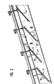
- the evaporation plates 5 are in the embodiment highly absorbent for solar energy. You assign one wavy surface with a smooth structure made of a material with an absorbent surface, in the exemplary embodiment they are with plastic sponge 19 occupied, see Fig. 2. It becomes a for evaporation large evaporation surface available per unit area provided that can be optimally heated by solar energy is.
- a liquid drain pan 20 arranged in the non-evaporated Liquid, in the exemplary embodiment enriched in salt Brine, collected and into one in Figure 1 Spout 21 shown can run.
- FIG. 2 shows a partial section of the evaporation space 1 the water desalination plant shown in Figure 1.
- the evaporation plates 5 and the plastic sponge 19 are heated by solar energy, with the Evaporation of the more volatile component of the Liquid-serving surface 6 of the plastic sponge is directly exposed to sunlight.
- the evaporation plates 5 are for radiation absorption within of the evaporation chamber 1 in one set in this way Angle 22 arranged that during sun exposure optimal heating of the effective evaporation surfaces 6 results.
- the evaporation plates 5 are attached to brackets 23 in the embodiment, through which the evaporation plates 5 to change the Irradiation angle 22 are rotatable.
- the more volatile component of the liquid evaporates on the surface 6 with the plastic sponge 19 equipped evaporator plates 5.
- the component vapor formed in the gaps 10 between the plane-parallel evaporator plates is taken up by the air as carrier gas 7 and with the carrier gas from the evaporation chamber 1 the steam vent 11 transported into the condensate chamber 2.
- the component steam with the cooling surfaces 12 and that formed on the cooling surfaces 12 Component condensate and the condensate storage 3 draining condensate in contact and condensed due to the low temperature of the condensate and the Cooling surfaces whose temperature is below the condensation temperature of the component vapor.
- Coolant for the cooling surfaces 12 is in the embodiment the salt water from a salt water pump 24 is sucked in and via a pipeline 25 to Condensate chamber 2 is guided. To a corresponding To achieve cooling, cool sea water is made deeper ocean layers. The sea water first flows into a distributor 26 and then through the cooling surfaces 12 of the condensate chamber 2.
- the salt water flows in from the cooling surfaces 12 Collector tube 27 and is in a drain line 28th dissipated.
- Part of the outflowing salt water serves for pre-cooling the flowing out of the evaporation chamber 1 Carrier gas 7.
- a precooler 31 performed inside the fume hood 11 is arranged. Introduces from precooler 31 Coolant drain 32 from most of the salt water, this part of the sea water flows back into the sea, as far as its residual heat by appropriate setting of a three-way valve used in the coolant drain 33 should not be used further as another variant of the method according to the invention will be explained.
- the residual heat from the Pre-cooler 31 flowing sea water still further exploited, in the embodiment to set the Temperature of recycle carrier gas.
- the sea water becomes a via a drain line 37
- Out heat exchanger 38 which flows through carrier gas with the appropriate adjustment of the control flap 16 from the suction fan 15 from the carrier gas vent 13 returned in a return line 39 to the preheating chamber 9 becomes.
- the return line 39 opens at the carrier gas inlet 8 into the preheating chamber 9.
- the carrier gas inlet 8 is closed with a Klapppe 40, so that Carrier gas circulates in a closed circuit.
- the Flap 40 and the control flap 16 in the carrier gas vent 13 can be controlled coordinated.
- the Suction fan 15 in the carrier gas vent 13 ensures that thus generated carrier gas cycle.
- In the embodiment becomes the air used as the carrier gas in the heat exchanger 38 to an air temperature of set at least 25 ° C or higher.
- the air used as the carrier gas is heated at an air flow rate of 0.125 m 3 / sec in the preheating chamber 9 by solar energy of 25 ° C. inlet temperature at the carrier gas inlet 8 up to 64 ° C. before entering the evaporation chamber.
- An annual average solar radiation of 1 KW / m 2 is assumed, 5m 2 solar collector area is therefore made available for air heating in the preheating chamber.
- the heat content of the air achieved in this design at 64 ° C is used for water evaporation.
- the flow cross section in the preheating chamber 9 is 0.125 m 2 , so that there is a flow velocity for the air as carrier gas of 1 m / sec.
- the heated air is enriched with component vapor at the beginning of its cycle as carrier gas, in the exemplary embodiment water vapor up to 21% relative air humidity.
- water vapor up to 21% relative air humidity.
- the relative humidity of the air emerging from the evaporation space 1 increases to 47%.
- the sea water is heated to evaporate in the salt water preheater 36 up to 50 ° C and higher. It is applied at this temperature to the evaporation plates 5, so that only the evaporation energy (evaporation energy) necessary for the evaporation of the sea water at 50 ° C. has to be supplied from the evaporation plates.
- the evaporation plates have a sun-exposed active surface of 1.5 m 2 , with an annual solar radiation of 1 KW / m 2 , 1.5 KW are available for water evaporation.
- approx. 10 g / sec water can be transported at 100% relative air humidity.
- 2.1 g / sec of water are initially transported with the air stream as the carrier gas. That is 21% relative humidity.
- the air emerging from the condensate chamber 2 at a temperature of 25 ° C has a relative humidity of 100% or a water content of approx. 20.8 g / m 3 of air. In the exemplary embodiment, this is approximately 2.6 g / sec of water.
- the system that is running thus runs in the vapor exhaust 11 between the evaporation chamber 1 and the condensate chamber 2 with a relative air humidity of 47.3%.
- the temperatures and moisture contents can be maintained with only slight deviations with circulated air.
- the carrier gas humidified in this way in the evaporation chamber 1 is dried again in the condensate chamber 2 on the cooling surfaces 12 in contact with component condensate which has already formed.
- 10 cooling surfaces each with a surface area of approximately 100 ⁇ 25 cm 2, are used in the condensate chamber 2 .
- the cooling surfaces 12 are arranged in the condensate chamber 2 such that the humidified carrier gas 7 flows through the condensate chamber in a meandering flow path.
- the temperature of the cooling surfaces 12 and thus the temperature of the condensate with which the humidified carrier gas comes into contact is a maximum of 25 ° C. in the exemplary embodiment.
- the air flows out again as a "dry" carrier gas from the condensate chamber 2 at approximately 25 ° C. and can be returned in a circuit to the preheating chamber 9 via the return line 39.
- the condensate chamber 2 are in the embodiment approx. 8 l / h desalinated water, especially drinking water obtained as a component condensate.
- the water flows on the cooling surfaces 12 to the bottom 41 of the condensate chamber 2 and is led from there to the condensate storage 3.
Description
- Fig. 1:
- Vorrichtung zur Erzeugung von Frischwasser aus Salzwasser (Längsschnitt);
- Fig. 2:
- Teilschnitt des Verdunstungsraums der Vorrichtung nach Fig. 1
| Wärmemenge Q: | |
| - Überschußwärme bei Lufttemp. 64°C (Überschußwärme > 50°C Lufttemp.) = | 1,5 KW |
| - Wärme aus bestrahlter Verdunstungsfläche 1,5 m2 bei 1 kW/m2 Solarstrahlung m2 bei | 1,5 KW |
| - Wärmerückgewinn im Vorkühler 31 | 1,0 KW |
| - Wärmerückgewinn im Salzwasservorwärmer 36 | 1,0 KW |
| Wärmenge Q insgesamt = | 5,0 KW |
Claims (14)
- Verfahren zur thermischen Trennung von unterschiedlich flüchtigen Komponenten einer Flüssigkeit durch Aufheizung der Flüssigkeit bis zur Verdunstung der leichter flüchtigen Komponente,wobei bei der Verdunstung gebildeter Komponentendampf mittels eines Trägergases abgeführt wird, das vor Aufnahme des Komponentendampfes durch Aufheizen des Trägergases mittels Solarenergie auf den thermischen Zustand des Komponentendampfes gebracht worden ist,wobei zur anschließenden Kondensation und Ausbildung von Komponentenkondensat der im Trägergas enthaltene Komponentendampf in Kontakt mit Komponentenkondensat und Kühlflächen niederschlagen wird, die von der Flüssigkeit gekühlt werden,wobei nach Kühlung der Kühlflächen eine Teilmenge der Flüssigkeit auf einer die Teilmenge aufnehmenden, zur Verdunstung der leichter flüchtigen Flüssigkeitskomponente unter Ausnutzung von Solarenergie erwärmten Oberfläche verteilt wird, undwobei das Trägergas im Kreislauf geführt wird.
- Verfahren nach Anspruch 1,
dadurch gekennzeichnet,
daß die Teilmenge der Flüssigkeit auf einer die Flüssigkeit aufsaugenden Oberfläche verdunstet wird. - Verfahren nach Anspruch 2,
dadurch gekennzeichnet,
daß die Oberfläche eine faserartige Struktur aufweist. - Verfahren nach einem der Ansprüche 1, 2 oder 3,
dadurch gekennzeichnet,
daß das Trägergas vor Zutritt zum Verdunstungsraum auf Komponentendampftemperatur erhitzt wird. - Vorrichtung zur thermischen Abtrennung von unterschiedlich flüchtigen Komponenten einer Flüssigkeit durch Aufheizen der Flüssigkeit bis zum Verdunsten der leichter flüchtigen Komponente, mit einem Dampfabzug (11) für beim Verdunsten gebildeten Komponentendampf und mit einer nachgeschalteten Kondensatkammer (2) zum Speichern von aus dem Komponentendampf gewonnenen Komponentenkondensat, wobei zur Gewinnung des Komponentenkondensats in der Kondensatkammer (2) Kühlflächen (12) angeordnet sind, die von der Flüssigkeit gekühlt werden, von der eine Teilmenge anschließend verdunstet wird, und wobei zur Aufnahme der Teilmenge der Flüssigkeit eine unter Ausnutzung von Solarenergie erwärmbare Oberfläche (6) vorgesehen ist, die zum Komponentendampf-Transport in einem von Trägergas (7) durchströmten Verdunstungsraum (1) angeordnet ist, wobei dem Verdunstungsraum (1) eine vom Trägergas durchströmte, von Solarenergie erhitzte Vorwärmkammer (9) für das Trägergas vorgeschaltet ist, wobei der Dampfabzug (11) in der Kondensatkammer (2) derart mündet, daß der im Trägergas enthaltende Komponentendampf mit den Kühlflächen (12) und mit auf den Kühlflächen gebildeten Komponentenkondensat kontaktiert wird, und wobei für das Trägergas eine am Trägergasabzug (13) am Ausgang der Kondensatkammer (2) angeschlossene Rückführleitung (39) zur Rückführung des Trägergases zum Trägergaseinlaß (8) an der Vorwärmkammer (9) vorgesehen ist.
- Vorrichtung nach Anspruch 5,
dadurch gekennzeichnet,
daß eine für die Flüssigkeit saugfähige Oberfläche (6) eingesetzt ist. - Vorrichtung nach Anspruch 6,
dadurch gekennzeichnet,
daß die Oberfläche (6) eine faserartige Struktur aufweist. - Vorrichtung nach einem der vorhergehenden Ansprüche 5 bis 7,
dadurch gekennzeichnet,
daß die Oberfläche (6) von saugfähigem und/oder eine faserartige Struktur aufweisenden Material bedeckt ist. - Vorrichtung nach Anspruch 8,
dadurch gekennzeichnet,
daß das Material mittels Solarenergie aufheizbar ist. - Vorrichtung nach einem der vorhergehenden Ansprüche 5 bis 9,
dadurch gekennzeichnet,
daß die Oberfläche (6) von mehreren benachbart und parallel zueinander angeordneten Verdunstungsflächen gebildet ist, die zwischen sich Strömungsräume (10) für das Trägergas (7) aufweisen. - Vorrichtung nach einem der Ansprüche 5 bis 10,
dadurch gekennzeichnet,
daß ein Teil der Flüssigkeit nach Durchströmen der Kühlflächen (12) zur Vorkühlung des Trägergases (7) vor dessen Eintritt in die Kondensatkammer (2) dient. - Vorrichtung nach einem der vorhergehenden Ansprüche 5 bis 11
dadurch gekennzeichnet
daß in der Rückführleitung (39) ein von einem Teil der abgeführten Flüssigkeit durchströmter Wärmetauscher (38) eingesetzt ist. - Verwendung des Verfahrens nach einem der Ansprüche 1 bis 4 und der Vorrichtung nach einem der Ansprüche 5 bis 12 zur Gewinnung entsalzten Wassers.
- Verwendung nach Anspruch 13,
dadurch gekennzeichnet
daß aus Salzwasser Trinkwasser gewonnen wird.
Applications Claiming Priority (3)
| Application Number | Priority Date | Filing Date | Title |
|---|---|---|---|
| DE4403592A DE4403592C1 (de) | 1994-02-05 | 1994-02-05 | Verfahren und Vorrichtung zur thermischen Trennung von Flüssigkeitskomponenten |
| DE4403592 | 1994-02-05 | ||
| PCT/DE1995/000141 WO1995021130A1 (de) | 1994-02-05 | 1995-02-03 | Verfahren und vorrichtung zur thermischen trennung von flüssigkeitskomponenten |
Publications (2)
| Publication Number | Publication Date |
|---|---|
| EP0741669A1 EP0741669A1 (de) | 1996-11-13 |
| EP0741669B1 true EP0741669B1 (de) | 1998-11-25 |
Family
ID=6509552
Family Applications (1)
| Application Number | Title | Priority Date | Filing Date |
|---|---|---|---|
| EP95909620A Expired - Lifetime EP0741669B1 (de) | 1994-02-05 | 1995-02-03 | Verfahren und vorrichtung zur thermischen trennung von flüssigkeitskomponenten |
Country Status (5)
| Country | Link |
|---|---|
| EP (1) | EP0741669B1 (de) |
| DE (1) | DE4403592C1 (de) |
| ES (1) | ES2125600T3 (de) |
| GR (1) | GR3029459T3 (de) |
| WO (1) | WO1995021130A1 (de) |
Families Citing this family (7)
| Publication number | Priority date | Publication date | Assignee | Title |
|---|---|---|---|---|
| TW401647B (en) * | 1996-06-19 | 2000-08-11 | Ebara Corp | Desalting apparatus and method for operating such process |
| DE10018096C1 (de) * | 2000-04-12 | 2002-01-31 | Clemens & Co Gmbh | Vorrichtung zur Rückgewinnung von Aromastoffen aus Gärgasen |
| CN1275866C (zh) * | 2004-08-27 | 2006-09-20 | 程显超 | 太阳能海水淡化装置 |
| AT507297B1 (de) * | 2008-12-03 | 2010-04-15 | Fh Ooe Forschungs & Entwicklun | Solare kondensationsanlage mit kaskadenverdunstung |
| WO2014063713A1 (en) * | 2012-10-23 | 2014-05-01 | Bakr Hesham Ahmed Awadalla | The solar method for water desalination |
| DE102013111352A1 (de) | 2013-10-15 | 2015-04-16 | WätaS Wärmetauscher Sachsen GmbH | Reinigungsverfahren und Reinigungsanlage für mit Begleitstoffen belastetes Wasser |
| IT202000008194A1 (it) * | 2020-04-17 | 2021-10-17 | Alessandro Luigi Maria Vergani | Apparecchiatura di evaporazione di liquidi |
Family Cites Families (5)
| Publication number | Priority date | Publication date | Assignee | Title |
|---|---|---|---|---|
| US4487659A (en) * | 1979-06-04 | 1984-12-11 | North American Utility Construction Corp. | Solar distillation apparatus |
| US4318781A (en) * | 1980-01-11 | 1982-03-09 | Tomimaru Iida | Desalinazation apparatus |
| US4363703A (en) * | 1980-11-06 | 1982-12-14 | Institute Of Gas Technology | Thermal gradient humidification-dehumidification desalination system |
| SE8401503L (sv) * | 1984-03-15 | 1985-09-16 | Sven Runo Vilhelm Gebelius | Sett och anordning for avsaltning och/eller rening av vatten |
| DE3618279A1 (de) * | 1986-03-27 | 1987-10-01 | Solaqua Rosendahl Meerwasseren | Verfahren zur erwaermung und verdampfung bzw. verdunstung einer fluessigkeit mittels sonnenenergie, vorrichtung zur durchfuehrung des verfahrens und anwendung des verfahrens bzw. der vorrichtung |
-
1994
- 1994-02-05 DE DE4403592A patent/DE4403592C1/de not_active Expired - Fee Related
-
1995
- 1995-02-03 EP EP95909620A patent/EP0741669B1/de not_active Expired - Lifetime
- 1995-02-03 WO PCT/DE1995/000141 patent/WO1995021130A1/de active IP Right Grant
- 1995-02-03 ES ES95909620T patent/ES2125600T3/es not_active Expired - Lifetime
-
1999
- 1999-02-19 GR GR990400544T patent/GR3029459T3/el unknown
Also Published As
| Publication number | Publication date |
|---|---|
| WO1995021130A1 (de) | 1995-08-10 |
| GR3029459T3 (en) | 1999-05-28 |
| DE4403592C1 (de) | 1995-06-22 |
| ES2125600T3 (es) | 1999-03-01 |
| EP0741669A1 (de) | 1996-11-13 |
Similar Documents
| Publication | Publication Date | Title |
|---|---|---|
| DE3112063C2 (de) | ||
| DE3049838C2 (de) | ||
| DE2459935A1 (de) | Anlage zur reinigung von fluessigkeit, insbesondere zur erzeugung von frischwasser aus meerwasser | |
| DE3152371T1 (de) | Verfahren und vorrichtung fuer die behandlung von gas, insbesondere luft | |
| DE2534621A1 (de) | Verfahren zum entsalzen von meerwasser oder dergleichen zur gewinnung von suesswasser und vorrichtung zur durchfuehrung des verfahrens | |
| EP0266684B1 (de) | Verfahren zum Regenerieren einer mit Feuchtigkeit beladenen Trocknungspatrone sowie Trockner mit einer Regeneriervorrichtung zur Durchführung eines solchen Verfahrens | |
| DD283941A5 (de) | Verfahren fuer die evaporative konzentration einer fluessigkeit | |
| DE1792662C3 (de) | Mehrstufige Destillationsvorichtung | |
| EP0741669B1 (de) | Verfahren und vorrichtung zur thermischen trennung von flüssigkeitskomponenten | |
| DE4340745C2 (de) | Verfahren und Vorrichtung zur Gewinnung von Brauchwasser aus verunreinigten Wässern | |
| DE102013111352A1 (de) | Reinigungsverfahren und Reinigungsanlage für mit Begleitstoffen belastetes Wasser | |
| DE2902369A1 (de) | Einrichtung zum entfeuchten und temperieren der in einer trocknungskammer fuer die holztrocknung bewegten kammerluft | |
| AT507297B1 (de) | Solare kondensationsanlage mit kaskadenverdunstung | |
| EP2952824A1 (de) | Vorrichtung und verfahren zur solaren destillation | |
| EP1519118A1 (de) | Verfahren und Vorrichtung zur Befeuchtung der Luft in raumlufttechnischen Anlagen von Gebauden und Fahrzeugen | |
| WO2004067451A1 (de) | Vorrichtung zum teinigen von wasser | |
| DE19929212C2 (de) | Verfahren und Vorrichtung zum Destillieren eines flüssigen Stoffs aus einer Lösung | |
| DE102013224351B4 (de) | Vorrichtung zur Erzeugung von Brauchwasser | |
| DE3828882A1 (de) | Vorrichtung zur speisewasseraufbereitung fuer ein kraftwerk | |
| DD283943A5 (de) | Prozess und anordnung zur konditionierung von luft | |
| DE3629398A1 (de) | Verfahren und vorrichtung zur entfeuchtung gasfoermiger medien | |
| DE10215079B4 (de) | Verfahren zum Destillieren oder Entsalzen von Flüssigkeiten | |
| DE1451133C2 (de) | Mischkondensator | |
| EP0752567A1 (de) | Verfahren zur Trocknung der Feststoffisolationen eines elektrischen Gerätes und Vorrichtung zur Durchführung dieses Verfahrens | |
| EP1475136A1 (de) | Vorrichtung zur Destillation |
Legal Events
| Date | Code | Title | Description |
|---|---|---|---|
| PUAI | Public reference made under article 153(3) epc to a published international application that has entered the european phase |
Free format text: ORIGINAL CODE: 0009012 |
|
| 17P | Request for examination filed |
Effective date: 19960725 |
|
| AK | Designated contracting states |
Kind code of ref document: A1 Designated state(s): ES GR PT |
|
| GRAG | Despatch of communication of intention to grant |
Free format text: ORIGINAL CODE: EPIDOS AGRA |
|
| 17Q | First examination report despatched |
Effective date: 19980202 |
|
| GRAG | Despatch of communication of intention to grant |
Free format text: ORIGINAL CODE: EPIDOS AGRA |
|
| GRAH | Despatch of communication of intention to grant a patent |
Free format text: ORIGINAL CODE: EPIDOS IGRA |
|
| GRAH | Despatch of communication of intention to grant a patent |
Free format text: ORIGINAL CODE: EPIDOS IGRA |
|
| GRAA | (expected) grant |
Free format text: ORIGINAL CODE: 0009210 |
|
| AK | Designated contracting states |
Kind code of ref document: B1 Designated state(s): ES GR PT |
|
| REG | Reference to a national code |
Ref country code: ES Ref legal event code: FG2A Ref document number: 2125600 Country of ref document: ES Kind code of ref document: T3 |
|
| REG | Reference to a national code |
Ref country code: PT Ref legal event code: SC4A Free format text: AVAILABILITY OF NATIONAL TRANSLATION Effective date: 19981222 |
|
| PLBE | No opposition filed within time limit |
Free format text: ORIGINAL CODE: 0009261 |
|
| STAA | Information on the status of an ep patent application or granted ep patent |
Free format text: STATUS: NO OPPOSITION FILED WITHIN TIME LIMIT |
|
| 26N | No opposition filed | ||
| PGFP | Annual fee paid to national office [announced via postgrant information from national office to epo] |
Ref country code: GR Payment date: 20000119 Year of fee payment: 6 |
|
| PGFP | Annual fee paid to national office [announced via postgrant information from national office to epo] |
Ref country code: PT Payment date: 20000124 Year of fee payment: 6 |
|
| PGFP | Annual fee paid to national office [announced via postgrant information from national office to epo] |
Ref country code: ES Payment date: 20000222 Year of fee payment: 6 |
|
| PG25 | Lapsed in a contracting state [announced via postgrant information from national office to epo] |
Ref country code: ES Free format text: LAPSE BECAUSE OF NON-PAYMENT OF DUE FEES Effective date: 20010205 |
|
| PG25 | Lapsed in a contracting state [announced via postgrant information from national office to epo] |
Ref country code: PT Free format text: LAPSE BECAUSE OF NON-PAYMENT OF DUE FEES Effective date: 20010831 Ref country code: GR Free format text: LAPSE BECAUSE OF NON-PAYMENT OF DUE FEES Effective date: 20010831 |
|
| REG | Reference to a national code |
Ref country code: PT Ref legal event code: MM4A Free format text: LAPSE DUE TO NON-PAYMENT OF FEES Effective date: 20010831 |
|
| REG | Reference to a national code |
Ref country code: ES Ref legal event code: FD2A Effective date: 20021016 |