EP0741206A1 - Überlaufklappenwehr - Google Patents
Überlaufklappenwehr Download PDFInfo
- Publication number
- EP0741206A1 EP0741206A1 EP96400709A EP96400709A EP0741206A1 EP 0741206 A1 EP0741206 A1 EP 0741206A1 EP 96400709 A EP96400709 A EP 96400709A EP 96400709 A EP96400709 A EP 96400709A EP 0741206 A1 EP0741206 A1 EP 0741206A1
- Authority
- EP
- European Patent Office
- Prior art keywords
- panel
- stiffening element
- door
- ground
- articulated
- Prior art date
- Legal status (The legal status is an assumption and is not a legal conclusion. Google has not performed a legal analysis and makes no representation as to the accuracy of the status listed.)
- Granted
Links
- XLYOFNOQVPJJNP-UHFFFAOYSA-N water Substances O XLYOFNOQVPJJNP-UHFFFAOYSA-N 0.000 claims abstract description 23
- 238000011144 upstream manufacturing Methods 0.000 claims description 11
- 230000004888 barrier function Effects 0.000 claims description 9
- 238000005452 bending Methods 0.000 claims description 5
- 230000003014 reinforcing effect Effects 0.000 abstract description 3
- 239000002184 metal Substances 0.000 description 6
- 230000002787 reinforcement Effects 0.000 description 6
- 230000001154 acute effect Effects 0.000 description 3
- 238000003466 welding Methods 0.000 description 3
- 230000014759 maintenance of location Effects 0.000 description 2
- 230000000284 resting effect Effects 0.000 description 2
- 230000000712 assembly Effects 0.000 description 1
- 238000000429 assembly Methods 0.000 description 1
- 230000000694 effects Effects 0.000 description 1
- 238000004519 manufacturing process Methods 0.000 description 1
- 239000000463 material Substances 0.000 description 1
- 238000005086 pumping Methods 0.000 description 1
- 238000012876 topography Methods 0.000 description 1
Images


Classifications
-
- E—FIXED CONSTRUCTIONS
- E02—HYDRAULIC ENGINEERING; FOUNDATIONS; SOIL SHIFTING
- E02B—HYDRAULIC ENGINEERING
- E02B7/00—Barrages or weirs; Layout, construction, methods of, or devices for, making same
- E02B7/20—Movable barrages; Lock or dry-dock gates
- E02B7/40—Swinging or turning gates
- E02B7/48—Roof or double shutter gates
-
- E—FIXED CONSTRUCTIONS
- E02—HYDRAULIC ENGINEERING; FOUNDATIONS; SOIL SHIFTING
- E02B—HYDRAULIC ENGINEERING
- E02B7/00—Barrages or weirs; Layout, construction, methods of, or devices for, making same
- E02B7/20—Movable barrages; Lock or dry-dock gates
- E02B7/40—Swinging or turning gates
- E02B7/44—Hinged-leaf gates
Definitions
- the present invention relates to an overflow barrier door, of the type comprising at least one tilting flap panel forming a rectangular shape, articulated by its lower base on the ground so that the panel can move in rotation between a horizontal folded position and a raised part, by means of drive means comprising at least one member articulated by its free end on the side of the panel opposite the ground, said panel comprising stiffening means, in particular in bending.
- the barrier doors are designed to withstand the high pressures of water, in the raised position of the valve panel. To this end, they have reinforcing and / or stiffening elements on their downstream face (opposite the retainer).
- This arrangement has at least two major drawbacks.
- the stiffening elements welded in general on the downstream face entail a high manufacturing and transport cost.
- the known doors consequently have a great thickness, for example of the order of 500 mm or more.
- the door in the horizontal folded position, the door already forms in itself a retention of at least this height, very significant, which greatly reduces the difference in useful height of the barrier, corresponding to the difference between the water levels respectively corresponding to the raised and folded positions of the barrier door.
- the invention proposes to remedy these drawbacks and relates to a tilting barrier door, of small thickness, while having adequate resistance to the push of water.
- the overflow barrier door of the type comprising at least one tilting panel forming a valve, of rectangular shape articulated by one of the sides on the ground, along a horizontal axis, so that the panel can pivot in rotation between a horizontal folded position and a raised position, by means of drive or traction means articulated directly or indirectly on said panel, the latter comprising stiffening means in particular in bending
- the means stiffening comprise at least one longitudinal element (transverse to the flow of water) and having a relatively high rigidity (in a direction transverse to the panel), said element being mounted articulated either on the panel or on a member connected to said panel, so that on the one hand the forces due to the push of water and applied to the panel are transmitted to said stiffening element, notably in the substantially upper part of said panel (opposite the ground), and on the other hand, said stiffening element has its direction of greatest flexural strength, in a direction substantially perpendicular to said panel, at least in the part of the travel of
- the stiffening element consists of a plane, longitudinal beam.
- the beam is articulated on the horizontal side of the panel opposite the ground, and the drive means are articulated at their free end on the upstream part of said stiffening element along a horizontal axis offset upstream relative to the axis of articulation of the stiffening element on the panel.
- the stiffening element is articulated near the upper part (side opposite the ground) of the panel.
- the stiffening beam is mounted articulated at the end of a series of connecting rods, the other ends of which are themselves mounted articulated on the upper side of the panel (opposite the ground), said beam resting on the ground downstream of the panel, the drive means being mounted articulated on said beam.
- the drive means comprise a cable, tie rod, arm, jack or the like, the end opposite to the panel is fixed to motor means, at a height such that, in the raised position of the panel, the stiffening element forms a substantially right angle with said panel.
- the stiffening beam is articulated by a set of trunnions fixed to the beam and / or to the panel, aligned along the same horizontal axis, each associated with a ring fixed on the panel and the stiffening beam.
- supports are provided at the lateral ends of said beam, said supports being fixed to the structure of the dam.
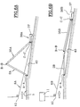
- FIG. 1 there is shown schematically in side view a first embodiment of the device of the invention, forming tilting barrier.
- the structure of the dam itself, the piers and the reinforcements, have not been shown.
- a dam door referenced 2 On the ground, forming the base of the dam, and bearing the general reference 1, there is hingedly mounted a dam door referenced 2, forming a valve.
- the door 2, articulated on the ground along a hinge axis AA, consists of at least one panel or plate of sheet metal, of rectangular shape and elongated in a direction transverse to the flow of the water, symbolized by the arrow f.
- the door 2 is capable, in its rotational movement around the axis AA, of taking several positions between a first extreme horizontal position substantially parallel to the ground, and a second raised extreme position where it bears the reference 20, corresponding to a position for maximum retention of the water contained in the dam upstream of the door.
- the stiffening beam consists of a longitudinal metal plate, in the direction transverse to the flow of the water (arrow f).
- the stiffening beam 3 has a length (direction transverse to the flow) substantially equivalent or very close to the length in the same direction, of the door 2.
- the stiffening beam 3 is mounted articulated on the door 2 along a longitudinal axis X-X relative to the door 2 and to the beam 3, and transverse to the flow of the water. More particularly, the beam is articulated on the panel 2 so that the upstream side 4 of the beam 3 is located near the upper side 5 (opposite the ground) of the door 2.
- the beam 3 in its position 30, is substantially perpendicular to the plane of the door 2.
- the door 2 is capable of being driven in rotation about the horizontal axis AA by any known means, such as for example one, and preferably two cables, of which only the cable 6 is visible in FIG. 1
- two cables are provided, references 6 and 7 (FIG. 4), the free end of each of which is fixed in rotation, along an axis YY, on the stiffening beam 3.
- the end of the cables 6 and 7 ( Figure 4) is fixed to the upstream end of transverse reinforcements, respectively 8 and 9 provided on the beam 3.
- the reinforcements 8 and 9 are arranged at the lateral ends of the stiffening beam 3 (see figure 4). The lateral reinforcements 8 and 9 protrude relative to the upstream side 4 of the stiffening beam 3.
- the axis YY of articulation of the cable on the lateral reinforcements 8 and 9 (and therefore on the beam 3) is offset towards the upstream with respect to the hinge axis XX of the beam 3 on the door 2 (see FIGS. 1 and 4).
- the cable 6 is shown in position 60 in the raised position 20 of the door 2, and in respective positions 61 and 62 for the intermediate positions 21 and 22 of the door 2.
- the cable 6 (the same applies to the cable 7) passes over a pulley 10 rotatably mounted, for example on a pile the dam (not shown); the end of the cable 6 is associated with drive motor means known in themselves but not described further in detail, and symbolized by the functional block 11.
- the double arrow g symbolizes the movement of the cable at the outlet of the motor means 11 to the return pulley 10.
- the actuation of the motor means 11 in the direction of the pull of the cable 6 in a direction opposite to the flow of the water ( arrow f), causes the door 2 to be raised, and therefore to rotate about the horizontal axis AA.
- the door 2 therefore forms an acute angle with the ground.
- the pull of the cable on the beam also causes the rotation of the beam 3 relative to the door 2.
- the beam 3 and the door 2 form, in the horizontal lowered position of the door 2, an angle substantially of 180 °; then, as door 2 is raised, the angle becomes less than 180 °.
- the beam 3 rests substantially on the ground 1.
- the beam 32 bears on the ground 1 only by its downstream end 12.
- the beam 3 is lifted from the ground in its upstream part (side 4) then that its downstream end 12 continues to rest on the ground and slides by this same downstream end 12 on the ground to the intermediate dotted position 32.
- the door 2 continues its rotational movement around the horizontal axis AA, and the beam 3 then no longer rests on the ground (see intermediate position 21, 61 and 31).
- the beam 31 In the intermediate position 21, 31 and 61 of the door, beam, cable assembly, the beam 31 has an obtuse angle (between 90 and 180 °) with the door 2.
- the door 2 continues its rotational movement to reach the raised position 20 where it is substantially vertical or at an angle close to 90 ° with the ground.
- the beam 3 is preferably arranged so that it forms a substantially right angle with the door 2.
- the beam 3 is intimately associated with the door 2, and has precisely in this transverse direction a very high rigidity. Indeed, the beam 3 being made up of a planar element, is very little deformable, or even undeformable in its plane, that is to say in the direction precisely of the buckling and bending forces to which the door 2 is subjected.
- FIG. 2 shows a schematic detail view on an enlarged scale of the means for securing in rotation the door 2 on the ground 1.
- a rigid metal rod bearing the reference 13 is arranged parallel to the ground, close to the latter. , and in a direction transverse to the flow of water, parallel to the door 2 and substantially the same length as the door 2.
- the rod 13 materializes the axis AA of rotation of the door 2 relative to the ground.
- the rod 13 is held relative to the ground by means of hoops 14 and 15 preferably arranged in pairs, so that the space between each hoop 14-15 of each couple can allow a hoop 16 to be arranged of U inside which the rod 13 is arranged, the arch 16 being itself made integral (by welding for example) with the door 2.
- FIG. 3 there is also shown schematically and on an enlarged scale, a detailed view of the means for rotationally fixing the door 2 relative to the beam 3.
- the two hoops 17 and 18 are arranged close to each other , and are made integral with a trunnion in the form of a metal rod 19. Between the arches 17 and 18, integral with the beam 2, a U-shaped hoop 25 can be arranged inside which the pin 19; the arch 25 is fixed to the beam 3 by welding, for example.
- the pin 19 materializes the axis of rotation XX of the beam 3 relative to the door 2.
- Figure 4 shows a top view of the beam 3 and the door 2, in the raised position of the door 2, where we find the elements described above, bearing the same references.
- the number and spacing of the hoop triplets 17, 18 and 19 ( Figure 3) is a function of the mechanical constraints and the general dimensions of the beam and the door.
- FIG 5 there is shown a schematic side view of the dam and in particular the structure comprising a pile 26, a buttress 27 resting on the ground 1.
- a support 28 is provided on the reinforcement 27 of the stack 26, and capable of serving as support for the beam 3, in the raised position of the door 2, that is to say in the position for which the beam 3 is substantially horizontal or slightly oblique.
- the support 28 thus makes it possible to avoid or minimize the effects of the vibrations to which the beam 3 could be subjected, due to the spillage of the water in the retaining position (corresponding to the raised position of the door 2).
- FIGS. 6A and 6B show in cross section an alternative embodiment of the invention, where elements of the same nature or similar have the same references, accompanied by an index A for the raised position of door 2 (FIG. 6A ) and an index B for the lowered position of door 2 ( Figure 6B).
- an index A for the raised position of door 2 FIG. 6A
- an index B for the lowered position of door 2 Figure 6B.
- a series of connecting rods 35A (of which only one is shown in Figures 6A and 6B).
- the other end of the connecting rod 35A is articulated, along an axis C-C, a beam 36A.
- the axis C-C is horizontal and close to the ground. Note that the axes of articulation A-A, B-B and C-C are materialized by pins, rods, cables or the like, in a known manner, and / or as described above and represented in FIGS. 2 and 3.
- the cable 6A is fixed at its free end (downstream) to the beam 36A.
- This has a shape similar to the beam 3 of Figures 1 and 4 and preferably has a longitudinal rib 37, so that the beam seen in cross section (in a plane parallel to the flow of water) forms a sort of L.
- the beam 36A thus rests on the ground by its upstream part (on the side of the articulation axis CC with the connecting rod 35A) and by the lower edge of the rib 37.
- the cable 6A is associated with a return pulley 10, and its other end is connected to drive means symbolized by a functional block 11. Only the cable 6A is visible in FIGS. 6A and 6B; two cables are provided, at each lateral end of the beam 36, in a similar manner to the embodiment shown in FIGS. 1 to 5.
- the apron of the dam downstream of the doors 2, is arranged so as to present a slight slope downstream, from the axis of articulation A-A.
- the operation of the device shown in Figures 6A and 6B is as follows.
- door 2 is thus allowed to pivot around the axis AA until it takes an extreme position lowered 2B shown in Figure 6B, for which it is substantially horizontal.
- the connecting rod 35B then has a substantially horizontal and slightly oblique direction, parallel to the sloping raft bearing the reference 40.
- the beam 36 slides on the downstream raft 40.
- the latter can be arranged to be provided with metal rods forming rails, regularly distributed over the strike off in a direction parallel to the flow of water. Note that such metal rods or sliding rails can also be provided in the embodiment shown in Figure 1, thus allowing the downstream end 12 of the beam 3 to slide on these rails. The latter have the advantage of making it possible to avoid wear and damage to the downstream raft 40.
- downstream ends of the cables 6 and 7 can be made integral with the upper side of the door 2 (on the side of the joint B-B of the connecting rods 35).
- Width of the beam (in the direction of water flow): 300-500 cm
- the cables 6 and 7 are capable, as a variant, of passing through slots provided on the door 2, and associated with lips made of flexible material to seal said slots.
Landscapes
- Engineering & Computer Science (AREA)
- Structural Engineering (AREA)
- General Engineering & Computer Science (AREA)
- Mechanical Engineering (AREA)
- Civil Engineering (AREA)
- Barrages (AREA)
- Special Wing (AREA)
Applications Claiming Priority (2)
| Application Number | Priority Date | Filing Date | Title |
|---|---|---|---|
| FR9505271 | 1995-05-03 | ||
| FR9505271A FR2733776B1 (fr) | 1995-05-03 | 1995-05-03 | Porte de barrage a surverse |
Publications (2)
| Publication Number | Publication Date |
|---|---|
| EP0741206A1 true EP0741206A1 (de) | 1996-11-06 |
| EP0741206B1 EP0741206B1 (de) | 2002-01-23 |
Family
ID=9478653
Family Applications (1)
| Application Number | Title | Priority Date | Filing Date |
|---|---|---|---|
| EP19960400709 Expired - Lifetime EP0741206B1 (de) | 1995-05-03 | 1996-04-02 | Überlaufklappenwehr |
Country Status (4)
| Country | Link |
|---|---|
| EP (1) | EP0741206B1 (de) |
| DE (1) | DE69618704T2 (de) |
| ES (1) | ES2171627T3 (de) |
| FR (1) | FR2733776B1 (de) |
Cited By (1)
| Publication number | Priority date | Publication date | Assignee | Title |
|---|---|---|---|---|
| FR2784404A1 (fr) * | 1998-10-13 | 2000-04-14 | Parisienne De Rech Appliquees | Barrage a surverse a panneau basculant |
Families Citing this family (2)
| Publication number | Priority date | Publication date | Assignee | Title |
|---|---|---|---|---|
| DE102004013367A1 (de) * | 2004-03-17 | 2005-10-13 | Michael Seibert | Vorrichtung zur Errichtung eines Wasserparcours |
| RU2315151C1 (ru) * | 2006-05-19 | 2008-01-20 | Открытое акционерное общество "Гипроречтранс" | Складной затвор |
Citations (5)
| Publication number | Priority date | Publication date | Assignee | Title |
|---|---|---|---|---|
| CH246437A (de) * | 1945-04-19 | 1947-01-15 | Wartmann & Cie | Segmentwehr mit Überfallklappe. |
| DE758858C (de) * | 1940-02-10 | 1953-08-17 | Arno Fischer | Stauklappe mit zwei zusammenfaltbaren Klappenteilen |
| DE1287520B (de) * | 1967-04-27 | 1969-01-16 | Voith Gmbh J M | Stauklappe fuer ueberstroemte Wehre mit mindestens einem einstellbaren Strahlaufreisser |
| JPS57172016A (en) * | 1981-04-16 | 1982-10-22 | Mitsubishi Heavy Ind Ltd | Sluice door |
| CH640289A5 (en) * | 1981-01-21 | 1983-12-30 | Vevey Atel Const Mec | Dam element |
-
1995
- 1995-05-03 FR FR9505271A patent/FR2733776B1/fr not_active Expired - Fee Related
-
1996
- 1996-04-02 ES ES96400709T patent/ES2171627T3/es not_active Expired - Lifetime
- 1996-04-02 DE DE1996618704 patent/DE69618704T2/de not_active Expired - Fee Related
- 1996-04-02 EP EP19960400709 patent/EP0741206B1/de not_active Expired - Lifetime
Patent Citations (5)
| Publication number | Priority date | Publication date | Assignee | Title |
|---|---|---|---|---|
| DE758858C (de) * | 1940-02-10 | 1953-08-17 | Arno Fischer | Stauklappe mit zwei zusammenfaltbaren Klappenteilen |
| CH246437A (de) * | 1945-04-19 | 1947-01-15 | Wartmann & Cie | Segmentwehr mit Überfallklappe. |
| DE1287520B (de) * | 1967-04-27 | 1969-01-16 | Voith Gmbh J M | Stauklappe fuer ueberstroemte Wehre mit mindestens einem einstellbaren Strahlaufreisser |
| CH640289A5 (en) * | 1981-01-21 | 1983-12-30 | Vevey Atel Const Mec | Dam element |
| JPS57172016A (en) * | 1981-04-16 | 1982-10-22 | Mitsubishi Heavy Ind Ltd | Sluice door |
Non-Patent Citations (1)
| Title |
|---|
| PATENT ABSTRACTS OF JAPAN vol. 7, no. 16 (M - 187)<1161> 22 January 1983 (1983-01-22) * |
Cited By (2)
| Publication number | Priority date | Publication date | Assignee | Title |
|---|---|---|---|---|
| FR2784404A1 (fr) * | 1998-10-13 | 2000-04-14 | Parisienne De Rech Appliquees | Barrage a surverse a panneau basculant |
| EP0994219A1 (de) * | 1998-10-13 | 2000-04-19 | Societe Parisienne De Recherches Appliquees | Überströmtes Wehr mit kippbarer Wehrklappe |
Also Published As
| Publication number | Publication date |
|---|---|
| FR2733776B1 (fr) | 1997-06-13 |
| EP0741206B1 (de) | 2002-01-23 |
| DE69618704T2 (de) | 2002-09-12 |
| DE69618704D1 (de) | 2002-03-14 |
| ES2171627T3 (es) | 2002-09-16 |
| FR2733776A1 (fr) | 1996-11-08 |
Similar Documents
| Publication | Publication Date | Title |
|---|---|---|
| FR2954789A1 (fr) | Abri mobile pour piscine | |
| EP0741206B1 (de) | Überlaufklappenwehr | |
| EP0381904B1 (de) | Reinigungsvorrichtung für überhängende Flächen, wie Decken und Rundbogen | |
| FR2673671A1 (fr) | Patin de glissement pour porte de manutention a rideau relevable. | |
| EP0841003A1 (de) | Räumgerät zum Entmisten | |
| EP2635759B1 (de) | Jalousierbarer rollladen | |
| CA1332865C (fr) | Volet roulant pour fenetre de toiture | |
| EP0994219A1 (de) | Überströmtes Wehr mit kippbarer Wehrklappe | |
| BE1011372A3 (fr) | Barrage susceptible d'etre leve et abaisse pour cours d'eau. | |
| FR2765606A1 (fr) | Poutrelle de support pour un caillebotis de piscine enterree | |
| EP2118418A1 (de) | Scharniersystem für ein sektionaltor, sektionaltor und befestigungsverfahren dafür | |
| EP0165113A1 (de) | Vorrichtung zum Decken und Abdecken eines Laderaums | |
| EP0374194B1 (de) | Antriebssystem und anwendungsverfahren für auf einer schiene bewegbare wagen | |
| FR2737513A1 (fr) | Structure de travure destinee en particulier au franchissement de breches par des vehicules et systeme de transfert et de depose d'une telle structure | |
| EP0225268B1 (de) | Ladevorrichtung für Müllsammelbehälter auf Müllfahrzeugen | |
| FR2746842A1 (fr) | Porte a mouvement vertical | |
| EP1100995B1 (de) | Stützvorrichtung für eine bewegliche last | |
| FR2789437A1 (fr) | Dispositif anti-relevage de securite de volet roulant | |
| FR2797245A1 (fr) | Caisse de vehicule de transport routier et vehicule de transport routier pourvu d'une telle caisse | |
| FR2735431A3 (fr) | Dispositif pour le chargement et le dechargement de charges dans des camions | |
| EP0643191A1 (de) | Schiebeflügel | |
| FR2660337A1 (fr) | Dispositif de derasement d'accotement combine a un godet de curage de fosses. | |
| BE890367A (fr) | Pont telescopique. | |
| FR2983506A1 (fr) | Abri repliable comprenant des moyens motorises d'empilement d'elements de toiture, et procede d'ouverture d'un tel abri | |
| FR2777031A1 (fr) | Deflecteur pour couverture de piscine |
Legal Events
| Date | Code | Title | Description |
|---|---|---|---|
| PUAI | Public reference made under article 153(3) epc to a published international application that has entered the european phase |
Free format text: ORIGINAL CODE: 0009012 |
|
| AK | Designated contracting states |
Kind code of ref document: A1 Designated state(s): DE ES GB IT |
|
| 17P | Request for examination filed |
Effective date: 19961216 |
|
| GRAG | Despatch of communication of intention to grant |
Free format text: ORIGINAL CODE: EPIDOS AGRA |
|
| 17Q | First examination report despatched |
Effective date: 20010323 |
|
| GRAG | Despatch of communication of intention to grant |
Free format text: ORIGINAL CODE: EPIDOS AGRA |
|
| GRAG | Despatch of communication of intention to grant |
Free format text: ORIGINAL CODE: EPIDOS AGRA |
|
| GRAH | Despatch of communication of intention to grant a patent |
Free format text: ORIGINAL CODE: EPIDOS IGRA |
|
| GRAH | Despatch of communication of intention to grant a patent |
Free format text: ORIGINAL CODE: EPIDOS IGRA |
|
| GRAA | (expected) grant |
Free format text: ORIGINAL CODE: 0009210 |
|
| REG | Reference to a national code |
Ref country code: GB Ref legal event code: IF02 |
|
| AK | Designated contracting states |
Kind code of ref document: B1 Designated state(s): DE ES GB IT |
|
| REF | Corresponds to: |
Ref document number: 69618704 Country of ref document: DE Date of ref document: 20020314 |
|
| GBT | Gb: translation of ep patent filed (gb section 77(6)(a)/1977) |
Effective date: 20020430 |
|
| REG | Reference to a national code |
Ref country code: ES Ref legal event code: FG2A Ref document number: 2171627 Country of ref document: ES Kind code of ref document: T3 |
|
| PLBE | No opposition filed within time limit |
Free format text: ORIGINAL CODE: 0009261 |
|
| STAA | Information on the status of an ep patent application or granted ep patent |
Free format text: STATUS: NO OPPOSITION FILED WITHIN TIME LIMIT |
|
| 26N | No opposition filed | ||
| PGFP | Annual fee paid to national office [announced via postgrant information from national office to epo] |
Ref country code: ES Payment date: 20090428 Year of fee payment: 14 |
|
| PGFP | Annual fee paid to national office [announced via postgrant information from national office to epo] |
Ref country code: IT Payment date: 20090430 Year of fee payment: 14 Ref country code: DE Payment date: 20090508 Year of fee payment: 14 |
|
| PGFP | Annual fee paid to national office [announced via postgrant information from national office to epo] |
Ref country code: GB Payment date: 20090505 Year of fee payment: 14 |
|
| GBPC | Gb: european patent ceased through non-payment of renewal fee |
Effective date: 20100402 |
|
| PG25 | Lapsed in a contracting state [announced via postgrant information from national office to epo] |
Ref country code: DE Free format text: LAPSE BECAUSE OF NON-PAYMENT OF DUE FEES Effective date: 20101103 |
|
| PG25 | Lapsed in a contracting state [announced via postgrant information from national office to epo] |
Ref country code: GB Free format text: LAPSE BECAUSE OF NON-PAYMENT OF DUE FEES Effective date: 20100402 Ref country code: IT Free format text: LAPSE BECAUSE OF NON-PAYMENT OF DUE FEES Effective date: 20100402 |
|
| REG | Reference to a national code |
Ref country code: ES Ref legal event code: FD2A Effective date: 20110715 |
|
| PG25 | Lapsed in a contracting state [announced via postgrant information from national office to epo] |
Ref country code: ES Free format text: LAPSE BECAUSE OF NON-PAYMENT OF DUE FEES Effective date: 20110705 |
|
| PG25 | Lapsed in a contracting state [announced via postgrant information from national office to epo] |
Ref country code: ES Free format text: LAPSE BECAUSE OF NON-PAYMENT OF DUE FEES Effective date: 20100403 |