EP0740232B1 - Dispositif de fixation d'un cadran de montre - Google Patents
Dispositif de fixation d'un cadran de montre Download PDFInfo
- Publication number
- EP0740232B1 EP0740232B1 EP96106270A EP96106270A EP0740232B1 EP 0740232 B1 EP0740232 B1 EP 0740232B1 EP 96106270 A EP96106270 A EP 96106270A EP 96106270 A EP96106270 A EP 96106270A EP 0740232 B1 EP0740232 B1 EP 0740232B1
- Authority
- EP
- European Patent Office
- Prior art keywords
- dial
- timepiece according
- hold
- annular element
- ring
- Prior art date
- Legal status (The legal status is an assumption and is not a legal conclusion. Google has not performed a legal analysis and makes no representation as to the accuracy of the status listed.)
- Expired - Lifetime
Links
- 230000002093 peripheral effect Effects 0.000 claims description 6
- 238000005520 cutting process Methods 0.000 claims description 5
- 238000002347 injection Methods 0.000 claims 1
- 239000007924 injection Substances 0.000 claims 1
- 229910001369 Brass Inorganic materials 0.000 description 9
- 239000010951 brass Substances 0.000 description 9
- 239000012790 adhesive layer Substances 0.000 description 7
- 239000010410 layer Substances 0.000 description 4
- 241000283070 Equus zebra Species 0.000 description 3
- 239000000853 adhesive Substances 0.000 description 3
- 230000001070 adhesive effect Effects 0.000 description 3
- 238000004873 anchoring Methods 0.000 description 2
- 230000000694 effects Effects 0.000 description 2
- 238000010292 electrical insulation Methods 0.000 description 2
- 238000004519 manufacturing process Methods 0.000 description 2
- 239000002184 metal Substances 0.000 description 2
- 238000000034 method Methods 0.000 description 2
- 238000004040 coloring Methods 0.000 description 1
- 239000004020 conductor Substances 0.000 description 1
- 239000011521 glass Substances 0.000 description 1
- 239000003292 glue Substances 0.000 description 1
- 238000002955 isolation Methods 0.000 description 1
- 230000002045 lasting effect Effects 0.000 description 1
- 230000001795 light effect Effects 0.000 description 1
- 239000000203 mixture Substances 0.000 description 1
- 229920000642 polymer Polymers 0.000 description 1
- 230000000284 resting effect Effects 0.000 description 1
- 239000007787 solid Substances 0.000 description 1
- 238000003892 spreading Methods 0.000 description 1
Images


Classifications
-
- G—PHYSICS
- G04—HOROLOGY
- G04B—MECHANICALLY-DRIVEN CLOCKS OR WATCHES; MECHANICAL PARTS OF CLOCKS OR WATCHES IN GENERAL; TIME PIECES USING THE POSITION OF THE SUN, MOON OR STARS
- G04B19/00—Indicating the time by visual means
- G04B19/06—Dials
- G04B19/14—Fastening the dials to the clock or watch plates
-
- G—PHYSICS
- G04—HOROLOGY
- G04B—MECHANICALLY-DRIVEN CLOCKS OR WATCHES; MECHANICAL PARTS OF CLOCKS OR WATCHES IN GENERAL; TIME PIECES USING THE POSITION OF THE SUN, MOON OR STARS
- G04B19/00—Indicating the time by visual means
- G04B19/30—Illumination of dials or hands
Definitions
- the invention relates to a device for fastening a clock face according to the generic term of claim 1.
- the device according to the invention intended for watches with electroluminescent dials.
- Electroluminescent dials are known to have basically two electrodes and an intermediate one electroluminescent layer. The one on the top The electrode is transparent. As a result of one on the electrodes applied voltage becomes the electroluminescent Layer shone. The light effect is through the transparent electrode for the watch holder visible.
- Patent CH 30 614 shows a watch with a Base part in the form of a work plate, a dial and an annular ring resting on the dial Element, with the annular element in the dial at least partially covers its peripheral area and is fastened in the base part by fastening means.
- the dial lies directly on the work surface and the annular element is said to protect the Dial in the event of glass breakage.
- the fasteners arranged so that a simple and quick assembly and disassembly of the dial on or from the base part is not possible.
- Patent US 4 150 538 shows a watch with a Base part, a dial and a case ring that the Clockwork surrounds and as an element for fastening the Dial serves.
- the dial is therefore with Feet provided in holes in the housing ring are arranged. With the help of this device it is however not possible a flat, even and to ensure permanent circulation of the dial.
- the present invention is therefore based on the object to create a device which a flat, even and permanent support of the dial guaranteed on the dial carrier and a easy to assemble and disassemble from the dial and its unit formed on or from a base element, such as a circuit board or a movement retaining ring.
- the device according to the invention has compared to the State of the art has the following advantages:
- the solution according to the invention has an annular shape Provides fasteners that the dial in its peripheral area on the dial support presses can be a flat, even and lasting Guaranteed support of the dial on the dial carrier become. It also becomes a simple one Assemble and disassemble the from the dial, the Dial carrier and the ring-shaped fastener formed unit on or from a base element, such as for example a circuit board or a work retaining ring, allows.
- Dial carrier and the ring-shaped fastener provided rivet-shaped fastening pins, which ensure solid cohesion.
- the fastening pins on the ring-shaped fastening means welded are the fastening pins on the ring-shaped fastening means welded. This means that in addition to assembly the unit on the base element also the possibility be provided, the dial support, the dial and then the annular fastener one after the other to put directly on the base element.
- the movement retaining ring 13 and the movement 10 On the top of the movement holder ring 13 and the movement 10 is a round, the movement retaining ring 13 and that Movement 10 dial carrier completely covering this side 14 made of brass, for example.
- the already known composition is not shown of the dial 16, which consists essentially of two Electrodes and an intermediate electroluminescent Layer.
- a supply circuit, not shown, is in the work retaining ring 13 conventional type provided, which of a battery, also not shown DC voltage converts to an appropriate glow of the electroluminescent dial 16 is made possible.
- the dial 16 can not have a here shown, designed as a momentary push button be switched on.
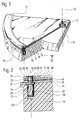
- a flat-shaped, annular On the dial 16 is in the area of its periphery a flat-shaped, annular, in the following with hold-down ring 17 designated fastener Brass arranged, in which according to Fig.1 in the direction an axis 18 which runs parallel to the axis of rotation 12, a through hole 19 is formed.
- fastener Brass arranged, in which according to Fig.1 in the direction an axis 18 which runs parallel to the axis of rotation 12, a through hole 19 is formed.
- the following relates the description is based on that shown in Fig.1 Area of the axis 18, which is clearer as a detail section Fig.2 emerges.
- the representative mounting pin shown in Figure 2 25 has a longer, cylindrical shaft 26 on in the adhesive seat in the hole area 23 of the blind hole 22nd sitting. At the top of this shaft 26 is a thin, annular flange 27 which in the short hole area 24 Find space.
- the flange 27 has one on its top annular bearing surface 28, which is flush with the top the movement retaining ring 13.
- the dial carrier 14 lies thus also on the contact surface 28 of the flange 27.
- the fastening pin 25 is connected to the flange 27 a short area 29, which is in the through hole 21 of the dial support 14 is located. In the field of The adhesive layer 15 tapers the fastening pin 25, i.e. the short area 29 goes into a longer area 30 with a smaller diameter.
- This area 30 does not fill the through hole 20 of the dial 16 completely, but leaves a substantially hollow cylindrical Free space 31 arise, the electrical Isolation between the dial 16 and the Securing pin 25 ensures.
- the area 30 of the fastening pin 25 also leads through the through hole 19 of the hold-down ring 17 through and opens into a flattened rivet head 32 shown in an expanded area 33 of the through hole 19 space takes place so that the rivet head 32 in the hold-down ring 17 is sunk and the latter is still on a level Surface 34 has.
- the Rivet head 32 On its underside, the Rivet head 32 has a bearing surface 35, which on the hold-down ring 17 rests.
- dial 16 and hold-down ring 17 initially by means of the fastening pins 25 riveted to a compact unit, hereinafter referred to as Dial unit is called.
- This dial unit can be stored temporarily or immediately afterwards as a whole on the movement 10 or the movement retaining ring 17 are plugged in, the shafts 26 of the fastening pins 25 in the blind holes 22 of the movement retaining ring 13 Find a stop.
- With two to three mounting pins 25 is a sufficiently secure anchoring of the hold-down ring 17 possible in movement holder ring 13. It goes without saying a corresponding number of holes 19 to 22 are provided.
- the dial carrier 14, the hold-down ring 17 and the mounting pins 25 made of brass prevents the electrically insulating adhesive layer 15 and the hollow cylindrical free space 31 the short circuit of the two electrodes of the dial 16 with each other.
- the one needed to light up the dial electrical energy via two from the factory retaining ring 13 outstanding spring contacts fed.
- FIG. 3 is another embodiment designated 17 ' of the hold-down ring shown in FIGS. 1 and 2 17 shown.
- the hold-down ring 17 ' are on the underside several, advantageously two to three fastening pins 25 'welded, similar to conventional ones Dials and their dial feet is known so that the hold-down ring 17 'has a flat surface 34' having.
- the tapers Mounting pin 25 ' i.e. the shaft 26 'goes into one cylindrical area 30 'with a smaller diameter.
- the area 30 'fills the through hole 20 of the dial 16 is not completely omitted, but as in Embodiment of Figures 1 and 2 a hollow cylindrical Free space 31 'arise of the electrical insulation between the dial 16 and the fastening pin 25 'ensures.
- the axis 41 at least runs approximately parallel to the axis 18 ', is an immediate next to the fastening pin 25 'arranged, rotatable Dial latch 42 used, which in itself is already known.
- the dial latch 42 has one Head 43 partially concentric with axis 41 arranged cutting edge 44 is surrounded, and a first cylindrical part 45 and a second, in diameter somewhat smaller cylindrical part 46.
- the diameter of the first, cylindrical part 45 enables an adhesive seat of the dial bolt 42 inserted into the bore 40.
- the head 43 also has a slot 47 for attachment a screwdriver-like tool, not shown on.
- Part of the head 43 and the cutting edge 44 is along a cutting plane, preferably parallel to axis 41, forming a cut surface 48, separated. In Fig.3 is this cut surface 48 on the to the mounting pin 25 'shown opposite side.
- This rotational position of the The dial bolt 42 penetrates the cutting edge 44 into the fastening pin 25 'and anchors it in the direction of the Axis 18 'out. Such anchoring is for everyone Fastening pin 25 'provided.
- Analogous to the exemplary embodiment shown in FIGS. 1 and 2 can also in that of Figure 3 from Dial carrier 14, dial 16 and hold-down ring 17 'existing dial unit pre-assembled and if necessary be temporarily stored.
- the cohesion of this Unit is in the embodiment shown in Fig.3 but not by riveting, but by one Adhesive seat in the through holes 21 of the dial support 14 located fixing pins 25 'guaranteed.
- dial unit it is in the embodiment according to FIG also possible on pre-assembling the dial unit to dispense with and the coated with the adhesive layer 15 Dial carrier 14 together with the dial 16 as Position the subunit directly on the movement retaining ring 13. Then the hold-down ring 17 'with its welded on Fastening pins 25 'placed over it again the short cylindrical hollow cylinder Open spaces 31 must arise and the in the holes 40 of the clockwork 13 located dial latch 42 must be aligned so that the Cut surfaces 48 in the immediate vicinity of the mounting pins 25 'come to rest. Then the hold-down ring 17 'by rotating the dial latch 42 anchored about half a turn.
- a suitable tool which is not shown here the now compact dial unit can remove as a whole from the work retaining ring 13, for example a dial 16 of another design to be able to use.
- the disassembled dial unit can be used with another movement.
- the top electrode can be directly through the Hold-down ring 17 'can be contacted, at least a fastening pin 25 'and the associated, for example female contact socket formed blind hole 22 the electrical connection between the hold-down ring 17 'and the feed circuit, not shown, in the factory retaining ring 13 ensures.
- the underlying electrode of the dial 16 can be contacted directly through the dial carrier 14 be electrically here by the adhesive layer 15 is leading.
- a protruding from the movement holder ring 13 Contact spring, a zebra contact or just a conductor track only touches the underside of the dial support 14 and no longer presses the dial 16 self.
- rotating dial latches 42 according to FIG. 3 also for those shown in FIGS. 1 and 2 Embodiment are provided, thereby on a press fit of the fastening pins 25 can be dispensed with can.
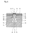
- FIGS. 4 to 6 show three further embodiments the hold-down rings 17 and 17 'shown.
- the dial support 14 can its through holes 21 and the dial 16 with its through holes 20 remain unchanged. Different only the one previously designated 13 is formed Movement retaining ring as well as the previously 17 or 17 ' designated hold-down ring with its fastening pins 25 or 25 '.
- FIG. 4 shows a hold-down ring 50 which has several, preferably three angled tabs, one of which is shown here and designated 51.
- These tabs 51 which are also referred to as legs, are also included the hold-down ring 50 is formed from one piece, preferably stamped from a sheet brass.
- a first straight leg region 52 of the tab 51 shown extends approximately along axis 18 through the through holes 20 and 21 and thus approximately orthogonal to the plane of the Hold-down ring 50.
- At this first leg area 52 concludes a second one, with respect to those not shown here Axis of rotation 12 against the outwardly curved leg region 53, which is located in a first hole area 54 of the here with 55 designated retaining ring.
- In connection to the leg region 53 bent outwards follows a leg region 56 which is bent towards the inside and which in a second hole area 57 which is in relation to the hole area 54 larger in diameter and length and is designed as a blind hole.
- the leg regions 56 each extend from the axis 18 beyond the hole area 54, wherein about at the point at which the person faces the outside curved leg region 53 to be bent towards the inside Leg region 56 merges, at one of the two Hole areas 54 and 57 formed circular edge 58th at two contact points, not shown.
- the tabs 51 are under spring tension and essentially press with respect to the axis of rotation 12 with a radial and an axial component outwards in the direction of arrow 59, whereby the hold-down ring 50 is anchored on the movement retaining ring 55.
- cylindrical hole areas 54 and 57 can square hole areas, which are not shown here, not to be provided, as described above, to create a point support, but a line support, which has several advantages, including less is sensitive.
- FIG. 5 shows a hold-down ring 60, which is also has several, preferably three angled tabs, one of which is shown here and labeled 61 is.
- These tabs 61 and the hold-down ring 60 are also here formed from one piece, preferably from a sheet brass punched.
- the difference of the tab 61 compared that of Figure 4 is only that they in the direction of the axis 18 a first leg 62 and a second leg 63 are divided into two, wherein this with a fictitious rotation of 180 ° about the axis 18 merge.
- the first leg 62 like the flap 51 a leg region bent towards the outside 64 and a leg area bent towards the inside 65 and the second leg 63 one bent towards the inside Leg area 66 and a leg area bent towards the outside 67 on.
- FIG. 6 shows a hold-down ring 70 which again several, preferably three angled tabs , one of which is shown and designated 71 is. These tabs 71 are with the hold-down ring 70 formed together from one piece, preferably also punched out of a brass sheet. Like the tab of Fig.5 the tab 70 is also divided in two, i.e. she shows one first leg 72 and one with respect to that shown in FIG Axis of rotation 12 peripherally adjacent, second leg 73, which is congruent mirrored on the axis 18 are. Both legs 72 and 73 are in contrast to 4 and 5 not in radial with respect to the axis of rotation 12 Formed curved.
- the hold-down rings 50, 60 and 70 only attached when the dial carrier 14 and Dial 16 already as a unit on the movement holder ring 55 are positioned.
- the hold-down rings shown in Fig. 4, 5 and 6 50, 60 and 70 can, as already mentioned above for the Case of Figure 3 was recorded as a contact element serve the upper electrode of the dial 16. Analogous can again be provided in the 55 retaining ring become.
- so-called zebra contacts be used, which is a conductive, foam-like Have area that to the electrodes of the Dial 16 presses.
- the hold-down ring can be above its original Task beyond, as a mechanical fastener too act, also serve as a carrier of information.
- the hold-down ring can, for example its top 34 lines, digits, time zone or Show any other information. On the presentation such indices are omitted in the figures Service.
- the hold-down ring can also be used as a design element serve. For example, it results from a compared to the dial 16 different coloring or pattern a decorative effect. With that in mind, it can be useful, not only the hold-down ring shown in Fig.3 17 ', 50, 60 and 70 made of plastic, but also those designated by 17 from FIGS. 1 and 2, the rivet-shaped fastening pins 25 as before advantageously consist of a metal. If the Hold down ring not visible for the watch wearer the watch case must be shaped accordingly, or the size ratio between the watch case and Dial 16 should be chosen so that the hold-down ring remains hidden.
- Hold-down ring also for non-electroluminescent To provide dials. For example, at Dials will be the case as photographic portraits are trained.
- the hold-down ring prevents thereby caused by the air humidity Ripple of the recording.
- the inventive Device a simple, if necessary multiple Assemble and disassemble the from the dial, the Dial support and the hold-down ring formed unit on or from a base element, such as a circuit board or a work retaining ring. Prefabricated dial units of various designs can be stored as a whole and assembled if necessary become.
Landscapes
- Physics & Mathematics (AREA)
- General Physics & Mathematics (AREA)
- Details Of Measuring And Other Instruments (AREA)
- Electric Clocks (AREA)
Claims (11)
- Montre comprenant une pièce de base (13, 55), un cadran (16) et, disposé sur le cadran (16), un élément de forme annulaire (17, 17', 50, 60, 70) qui est fixé à la pièce de base (13, 55) par l'intermédiaire de moyens de fixation (25, 25', 51, 61, 71) et qui couvre le cadran (16) au moins en partie dans sa région périphérique, caractérisée en ce que :un support de cadran (14) est disposé entre la pièce de base (13, 55) et le cadran (16);le cadran (16) est collé sur le support de cadran (14); etles moyens de fixation (25, 25', 51, 61, 71) sont associés fixement à l'élément de forme annulaire (17, 17', 50, 60, 70) et présentent chacun au moins une partie proéminente (26, 26', 51, 61, 62, 63, 71, 72, 73) qui est disposée dans des évidements (22, 23, 24, 54, 57) de la pièce de base (13, 55) parallèlement à un axe de rotation (12) d'une aiguille de la montre.
- Montre selon la revendication 1, caractérisée en ce que les parties proéminentes ont essentiellement la forme de tiges cylindriques (26, 26') et sont disposés dans des évidements ayant la forme de trous (22, 23, 24).
- Montre selon la revendication 2, caractérisée en ce que les moyens de fixation (25') et l'élément de forme annulaire (17') sont moulés par injection en une seule pièce.
- Montre selon la revendication 2, caractérisée en ce que les moyens de fixation (25') sont soudés à l'élément de forme annulaire (17').
- Montre selon la revendication 2, caractérisée en ce que les moyens de fixation (25) présentent chacun une région formant rivet (28, 29, 30, 32, 35) qui encadre au moins l'élément de forme annulaire (17) et le cadran (16).
- Montre selon la revendication 2, caractérisée en ce que les tiges cylindriques (26) sont chassées dans au moins une région (23) des trous.
- Montre selon la revendication 2, caractérisée en ce que les tiges cylindriques (26') sont fixés chacune dans les trous (22, 23, 24) au moyen d'un verrou de cadran (42) adjacent possédant un bord aiguisé (44) ayant la forme d'un disque.
- Montre selon la revendication 1, caractérisée en ce que les moyens de fixation (51, 61, 71) et l'élément de forme annulaire (50, 60, 70) sont réalisés en une seule pièce et que les parties proéminentes ont la forme de languettes (51, 61, 71) et sont disposées dans des évidements ayant la forme de trous (54, 57).
- Montre selon la revendication 1, caractérisée en ce que le cadran (16) est un cadran électroluminescent.
- Montre selon la revendication 9, caractérisée en ce qu'une électrode supérieure du cadran électroluminescent (16) est contactée directement au moyen de l'élément de forme annulaire (17, 17', 50, 60, 70).
- Montre selon la revendication 10, caractérisée en ce qu'au moins un élément de fixation (25, 25', 51, 61, 71) assure une connexion électrique entre l'élément de forme annulaire (17, 17', 50, 60, 70) et un circuit d'alimentation du cadran électroluminescent (16).
Applications Claiming Priority (3)
| Application Number | Priority Date | Filing Date | Title |
|---|---|---|---|
| CH117495 | 1995-04-25 | ||
| CH1174/95 | 1995-04-25 | ||
| CH01174/95A CH687898B5 (de) | 1995-04-25 | 1995-04-25 | Uhr mit einem elektrolumineszenten Zifferblatt. |
Publications (2)
| Publication Number | Publication Date |
|---|---|
| EP0740232A1 EP0740232A1 (fr) | 1996-10-30 |
| EP0740232B1 true EP0740232B1 (fr) | 2002-01-23 |
Family
ID=4204232
Family Applications (1)
| Application Number | Title | Priority Date | Filing Date |
|---|---|---|---|
| EP96106270A Expired - Lifetime EP0740232B1 (fr) | 1995-04-25 | 1996-04-22 | Dispositif de fixation d'un cadran de montre |
Country Status (9)
| Country | Link |
|---|---|
| US (1) | US5699324A (fr) |
| EP (1) | EP0740232B1 (fr) |
| JP (1) | JPH08304563A (fr) |
| KR (1) | KR100416572B1 (fr) |
| CN (1) | CN1139013C (fr) |
| CH (1) | CH687898B5 (fr) |
| DE (1) | DE59608623D1 (fr) |
| SG (1) | SG86978A1 (fr) |
| TW (1) | TW289809B (fr) |
Families Citing this family (12)
| Publication number | Priority date | Publication date | Assignee | Title |
|---|---|---|---|---|
| TW538324B (en) * | 2001-07-12 | 2003-06-21 | Ebauchesfabrik Eta Ag | Device for securing a dial in a watchcase |
| WO2008068282A1 (fr) * | 2006-12-07 | 2008-06-12 | Montres Breguet Sa | Boîte protectrice pour le transport ou le stockage d'une pièce ayant la forme d'une plaque percée d'une ouverture |
| CN102037433B (zh) * | 2008-05-30 | 2013-06-05 | 日本写真印刷株式会社 | 带触摸输入功能的保护面板的安装结构以及安装方法 |
| EP2455822B1 (fr) * | 2010-11-23 | 2017-11-15 | ETA SA Manufacture Horlogère Suisse | Procédé et dispositif de fixation d'un élément d'affichage |
| EP2595008B1 (fr) * | 2011-11-17 | 2015-01-07 | Montres Rado S.A. | Boîte pour pièce d'horlogerie |
| US12078966B2 (en) | 2019-07-25 | 2024-09-03 | Casio Computer Co., Ltd. | Dial, module, electronic device and timepiece |
| JP7571721B2 (ja) * | 2019-07-25 | 2024-10-23 | カシオ計算機株式会社 | モジュールの製造方法、時計の製造方法、モジュールの分解方法、時計の分解方法、モジュールおよび時計 |
| WO2021104698A1 (fr) * | 2019-11-26 | 2021-06-03 | Rolex Sa | Bague de liaison pour cadran horloger, plaque de cadran horloger et procédé d'assemblage de cadran horloger. |
| EP3832396B1 (fr) * | 2019-12-03 | 2024-01-24 | ETA SA Manufacture Horlogère Suisse | Dispositif de fixation d'un element d'affichage ou d'habillage d'horlogerie |
| EP4083717A1 (fr) * | 2021-04-29 | 2022-11-02 | Rolex Sa | Pied pour cadran horloger, plaque pour cadran horloger et cadran horloger |
| EP4134755A1 (fr) * | 2021-08-09 | 2023-02-15 | ETA SA Manufacture Horlogère Suisse | Clef de maintien d'un cadran à la platine d'un mouvement horloger |
| EP4194966B1 (fr) * | 2021-12-07 | 2025-12-03 | ETA SA Manufacture Horlogère Suisse | Verrou destiné à limiter le débattement axial d'un mobile d'un mouvement horloger et mouvement horloger le comportant |
Family Cites Families (14)
| Publication number | Priority date | Publication date | Assignee | Title |
|---|---|---|---|---|
| CH30614A (fr) * | 1904-05-17 | 1905-01-15 | Abraham Anzelewitz | Montre avec dispositif d'ajustement du cadran |
| US1074130A (en) * | 1912-07-02 | 1913-09-30 | William B Miller | Dial-fastening device for watches. |
| CH77267A (fr) * | 1917-11-01 | 1918-04-01 | Brandt Calame Henri | Dispositif de fixation d'un cadran à une pièce d'horlogerie |
| CH225819A (fr) * | 1942-02-03 | 1943-02-28 | Schwaab Albert | Procédé de fabrication de cadrans à pieds, et cadran à pieds obtenu au moyen de ce procédé. |
| CH353310A (fr) * | 1959-07-17 | 1961-03-31 | Tissot Horlogerie | Dispositif d'assemblage et de fixation de deux éléments d'un appareil de précision |
| FR1447578A (fr) * | 1964-09-10 | 1966-07-29 | Philips Nv | Procédé de fabrication d'une cathode photosensible constituée par de l'argent, de l'oxygène et un métal alcalin |
| FR1448578A (fr) * | 1965-09-29 | 1966-08-05 | Lapidor Sa | Pièce d'horlogerie |
| DE2028523A1 (de) * | 1970-01-29 | 1971-08-12 | Ruhla Uhren Veb K | Zifferblattbefestigung mit Werkfixie rung fur Uhren |
| CH610705B (de) * | 1975-09-12 | Ebauchesfabrik Eta Ag | Vorrichtung zum befestigen eines zifferblattes an einer werkplatte einer uhr. | |
| DE7624675U1 (de) * | 1976-08-05 | 1976-11-25 | Kienzle Uhrenfabriken Gmbh, 7220 Schwenningen | Zentrale werkbefestigung fuer uhren |
| US4150538A (en) * | 1977-11-08 | 1979-04-24 | Citizen Watch Company Limited | Dial attaching device for watch |
| KR890002288Y1 (ko) * | 1986-05-15 | 1989-04-15 | 삼성시계 주식회사 | 손목시계의 베젤 고정구조 |
| CH683582B5 (fr) * | 1992-06-30 | 1994-10-14 | Ebauchesfabrik Eta Ag | Pièce d'horlogerie comportant un élément fixé rigidement sur une pièce de base en matière plastique. |
| US5265071A (en) * | 1993-02-02 | 1993-11-23 | Timex Corporation | Electroluminescent watch dial support and connector assembly |
-
1995
- 1995-04-25 CH CH01174/95A patent/CH687898B5/de not_active IP Right Cessation
-
1996
- 1996-04-09 TW TW085104130A patent/TW289809B/zh active
- 1996-04-10 US US08/632,360 patent/US5699324A/en not_active Expired - Fee Related
- 1996-04-12 SG SG9607501A patent/SG86978A1/en unknown
- 1996-04-19 KR KR1019960011830A patent/KR100416572B1/ko not_active Expired - Fee Related
- 1996-04-22 EP EP96106270A patent/EP0740232B1/fr not_active Expired - Lifetime
- 1996-04-22 DE DE59608623T patent/DE59608623D1/de not_active Expired - Fee Related
- 1996-04-24 CN CNB961089091A patent/CN1139013C/zh not_active Expired - Fee Related
- 1996-04-25 JP JP8127711A patent/JPH08304563A/ja not_active Withdrawn
Also Published As
| Publication number | Publication date |
|---|---|
| CH687898GA3 (de) | 1997-03-27 |
| TW289809B (fr) | 1996-11-01 |
| DE59608623D1 (de) | 2002-03-14 |
| SG86978A1 (en) | 2002-03-19 |
| KR960038529A (ko) | 1996-11-21 |
| US5699324A (en) | 1997-12-16 |
| CN1142066A (zh) | 1997-02-05 |
| HK1012080A1 (zh) | 1999-07-23 |
| CH687898B5 (de) | 1997-09-30 |
| JPH08304563A (ja) | 1996-11-22 |
| EP0740232A1 (fr) | 1996-10-30 |
| CN1139013C (zh) | 2004-02-18 |
| KR100416572B1 (ko) | 2004-06-10 |
Similar Documents
| Publication | Publication Date | Title |
|---|---|---|
| EP0740232B1 (fr) | Dispositif de fixation d'un cadran de montre | |
| DE4412397A1 (de) | Vollständig zurückziehbare, unverlierbare Schraube | |
| DE3788927T2 (de) | Elektronisches Bauelement mit Drehschalterrastfeder. | |
| DE2854906C2 (de) | Elektronische Uhr mit Solarbatterie | |
| DE2509582A1 (de) | Elektrischer schalter | |
| DE3637705A1 (de) | Halteklammer fuer mutter mit unterlegscheibe | |
| DE2334153C2 (de) | Elektromagnetischer Summer für eine Kleinuhr | |
| DE3418894A1 (de) | Vorrichtung zur befestigung eines gegenstandes aus kunststoff, insbesondere eines halteelements, an einer traegerplatte | |
| DE2221841A1 (de) | Elektrisches bauteil | |
| DE3785077T2 (de) | Uhr mit zeiger in form eines zirkulaeren films mit elektrostatischer abschirmvorrichtung. | |
| EP0849985A2 (fr) | Plaque supportant une platine pourvue de composants électroniques | |
| DE3512888A1 (de) | Feststellschraube zur verstellbaren verbindung eines scharnierbuegels | |
| DE69804903T2 (de) | Vorrichtung zum Auftragen eines Streifens | |
| DE3126614A1 (de) | Moebelscharnier | |
| EP1052748A1 (fr) | Dispositif de commande monté sur une plaque frontale | |
| DE3708115C2 (fr) | ||
| DE2007479A1 (de) | Dreh Stellwiderstand | |
| DE3604609C2 (fr) | ||
| DE953627C (de) | Vorrichtung zur Befestigung eines Schaltelements | |
| DE69401259T2 (de) | Befestigungsvorrichtung für ein elekronisches Bauteil auf einer flexiblen Schaltung und Gehäuse mit einer derartigen Vorrichtung | |
| DE3535526C2 (fr) | ||
| DE3700549C2 (de) | Leuchtstofflampenleuchte | |
| DE3242569A1 (de) | Digitalanzeigende elektronische uhr | |
| DE2440033B2 (de) | Vorrichtung an einem Taxameter | |
| DE21799C (de) | Neuerungen an Wächter-Kontroluhren |
Legal Events
| Date | Code | Title | Description |
|---|---|---|---|
| PUAI | Public reference made under article 153(3) epc to a published international application that has entered the european phase |
Free format text: ORIGINAL CODE: 0009012 |
|
| AK | Designated contracting states |
Kind code of ref document: A1 Designated state(s): DE FR GB IT |
|
| 17P | Request for examination filed |
Effective date: 19970502 |
|
| 17Q | First examination report despatched |
Effective date: 19971113 |
|
| GRAG | Despatch of communication of intention to grant |
Free format text: ORIGINAL CODE: EPIDOS AGRA |
|
| GRAG | Despatch of communication of intention to grant |
Free format text: ORIGINAL CODE: EPIDOS AGRA |
|
| GRAH | Despatch of communication of intention to grant a patent |
Free format text: ORIGINAL CODE: EPIDOS IGRA |
|
| GRAH | Despatch of communication of intention to grant a patent |
Free format text: ORIGINAL CODE: EPIDOS IGRA |
|
| GRAA | (expected) grant |
Free format text: ORIGINAL CODE: 0009210 |
|
| REG | Reference to a national code |
Ref country code: GB Ref legal event code: IF02 |
|
| AK | Designated contracting states |
Kind code of ref document: B1 Designated state(s): DE FR GB IT |
|
| PG25 | Lapsed in a contracting state [announced via postgrant information from national office to epo] |
Ref country code: IT Free format text: LAPSE BECAUSE OF FAILURE TO SUBMIT A TRANSLATION OF THE DESCRIPTION OR TO PAY THE FEE WITHIN THE PRE;WARNING: LAPSES OF ITALIAN PATENTS WITH EFFECTIVE DATE BEFORE 2007 MAY HAVE OCCURRED AT ANY TIME BEFORE 2007. THE CORRECT EFFECTIVE DATE MAY BE DIFFERENT FROM THE ONE RECORDED.SCRIBED TIME-LIMIT Effective date: 20020123 |
|
| REF | Corresponds to: |
Ref document number: 59608623 Country of ref document: DE Date of ref document: 20020314 |
|
| GBT | Gb: translation of ep patent filed (gb section 77(6)(a)/1977) |
Effective date: 20020424 |
|
| ET | Fr: translation filed | ||
| PLBE | No opposition filed within time limit |
Free format text: ORIGINAL CODE: 0009261 |
|
| STAA | Information on the status of an ep patent application or granted ep patent |
Free format text: STATUS: NO OPPOSITION FILED WITHIN TIME LIMIT |
|
| 26N | No opposition filed | ||
| PGFP | Annual fee paid to national office [announced via postgrant information from national office to epo] |
Ref country code: GB Payment date: 20040329 Year of fee payment: 9 Ref country code: DE Payment date: 20040329 Year of fee payment: 9 |
|
| PGFP | Annual fee paid to national office [announced via postgrant information from national office to epo] |
Ref country code: FR Payment date: 20040427 Year of fee payment: 9 |
|
| PG25 | Lapsed in a contracting state [announced via postgrant information from national office to epo] |
Ref country code: GB Free format text: LAPSE BECAUSE OF NON-PAYMENT OF DUE FEES Effective date: 20050422 |
|
| PG25 | Lapsed in a contracting state [announced via postgrant information from national office to epo] |
Ref country code: DE Free format text: LAPSE BECAUSE OF NON-PAYMENT OF DUE FEES Effective date: 20051101 |
|
| GBPC | Gb: european patent ceased through non-payment of renewal fee |
Effective date: 20050422 |
|
| PG25 | Lapsed in a contracting state [announced via postgrant information from national office to epo] |
Ref country code: FR Free format text: LAPSE BECAUSE OF NON-PAYMENT OF DUE FEES Effective date: 20051230 |
|
| REG | Reference to a national code |
Ref country code: FR Ref legal event code: ST Effective date: 20051230 |