EP0740080B1 - Filterschalldämpfer - Google Patents
Filterschalldämpfer Download PDFInfo
- Publication number
- EP0740080B1 EP0740080B1 EP96810228A EP96810228A EP0740080B1 EP 0740080 B1 EP0740080 B1 EP 0740080B1 EP 96810228 A EP96810228 A EP 96810228A EP 96810228 A EP96810228 A EP 96810228A EP 0740080 B1 EP0740080 B1 EP 0740080B1
- Authority
- EP
- European Patent Office
- Prior art keywords
- filter
- muffling
- muffler
- casing
- elements
- Prior art date
- Legal status (The legal status is an assumption and is not a legal conclusion. Google has not performed a legal analysis and makes no representation as to the accuracy of the status listed.)
- Expired - Lifetime
Links
Images




Classifications
-
- F—MECHANICAL ENGINEERING; LIGHTING; HEATING; WEAPONS; BLASTING
- F04—POSITIVE - DISPLACEMENT MACHINES FOR LIQUIDS; PUMPS FOR LIQUIDS OR ELASTIC FLUIDS
- F04D—NON-POSITIVE-DISPLACEMENT PUMPS
- F04D29/00—Details, component parts, or accessories
- F04D29/70—Suction grids; Strainers; Dust separation; Cleaning
-
- F—MECHANICAL ENGINEERING; LIGHTING; HEATING; WEAPONS; BLASTING
- F04—POSITIVE - DISPLACEMENT MACHINES FOR LIQUIDS; PUMPS FOR LIQUIDS OR ELASTIC FLUIDS
- F04D—NON-POSITIVE-DISPLACEMENT PUMPS
- F04D29/00—Details, component parts, or accessories
- F04D29/66—Combating cavitation, whirls, noise, vibration or the like; Balancing
- F04D29/661—Combating cavitation, whirls, noise, vibration or the like; Balancing especially adapted for elastic fluid pumps
- F04D29/663—Sound attenuation
- F04D29/664—Sound attenuation by means of sound absorbing material
-
- F—MECHANICAL ENGINEERING; LIGHTING; HEATING; WEAPONS; BLASTING
- F02—COMBUSTION ENGINES; HOT-GAS OR COMBUSTION-PRODUCT ENGINE PLANTS
- F02M—SUPPLYING COMBUSTION ENGINES IN GENERAL WITH COMBUSTIBLE MIXTURES OR CONSTITUENTS THEREOF
- F02M35/00—Combustion-air cleaners, air intakes, intake silencers, or induction systems specially adapted for, or arranged on, internal-combustion engines
- F02M35/02—Air cleaners
- F02M35/024—Air cleaners using filters, e.g. moistened
- F02M35/02475—Air cleaners using filters, e.g. moistened characterised by the shape of the filter element
- F02M35/02483—Cylindrical, conical, oval, spherical or the like filter elements; wounded filter elements
-
- F—MECHANICAL ENGINEERING; LIGHTING; HEATING; WEAPONS; BLASTING
- F02—COMBUSTION ENGINES; HOT-GAS OR COMBUSTION-PRODUCT ENGINE PLANTS
- F02M—SUPPLYING COMBUSTION ENGINES IN GENERAL WITH COMBUSTIBLE MIXTURES OR CONSTITUENTS THEREOF
- F02M35/00—Combustion-air cleaners, air intakes, intake silencers, or induction systems specially adapted for, or arranged on, internal-combustion engines
- F02M35/12—Intake silencers ; Sound modulation, transmission or amplification
- F02M35/1205—Flow throttling or guiding
- F02M35/1211—Flow throttling or guiding by using inserts in the air intake flow path, e.g. baffles, throttles or orifices; Flow guides
-
- F—MECHANICAL ENGINEERING; LIGHTING; HEATING; WEAPONS; BLASTING
- F02—COMBUSTION ENGINES; HOT-GAS OR COMBUSTION-PRODUCT ENGINE PLANTS
- F02M—SUPPLYING COMBUSTION ENGINES IN GENERAL WITH COMBUSTIBLE MIXTURES OR CONSTITUENTS THEREOF
- F02M35/00—Combustion-air cleaners, air intakes, intake silencers, or induction systems specially adapted for, or arranged on, internal-combustion engines
- F02M35/12—Intake silencers ; Sound modulation, transmission or amplification
- F02M35/1205—Flow throttling or guiding
- F02M35/1227—Flow throttling or guiding by using multiple air intake flow paths, e.g. bypass, honeycomb or pipes opening into an expansion chamber
-
- F—MECHANICAL ENGINEERING; LIGHTING; HEATING; WEAPONS; BLASTING
- F02—COMBUSTION ENGINES; HOT-GAS OR COMBUSTION-PRODUCT ENGINE PLANTS
- F02M—SUPPLYING COMBUSTION ENGINES IN GENERAL WITH COMBUSTIBLE MIXTURES OR CONSTITUENTS THEREOF
- F02M35/00—Combustion-air cleaners, air intakes, intake silencers, or induction systems specially adapted for, or arranged on, internal-combustion engines
- F02M35/14—Combined air cleaners and silencers
-
- F—MECHANICAL ENGINEERING; LIGHTING; HEATING; WEAPONS; BLASTING
- F04—POSITIVE - DISPLACEMENT MACHINES FOR LIQUIDS; PUMPS FOR LIQUIDS OR ELASTIC FLUIDS
- F04D—NON-POSITIVE-DISPLACEMENT PUMPS
- F04D29/00—Details, component parts, or accessories
- F04D29/66—Combating cavitation, whirls, noise, vibration or the like; Balancing
-
- F—MECHANICAL ENGINEERING; LIGHTING; HEATING; WEAPONS; BLASTING
- F04—POSITIVE - DISPLACEMENT MACHINES FOR LIQUIDS; PUMPS FOR LIQUIDS OR ELASTIC FLUIDS
- F04D—NON-POSITIVE-DISPLACEMENT PUMPS
- F04D29/00—Details, component parts, or accessories
- F04D29/70—Suction grids; Strainers; Dust separation; Cleaning
- F04D29/701—Suction grids; Strainers; Dust separation; Cleaning especially adapted for elastic fluid pumps
Definitions
- the invention relates to a filter silencer, as in The preamble of the first claim is described.
- Such a filter silencer is known, for example from EP 0574605 A1.
- Filter silencers of this type are used, for example, on the intake side of a compressor which compresses combustion air and supplies it to an internal combustion engine.
- a compressor is driven by the exhaust gas turbine of an exhaust gas turbocharger.
- Mainly in the compressor wheel there are sound waves of undesirable high amplitude, which are released to the environment through the air intake duct. These sound waves are therefore usually attenuated by means of a silencer.
- ambient air flows through a filter arranged on the circumference of a muffler into the interior of the muffler equipped with damping elements, then flows past the damping elements, and is deflected by guide elements to the compressor wheel, from which sound waves emanate against the air flow.
- the sound damping takes place dissipatively on the damping elements, in that the sound energy is converted into heat directly by porous or fibrous absorption materials, from which the damping elements are essentially constructed.
- the above-mentioned EP 0574605 A1 describes a filter silencer which consists of a cast monoblock and in whose radial ribs the grooves are arranged with grooves.
- a filter frame consisting of a removable perforated sheet metal part, surrounds the silencer in such a way that the damping elements are secured against radial falling out.
- the perforated sheet metal part is arranged in a ring around the silencer by means of connecting elements.
- a disc-shaped damping element consists of four damping segments, which together form an annular surface.
- An absorption element is held by two punched perforated sheets, and thus forms a damping segment which is radially inserted into the grooves of the above-mentioned ribs of the cast monoblock.
- edges of the damping segments punched out of perforated sheet have a disadvantage in the construction of this filter silencer.
- These edges of the damping segments in the form of ring segments are not treated further after punching out, and thus have free-standing sheet metal webs due to the sheet metal perforation.
- These sheet metal webs can break off due to mechanical vibrations to which the entire filter silencer is exposed, and then the broken off pieces with sucked-in air can get into the compressor and into the combustion chamber of an internal combustion engine and damage them.
- the damping material then swells and thus impairs the air inlet channels with regard to the flow properties.
- the deflection by guide elements on the damping elements also has an unfavorable effect on the flow properties of the air, since it causes compression losses of undesirable height.
- the invention has for its object a filter silencer to further develop the type mentioned at the beginning, that the disadvantages mentioned above are reduced or be avoided. At the same time, the damping properties the silencer can be improved, and the Manufacturing and assembly costs can be reduced.
- the closed edges of the are also advantageous Damping plates that run along the perforated plate webs, and therefore have no free-standing metal webs.
- the coarse filter that surrounds the sports silencer is segment by segment divided, and the segments are on the damping plates arranged so that the coarse filter is not required as a single component.
- the arrangement of a cast-in is also advantageous Rohres as a washing device for the compressor wheel in the Housing wall of the connection side of the filter silencer.
- This pipe is connected to a supply line that does not like with conventional silencers, guided around them must be because their connection to the washing device on the end of the filter silencer is arranged.
- Fig. 1 shows a cylindrical filter silencer, which is essentially composed of a housing 2, a number, here thirty-three, damping elements 3 and a filter 4.
- 2 shows the housing 2 cast as a monoblock made of aluminum, the housing wall 5 of which is connected on the connection side 20 of the filter muffler by means of connecting webs 7 to the housing wall 6 on the end side 21.
- Circular arc-shaped grooves 8 are cast in on the inner sides of the housing walls 5, 6 and run narrower towards the inner radius of the filter muffler.
- the cross-sectional area of a connecting web 7 is the same in shape and curvature of a groove 8, and the distribution of the thirty-three grooves 8 and the three connecting webs 7 has been made uniformly over the circumference of the housing in a 10 ° division.
- webs 14 are arranged which have a constant width from the outer circumference of the housing 2 to the inner radius in FIG.
- a connection flange 22 is arranged on the connection side 20, with which the filter silencer is mounted on the compressor side of an exhaust gas turbocharger, not shown here. As shown in FIG.
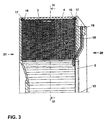
- a tube 18 with a thread 19 is cast into the housing wall 5 on the connection side 20 in the radial direction, which is angled toward the connection side 20 at the end pointing to the central axis 13 of the housing 2.
- This tube serves as a washing device for the compressor wheel, not shown here, and is connected directly to the thread 19 with a line, also not shown, on the connection side 20 of the filter silencer.
- the damping elements 3 are secured with straps 16, which are closed on the circumference of the housing 2 by means of quick-release fasteners 17, against falling out.
- the filter muffler is surrounded on its circumference by an annular filter 4 made of polyurethane foam (PU foam), which filters out particles in the ambient air drawn in.
- the circumference of the annular filter 4 is smaller than the outer circumference of the filter muffler in the unassembled state, so that the filter 4, which is made of PU-elastic rubber, is fixed to the circumference of the muffler by spring force.
- PU foam polyurethan
- damping plate 9 is punched during manufacture in the form of a rectangle from perforated plate with square holes along the perforated webs, and thus has no free-standing webs.
- the rectangular perforated plate is then bent in such a way that a concave surface 12 is formed, to which a convex surface 11 adjoins.
- a flat surface 15 adjoins the convex surface 11 and is bent as a coarse filter segment 15.
- the concave surface 12 and the convex surface 11 run approximately parallel and form an intermediate space 23 into which the absorption element 10, FIG. 5, is inserted.
- An absorption element 10 is thicker than the intermediate space 23, so that when an absorption element 10 is inserted into the intermediate space 23, the surfaces 11, 12 are to be elastically bent apart. After the absorption elements 10 have been inserted into the intermediate space 23, they are clamped between the surfaces 11, 12 on account of their thickness.
- the material used for an absorption element 10 is an open-cell foam which, with the same damping properties, has only about 6% of the specific weight of conventional absorption materials such as wool felt.
- the absorption elements 10 shown in FIG. 5 are cut out rectangularly from foam sheets and are shown here only as bent in their installed state.
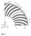
- FIG. 6 shows the arrangement of the damping elements 3, consisting of the damping plate 9 and the absorption element 10, in the circular cylindrical housing 2 with the central axis 13 on the basis of a cross-sectional segment of a filter muffler.
- the damping elements 3 are radially inserted into the grooves 8 and are of the type arranged that their damping surfaces 11, 12 run parallel to the central axis 13 of the housing 2.
- the width of the webs 14, and thus also the cross-sectional area of the air inlet ducts 24 between adjacent damping elements 3, is constant from the outer circumference of the filter muffler to the central axis 13, which ensures a constant speed of the ambient air drawn in. This arrangement reduces compression losses that occur in conventional silencer systems.
- the coarse filter segments 15 of the built-in damping plates 9 are combined to form a coarse filter ring, so that a coarse filter as an individual component is not required.
- An arc-shaped arrangement of the damping elements 3 in the housing 2 extends the air inlet ducts 24, and thus the path of the sound waves, in comparison to purely radial air inlet ducts, as occur in conventional filter silencers with the same outer circumference. This extension of the damping path alone, with the same dimensions as conventional filter silencers, improves sound absorption.
Landscapes
- Engineering & Computer Science (AREA)
- Mechanical Engineering (AREA)
- General Engineering & Computer Science (AREA)
- Chemical & Material Sciences (AREA)
- Combustion & Propulsion (AREA)
- Exhaust Silencers (AREA)
- Structures Of Non-Positive Displacement Pumps (AREA)
- Compressor (AREA)
- Valve Device For Special Equipments (AREA)
- Surgical Instruments (AREA)
- Lubrication Details And Ventilation Of Internal Combustion Engines (AREA)
- Filtering Materials (AREA)
Description
Vorwiegend im Verdichterrad entstehen dabei Schallwellen unerwünscht hoher Amplitude, die durch den Luftansaugkanal an die Umgebung freigesetzt werden. Diese Schallwellen werden daher üblicherweise mittels eines Schalldämpfers gedämpft. Hierfür strömt Umgebungsluft durch ein am Umfang eines Schalldämpfers angeordnetes Filter in den mit Dämpfungselementen ausgestatteten Innenraum des Schalldämpfers, strömt anschliessend an den Dämpfungselementen vorbei, und wird zum Verdichterrad, von dem entgegen der Luftströmung Schallwellen ausgehen, durch Leitelemente umgelenkt. Die Schalldämpfung erfolgt an den Dämpfungselementen dissipativ, indem die Schallenergie unmittelbar durch poröse oder faserige Absorptionsmaterialien, aus denen die Dämpfungselemente im wesentlichen aufgebaut sind, in Wärme umgesetzt wird.
Die oben erwähnte EP 0574605 Al beschreibt einen Filterschalldämpfer, der aus einem gegossenen Monoblock besteht, und in dessen strahlenförmigen Rippen mit Nuten die Dämpfungselemente angeordnet sind. Ein Filterrahmen, bestehend aus einem abnehmbaren Lochblechteil, umgibt den Schalldämpfer in der Art, dass die Dämpfungselemente gegen radiales Herausfallen gesichert werden. Das Lochblechteil ist mittels Verbindungselementen ringförmig um den Schalldämpfer angeordnet.
Ein scheibenförmiges Dämpfungselement besteht aus vier Dämpfungssegmenten, die zusammengesetzt eine Ringfläche darstellen. Ein Absorptionselement wird von zwei gestanzten Lochblechen gehalten, und bildet so ein Dämpfungssegment, das in die Nuten der oben erwähnten Rippen des gegossenen Monoblocks radial eingeführt wird.
Weiterhin ungünstig für die Strömungseigenschaften der Luft wirkt sich die Umlenkung durch Leitelemente an den Dämpfungselemente aus, da durch sie Kompressionsverluste unerwünschter Höhe auftreten.
Das Herabsetzen der Anzahl unterschiedlicher Bauteile ist besonders hinsichtlich des logistischen Aufwandes von Vorteil.
Es zeigen:
- Fig. 1
- einen Teilsegmentschnitt eines Filterschalldämpfers;
- Fig. 2
- eine Ansicht des Filterschalldämpfergehäuses von der Anschlussseite;
- Fig. 3
- einen Teillängsschnitt durch den Filterschalldämpfer;
- Fig. 4
- eine Ansicht eines Dämpfungsblechs;
- Fig. 5
- eine Ansicht einer Anordnung von Absorptionselementen;
- Fig. 6
- einen Teilquerschnitt des Filterschalldämpfers nach der Linie VI-VI gemäss Fig. 3;
Fig. 2 zeigt das als Monoblock aus Aluminium gegossene Gehäuse 2, dessen Gehäusewand 5 auf der Anschlussseite 20 des Filterschalldämpfers mittels Verbindungsstege 7 mit der Gehäusewand 6 auf der Abschlussseite 21 verbunden ist. Auf den Innenseiten der Gehäusewände 5, 6 sind kreisbogenförmige Nuten 8 eingegossen, die zum Innenradius des Filterschalldämpfers hin schmaler verlaufen. Die Querschnittsfläche eines Verbindungsstegs 7 ist in Form und Krümmung einer Nut 8 gleich, und die Verteilung der dreiunddreissig Nuten 8 und der drei Verbindungsstege 7 ist gleichmässig über den Umfang des Gehäuses in einer 10°-Teilung erfolgt.
Zwischen benachbarten Nuten 8 und zwischen Nuten 8 und einem benachbarten Verbindungssteg 7 sind Stege 14 angeordnet, die eine konstante Breite vom Aussenumfang des Gehäuses 2 zum Innenradius in aufweisen.
Auf der Anschlussseite 20 ist ein Anschlussflansch 22 angeordnet, mit dem der Filterschalldämpfer an der Verdichterseite eines hier nicht dargestellten Abgasturboladers montiert wird.
Wie in Fig. 3 gezeigt, ist in die Gehäusewand 5 auf der Anschlussseite 20 in radialer Richtung ein Rohr 18 mit einem Gewinde 19 eingegossen, dass an dem zur Zentralachse 13 des Gehäuses 2 zeigenden Ende zur Anschlussseite 20 abgewinkelt ist. Dieses Rohr dient als Waschvorrichtung für das hier nicht dargestellte Verdichterrad, und wird direkt am Gewinde 19 mit einer ebenfalls nicht dargestellte Leitung auf der Anschlussseite 20 des Filterschalldämpfers verbunden.
Die Dämpfungselemente 3 werden mit Spannbändern 16, die am Umfang des Gehäuses 2 mittels Schnellverschlüssen 17 verschlossen sind, gegen Herausfallen gesichert. Umgeben ist der Filterschalldämpfer an seinem Umfang von einem ringförmigen Filter 4 aus Polyurethanschaum (PU-Schaum), das Partikel in angesaugter Umgebungsluft herausfiltert. Der Kreisumfang des ringförmigen Filters 4 ist im unmontierten Zustand kleiner als der Aussenumfang des Filterschalldämpfers, sodass das Filter 4, welches aus PU-Schaum gummielastisch gefertigt ist, durch Federkraft am Umfang des Schalldämpfers fixiert wird.
Das Dämpfungsblech 9 wird während der Fertigung in Form eines Rechtecks aus Lochblech mit quadratischen Löchern entlang der Lochstege gestanzt, und weist somit keine freistehenden Stege auf. Anschliessend wird das rechteckförmige Lochblech in der Art gebogen, dass sich eine konkave Fläche 12 ausbildet, an die eine konvexe Fläche 11 anschliesst. An die konvexe Fläche 11 schliesst eine ebene Fläche 15 an, die als Grobfiltersegment 15 abgebogen ist. Die konkave Fläche 12 und die konvexe Fläche 11 verlaufen annähernd parallel, und bilden einen Zwischenraum 23 aus, in den das Absorptionselement 10, Fig. 5, eingesetzt wird. Ein Absorptionselement 10 ist dicker, als der Zwischenraum 23, sodass beim Einsetzen eines Absorptionselementes 10 in den Zwischenraum 23 die Flächen 11, 12 elastisch auseinanderzubiegen sind. Nach dem Einsetzten der Absorptionselemente 10 in den Zwischenraum 23, werden diese aufgrund ihrer Dicke zwischen den Flächen 11, 12 eingeklemmt.
Bei dem verwendeten Material für ein Absorptionselement 10 handelt es sich um einen offenzelligen Schaumstoff, der bei gleichen Dämpfungseigenschaften nur etwa 6 % des spezifischen Gewichts herkömmlicher Absorptionsmaterialien wie Wollfilz aufweist. Die in Fig. 5 dargestellten Absorptionselemente 10 werden rechteckförmig aus Schaumstoffplatten ausgeschnitten und sind hier lediglich, wie in ihrem eingebauten Zustand gebogen gezeigt.
Die Breite der Stege 14, und damit auch die Querschnittsfläche der Lufteinlasskanäle 24 zwischen benachbarten Dämpfungselementen 3, ist vom Aussenumfang des Filterschalldämpfers zur Zentralachse 13 hin konstant, wodurch eine konstante Geschwindigkeit angesaugter Umgebungsluft gewährleistet ist. Durch diese Anordnung werden Kompressionsverluste, wie sie bei herkömmlichen Schalldämpfersystemen auftreten, reduziert.
Am Aussenumfang des Gehäuses 2 fügen sich die Grobfiltersegmente 15 der eingebauten Dämpfungsbleche 9 zu einem Grobfilterring zusammen, sodass ein Grobfilter als Einzelbauteil entfällt.
Eine kreisbogenförmige Anordnung der Dämpfungselemente 3 im Gehäuse 2 verlängert die Lufteinlasskanäle 24, und damit den Weg der Schallwellen, im Vergleich zu rein radial verlaufenden Lufteinlasskanälen, wie sie in herkömmlichen Filterschalldämpfern mit gleichem Aussenumfang auftreten. Allein diese Verlängerung des Dämpfungsweges, bei gleichen Abmassen wie herkömmliche Filterschalldämpfer, verbessert die Schalldämpfung.
So ist beispielsweise die Verwendung anderer Dämpfungs- und Filtermaterialien, wie sie oben beschrieben sind, ebenfalls denkbar im Sinn der Erfindung.
- 2
- Gehäuse
- 3
- Dämpfungselement
- 4
- Filter
- 5
- Gehäusewand auf der Anschlussseite
- 6
- Gehäusewand auf der Abschlussseite
- 7
- Verbindungsstege für 5, 6
- 8
- Nuten für 3
- 9
- Dämpfungsblech
- 10
- Absorptionselement
- 11
- konvexe Dämpfungsfläche
- 12
- konkave Dämpfungsfläche
- 13
- Zentralachse
- 14
- Steg zwischen zwei Nuten
- 15
- Grobfiltersegment
- 16
- Spannband
- 17
- Schnellverschluss
- 18
- Rohr
- 19
- Innengewinde in 18
- 20
- Anschlussseite
- 21
- Abschlussseite
- 22
- Anschlussflansch
- 23
- Zwischenraum
- 24
- Lufteinlasskanal
Claims (9)
- Filterschalldämpfer mit einem als Monoblock ausgebildeten Gehäuse (2), in dem mehrere, aus Dämpfungsblechen (9) und Absorptionselementen (10) bestehende Dämpfungselemente (3) angeordnet sind, wobei die Gehäuseform des Filterschalldämpfers eine Zentralachse (13) aufweist,
dadurch gekennzeichnet, dass ein Dämpfungselement (3) aus nur einem Dämpfungsblech (9) besteht, welches nur ein Absorptionselement (10) umschliesst, und
dass die Dämpfungselemente (3) in radialen Nuten (8) der Gehäusewände (5, 6) eines Filterschalldämpfergehäuses (2) angeordnet sind, und dabei die Dämpfungsflächen (11, 12) der Dämpfungselemente (3) parallel zur Zentralachse (13) des Gehäuses orientiert sind. - Filterschalldämpfer nach Anspruch 1,
dadurch gekennzeichnet, dass die Dämpfungselemente (3) und die Nuten (8) im Gehäuse (2) kreisbogenförmig sind. - Filterschalldämpfer nach Anspruch 1,
dadurch gekennzeichnet, dass zwischen benachbarten Dämpfungselementen (3) Lufteinlasskanäle (24) ausgebildet sind, die einen konstanten Querschnitt aufweisen. - Filterschalldämpfer nach Anspruch 1,
dadurch gekennzeichnet, dass das Absorptionselement (10) aus einem Schaumstoff besteht. - Filterschalldämpfer nach Anspruch 1,
dadurch gekennzeichnet, dass an den Dämpfungsblechen (9) Grobfiltersegmente (15) angeordnet sind, die im eingebauten Zustand der Dämpfungselemente (3) in den Nuten (8) ein ringförmiges Grobfilter darstellen. - Filterschalldämpfer nach Anspruch 5,
dadurch gekennzeichnet, dass Spannbänder (16) mit Schnellverschlüssen (17) um das ringförmige Grobfilter aus Grobfiltersegmenten (15) angeordnet sind. - Filterschalldämpfer nach Anspruch 1,
dadurch gekennzeichnet, dass ein ringförmiges Filter (4), bestehend aus PU-Schaum, am Umfang des Filterschalldämpfers angeordnet ist. - Filterschalldämpfer nach Anspruch 1,
dadurch gekennzeichnet, dass das Gehäuse (2) eine kreiszylindrische Form aufweist. - Filterschalldämpfer nach Anspruch 1,
dadurch gekennzeichnet, dass ein Rohr (18) mit Innengewinde (19) auf der Anschlussseite (20) in der Gehäusewand (5) radial angeordnet ist.
Applications Claiming Priority (2)
| Application Number | Priority Date | Filing Date | Title |
|---|---|---|---|
| DE19514990A DE19514990B4 (de) | 1995-04-24 | 1995-04-24 | Filterschalldämpfer |
| DE19514990 | 1995-04-24 |
Publications (3)
| Publication Number | Publication Date |
|---|---|
| EP0740080A2 EP0740080A2 (de) | 1996-10-30 |
| EP0740080A3 EP0740080A3 (de) | 1998-01-07 |
| EP0740080B1 true EP0740080B1 (de) | 2002-09-11 |
Family
ID=7760211
Family Applications (1)
| Application Number | Title | Priority Date | Filing Date |
|---|---|---|---|
| EP96810228A Expired - Lifetime EP0740080B1 (de) | 1995-04-24 | 1996-04-12 | Filterschalldämpfer |
Country Status (9)
| Country | Link |
|---|---|
| US (1) | US5756944A (de) |
| EP (1) | EP0740080B1 (de) |
| JP (1) | JP2781168B2 (de) |
| KR (1) | KR100364891B1 (de) |
| CN (1) | CN1084850C (de) |
| AT (1) | ATE224011T1 (de) |
| CZ (1) | CZ286433B6 (de) |
| DE (2) | DE19514990B4 (de) |
| NO (1) | NO961620L (de) |
Families Citing this family (25)
| Publication number | Priority date | Publication date | Assignee | Title |
|---|---|---|---|---|
| DE19715581C1 (de) * | 1997-04-15 | 1999-02-18 | Weinmann G Geraete Med | Luftzuführung für Gebläse von Geräten zur Beatmung |
| US5861585A (en) * | 1997-09-30 | 1999-01-19 | Aiolos Engineering Corporation | Aeracoustic wind tunnel turning vanes |
| DE29925006U1 (de) * | 1999-09-20 | 2008-04-03 | Fractus, S.A. | Mehrebenenantenne |
| DE10022240A1 (de) * | 2000-05-08 | 2001-11-15 | Abb Turbo Systems Ag Baden | Filterschalldämpfer |
| DE10225092B4 (de) * | 2001-06-08 | 2014-10-09 | Thermamax Hochtemperaturdämmungen GmbH | Schalldämpfer |
| DE10128000C1 (de) * | 2002-06-05 | 2002-11-21 | Thermamax Hochtemperaturdaemmu | Schalldämpfer und Dämpfungselemente dafür |
| US6449947B1 (en) * | 2001-10-17 | 2002-09-17 | Fleetguard, Inc. | Low pressure injection and turbulent mixing in selective catalytic reduction system |
| US6840746B2 (en) * | 2002-07-02 | 2005-01-11 | Bristol Compressors, Inc. | Resistive suction muffler for refrigerant compressors |
| DE10323527B4 (de) * | 2003-05-24 | 2009-04-16 | Danfoss Compressors Gmbh | Kältemittelkompressor |
| WO2005124159A1 (en) * | 2004-06-15 | 2005-12-29 | Honeywell International Inc. | Acoustic damper integrated to a compressor housing |
| DE102006020334B4 (de) * | 2006-04-28 | 2008-07-10 | Man Diesel Se | Filterschalldämpfer |
| US8104572B2 (en) * | 2010-01-22 | 2012-01-31 | Butler Boyd L | Spin muffler |
| DE102010028975A1 (de) | 2010-05-14 | 2012-03-29 | Abb Turbo Systems Ag | Verdichtergehäusezusatz |
| DE102012015907B3 (de) * | 2012-08-10 | 2013-10-17 | Neander Motors Ag | Hubkolbenbrennkraftmaschine, umfassend zumindest einen Hubkolben |
| JP6152612B2 (ja) * | 2012-12-13 | 2017-06-28 | アルパテック株式会社 | 過給機用サイレンサおよびこのサイレンサを使用した過給機 |
| KR102160310B1 (ko) | 2013-03-06 | 2020-09-28 | 에이비비 터보 시스템즈 아게 | 배기가스 터보차저의 소음기 |
| EP2990637B1 (de) * | 2014-09-01 | 2019-01-02 | MANN+HUMMEL GmbH | Schalldämpfer einer Ansauganlage einer Brennkraftmaschine und Ansauganlage |
| CN105484980A (zh) * | 2014-09-19 | 2016-04-13 | 任文华 | 风扇 |
| DE102018100466A1 (de) * | 2018-01-10 | 2019-07-11 | Abb Turbo Systems Ag | Filterschalldämpfer für einen Abgasturbolader einer Brennkraftmaschine |
| DE102018100465A1 (de) * | 2018-01-10 | 2019-07-11 | Abb Turbo Systems Ag | Filterschalldämpfer für einen Abgasturbolader einer Brennkraftmaschine |
| DE102018102237A1 (de) * | 2018-02-01 | 2019-08-01 | Man Energy Solutions Se | Schalldämpfer und Verdichter |
| CN109404345A (zh) * | 2018-12-18 | 2019-03-01 | 南京磁谷科技有限公司 | 一种磁悬浮风机的进风消音结构 |
| DE102019102245A1 (de) | 2019-01-30 | 2020-07-30 | Man Energy Solutions Se | Ansaugschalldämpfer für Turbolader |
| DE102020122027B4 (de) * | 2020-08-24 | 2023-05-04 | Mann+Hummel Gmbh | Schalldämpfer und Filtersystem |
| CN117005970A (zh) * | 2023-07-25 | 2023-11-07 | 中车大连机车研究所有限公司 | 一种分体式便于更换滤芯的增压器空气滤清器 |
Family Cites Families (14)
| Publication number | Priority date | Publication date | Assignee | Title |
|---|---|---|---|---|
| BE533212A (de) * | ||||
| FR985029A (fr) * | 1949-02-16 | 1951-07-13 | Tecalemit | Filtre silencieux d'aspiration |
| DE1290292B (de) * | 1962-06-19 | 1969-03-06 | Maschf Augsburg Nuernberg Ag | Ansaugschalldaempfer fuer Verdichter und Geblaese |
| DE1503270A1 (de) * | 1965-06-24 | 1970-07-16 | Fischachtaler Maschb Gmbh | Einlaufgehaeuse fuer Stroemungsmaschinen |
| DE2305178C2 (de) * | 1973-02-02 | 1982-02-25 | Klöckner-Humboldt-Deutz AG, 5000 Köln | Luftfilter mit Ansauggeräuschdämpfer für eine Brennkraftmaschine |
| DE2354126A1 (de) * | 1973-10-29 | 1975-04-30 | Phonotherm Laerm Und Erschuett | Radialventilator |
| CH603208A5 (de) * | 1975-10-02 | 1978-08-15 | Bbc Brown Boveri & Cie | |
| US4204586A (en) * | 1975-12-11 | 1980-05-27 | Bbc Brown Boveri & Company Limited | Silencer on the intake side of a compressor with assembly of axially spaced annular sound-damping elements |
| CH594139A5 (de) * | 1975-12-11 | 1977-12-30 | Bbc Brown Boveri & Cie | |
| US4316522A (en) * | 1979-11-07 | 1982-02-23 | Industrial Acoustics Company, Inc. | Acoustic filter silencer |
| US4266602A (en) * | 1980-02-21 | 1981-05-12 | Westinghouse Electric Corp. | Heat exchanger for cooling electrical power apparatus |
| DE3506452A1 (de) * | 1985-02-23 | 1986-09-04 | M.A.N.-B & W Diesel GmbH, 8900 Augsburg | Schalldaempfer mit vorleitschaufeln an der ansaugseite des verdichters eines abgasturboladers |
| DE59207544D1 (de) * | 1992-06-17 | 1997-01-02 | Asea Brown Boveri | Filterschalldämpfer |
| CN2191284Y (zh) * | 1994-05-31 | 1995-03-08 | 宋虎男 | 机动车尾气净化消音器 |
-
1995
- 1995-04-24 DE DE19514990A patent/DE19514990B4/de not_active Expired - Lifetime
-
1996
- 1996-03-01 US US08/609,688 patent/US5756944A/en not_active Expired - Lifetime
- 1996-03-27 KR KR1019960008654A patent/KR100364891B1/ko not_active Expired - Lifetime
- 1996-04-12 EP EP96810228A patent/EP0740080B1/de not_active Expired - Lifetime
- 1996-04-12 DE DE59609637T patent/DE59609637D1/de not_active Expired - Lifetime
- 1996-04-12 AT AT96810228T patent/ATE224011T1/de not_active IP Right Cessation
- 1996-04-23 CZ CZ19961171A patent/CZ286433B6/cs not_active IP Right Cessation
- 1996-04-23 NO NO961620A patent/NO961620L/no not_active Application Discontinuation
- 1996-04-24 JP JP8127770A patent/JP2781168B2/ja not_active Expired - Lifetime
- 1996-04-24 CN CN96107306A patent/CN1084850C/zh not_active Expired - Lifetime
Also Published As
| Publication number | Publication date |
|---|---|
| JP2781168B2 (ja) | 1998-07-30 |
| CZ117196A3 (en) | 1996-11-13 |
| JPH08296597A (ja) | 1996-11-12 |
| NO961620D0 (no) | 1996-04-23 |
| US5756944A (en) | 1998-05-26 |
| DE59609637D1 (de) | 2002-10-17 |
| DE19514990B4 (de) | 2005-06-30 |
| EP0740080A2 (de) | 1996-10-30 |
| KR100364891B1 (ko) | 2003-03-15 |
| EP0740080A3 (de) | 1998-01-07 |
| CZ286433B6 (en) | 2000-04-12 |
| CN1084850C (zh) | 2002-05-15 |
| CN1136143A (zh) | 1996-11-20 |
| ATE224011T1 (de) | 2002-09-15 |
| DE19514990A1 (de) | 1996-10-31 |
| NO961620L (no) | 1996-10-25 |
| KR960038143A (ko) | 1996-11-21 |
Similar Documents
| Publication | Publication Date | Title |
|---|---|---|
| DE19514990B4 (de) | Filterschalldämpfer | |
| DE69017042T2 (de) | Doppeltströmungsschalldämpfer für ein turbinentriebwerk. | |
| EP0574605B1 (de) | Filterschalldämpfer | |
| EP2775131B1 (de) | Schalldämpfer eines Abgasturboladers | |
| DE69727502T2 (de) | Schalldämpfer mit trennwänden | |
| DE2907320C2 (de) | Schalldämpfer für die Auspuffleitung einer Brennkraftmaschine | |
| EP0791135B1 (de) | Schalldämpfer | |
| EP1510667B1 (de) | Schalldämpfer | |
| DE102006020334B4 (de) | Filterschalldämpfer | |
| DE10022240A1 (de) | Filterschalldämpfer | |
| EP0806547B1 (de) | Axialturbine eines Abgasturboladers | |
| DE2547523B2 (de) | Brennkraftmaschine mit geräuschdämpfender Verschalung | |
| DE2600860C2 (de) | Schalldämpfer auf der Ansaugseite eines Verdichters mit mehreren Dämpfungselementen | |
| DE69323302T2 (de) | Druckluftschalldämpfer | |
| EP3737846B1 (de) | Filterschalldämpfer für einen abgasturbolader einer brennkraftmaschine | |
| DE7307335U (de) | Abgasschalldaempfer fuer zweitakt- motore | |
| EP4143443A1 (de) | Abgasturbolader mit einem schalldämpfer | |
| DE1403576A1 (de) | Ansaugschalldaempfer | |
| DE3545212C2 (de) | ||
| EP3737850A1 (de) | Filterschalldämpfer für einen abgasturbolader einer brennkraftmaschine | |
| EP2567076A1 (de) | Breitbandig dämpfende vorrichtung zur schalldämpfung bei industrieeinrichtungen, grossanlagen oder maschinen | |
| WO2021254749A1 (de) | Ansaugvorrichtung für einen verdichter | |
| DE2908931A1 (de) | Schalldaempfer | |
| CH404295A (de) | Schalldämpfer | |
| DE29618736U1 (de) | Absorptionsschalldämpfer |
Legal Events
| Date | Code | Title | Description |
|---|---|---|---|
| PUAI | Public reference made under article 153(3) epc to a published international application that has entered the european phase |
Free format text: ORIGINAL CODE: 0009012 |
|
| AK | Designated contracting states |
Kind code of ref document: A2 Designated state(s): AT CH DE DK ES FI FR GB IT LI NL |
|
| RAP1 | Party data changed (applicant data changed or rights of an application transferred) |
Owner name: ASEA BROWN BOVERI AG |
|
| PUAL | Search report despatched |
Free format text: ORIGINAL CODE: 0009013 |
|
| AK | Designated contracting states |
Kind code of ref document: A3 Designated state(s): AT CH DE DK ES FI FR GB IT LI NL |
|
| 17P | Request for examination filed |
Effective date: 19980625 |
|
| RAP1 | Party data changed (applicant data changed or rights of an application transferred) |
Owner name: ABB TURBO SYSTEMS AG |
|
| GRAG | Despatch of communication of intention to grant |
Free format text: ORIGINAL CODE: EPIDOS AGRA |
|
| GRAG | Despatch of communication of intention to grant |
Free format text: ORIGINAL CODE: EPIDOS AGRA |
|
| RTI1 | Title (correction) |
Free format text: FILTER-SILENCER |
|
| RTI1 | Title (correction) |
Free format text: FILTER-SILENCER |
|
| GRAG | Despatch of communication of intention to grant |
Free format text: ORIGINAL CODE: EPIDOS AGRA |
|
| GRAH | Despatch of communication of intention to grant a patent |
Free format text: ORIGINAL CODE: EPIDOS IGRA |
|
| 17Q | First examination report despatched |
Effective date: 20020128 |
|
| RAP1 | Party data changed (applicant data changed or rights of an application transferred) |
Owner name: ABB TURBO SYSTEMS AG |
|
| GRAH | Despatch of communication of intention to grant a patent |
Free format text: ORIGINAL CODE: EPIDOS IGRA |
|
| GRAA | (expected) grant |
Free format text: ORIGINAL CODE: 0009210 |
|
| AK | Designated contracting states |
Kind code of ref document: B1 Designated state(s): AT CH DE DK ES FI FR GB IT LI NL |
|
| PG25 | Lapsed in a contracting state [announced via postgrant information from national office to epo] |
Ref country code: NL Free format text: LAPSE BECAUSE OF FAILURE TO SUBMIT A TRANSLATION OF THE DESCRIPTION OR TO PAY THE FEE WITHIN THE PRESCRIBED TIME-LIMIT Effective date: 20020911 Ref country code: IT Free format text: LAPSE BECAUSE OF FAILURE TO SUBMIT A TRANSLATION OF THE DESCRIPTION OR TO PAY THE FEE WITHIN THE PRESCRIBED TIME-LIMIT;WARNING: LAPSES OF ITALIAN PATENTS WITH EFFECTIVE DATE BEFORE 2007 MAY HAVE OCCURRED AT ANY TIME BEFORE 2007. THE CORRECT EFFECTIVE DATE MAY BE DIFFERENT FROM THE ONE RECORDED. Effective date: 20020911 Ref country code: FI Free format text: LAPSE BECAUSE OF FAILURE TO SUBMIT A TRANSLATION OF THE DESCRIPTION OR TO PAY THE FEE WITHIN THE PRESCRIBED TIME-LIMIT Effective date: 20020911 |
|
| REF | Corresponds to: |
Ref document number: 224011 Country of ref document: AT Date of ref document: 20020915 Kind code of ref document: T |
|
| REG | Reference to a national code |
Ref country code: GB Ref legal event code: FG4D Free format text: NOT ENGLISH |
|
| REG | Reference to a national code |
Ref country code: CH Ref legal event code: EP |
|
| REF | Corresponds to: |
Ref document number: 59609637 Country of ref document: DE Date of ref document: 20021017 |
|
| PG25 | Lapsed in a contracting state [announced via postgrant information from national office to epo] |
Ref country code: DK Free format text: LAPSE BECAUSE OF FAILURE TO SUBMIT A TRANSLATION OF THE DESCRIPTION OR TO PAY THE FEE WITHIN THE PRESCRIBED TIME-LIMIT Effective date: 20021211 |
|
| GBT | Gb: translation of ep patent filed (gb section 77(6)(a)/1977) |
Effective date: 20030107 |
|
| NLV1 | Nl: lapsed or annulled due to failure to fulfill the requirements of art. 29p and 29m of the patents act | ||
| ET | Fr: translation filed | ||
| PG25 | Lapsed in a contracting state [announced via postgrant information from national office to epo] |
Ref country code: ES Free format text: LAPSE BECAUSE OF FAILURE TO SUBMIT A TRANSLATION OF THE DESCRIPTION OR TO PAY THE FEE WITHIN THE PRESCRIBED TIME-LIMIT Effective date: 20030328 |
|
| PG25 | Lapsed in a contracting state [announced via postgrant information from national office to epo] |
Ref country code: AT Free format text: LAPSE BECAUSE OF NON-PAYMENT OF DUE FEES Effective date: 20030412 |
|
| PG25 | Lapsed in a contracting state [announced via postgrant information from national office to epo] |
Ref country code: LI Free format text: LAPSE BECAUSE OF NON-PAYMENT OF DUE FEES Effective date: 20030430 Ref country code: CH Free format text: LAPSE BECAUSE OF NON-PAYMENT OF DUE FEES Effective date: 20030430 |
|
| PLBE | No opposition filed within time limit |
Free format text: ORIGINAL CODE: 0009261 |
|
| STAA | Information on the status of an ep patent application or granted ep patent |
Free format text: STATUS: NO OPPOSITION FILED WITHIN TIME LIMIT |
|
| 26N | No opposition filed |
Effective date: 20030612 |
|
| REG | Reference to a national code |
Ref country code: CH Ref legal event code: PL |
|
| REG | Reference to a national code |
Ref country code: FR Ref legal event code: PLFP Year of fee payment: 20 |
|
| PGFP | Annual fee paid to national office [announced via postgrant information from national office to epo] |
Ref country code: DE Payment date: 20150421 Year of fee payment: 20 Ref country code: GB Payment date: 20150420 Year of fee payment: 20 |
|
| PGFP | Annual fee paid to national office [announced via postgrant information from national office to epo] |
Ref country code: FR Payment date: 20150421 Year of fee payment: 20 |
|
| REG | Reference to a national code |
Ref country code: DE Ref legal event code: R071 Ref document number: 59609637 Country of ref document: DE |
|
| REG | Reference to a national code |
Ref country code: GB Ref legal event code: PE20 Expiry date: 20160411 |
|
| PG25 | Lapsed in a contracting state [announced via postgrant information from national office to epo] |
Ref country code: GB Free format text: LAPSE BECAUSE OF EXPIRATION OF PROTECTION Effective date: 20160411 |