EP0738690B1 - Verfahren und Vorrichtung zum Herstellen eines Stabes aus einem Material mit durchschnittlich einem veränderlichem Gradient - Google Patents
Verfahren und Vorrichtung zum Herstellen eines Stabes aus einem Material mit durchschnittlich einem veränderlichem Gradient Download PDFInfo
- Publication number
- EP0738690B1 EP0738690B1 EP96105559A EP96105559A EP0738690B1 EP 0738690 B1 EP0738690 B1 EP 0738690B1 EP 96105559 A EP96105559 A EP 96105559A EP 96105559 A EP96105559 A EP 96105559A EP 0738690 B1 EP0738690 B1 EP 0738690B1
- Authority
- EP
- European Patent Office
- Prior art keywords
- mold
- tube
- glass
- rod
- casting
- Prior art date
- Legal status (The legal status is an assumption and is not a legal conclusion. Google has not performed a legal analysis and makes no representation as to the accuracy of the status listed.)
- Expired - Lifetime
Links
Images


Classifications
-
- C—CHEMISTRY; METALLURGY
- C03—GLASS; MINERAL OR SLAG WOOL
- C03B—MANUFACTURE, SHAPING, OR SUPPLEMENTARY PROCESSES
- C03B37/00—Manufacture or treatment of flakes, fibres, or filaments from softened glass, minerals, or slags
- C03B37/01—Manufacture of glass fibres or filaments
- C03B37/012—Manufacture of preforms for drawing fibres or filaments
- C03B37/01265—Manufacture of preforms for drawing fibres or filaments starting entirely or partially from molten glass, e.g. by dipping a preform in a melt
- C03B37/01268—Manufacture of preforms for drawing fibres or filaments starting entirely or partially from molten glass, e.g. by dipping a preform in a melt by casting
-
- C—CHEMISTRY; METALLURGY
- C03—GLASS; MINERAL OR SLAG WOOL
- C03B—MANUFACTURE, SHAPING, OR SUPPLEMENTARY PROCESSES
- C03B17/00—Forming molten glass by flowing-out, pushing-out, extruding or drawing downwardly or laterally from forming slits or by overflowing over lips
- C03B17/02—Forming molten glass coated with coloured layers; Forming molten glass of different compositions or layers; Forming molten glass comprising reinforcements or inserts
- C03B17/025—Tubes or rods
-
- C—CHEMISTRY; METALLURGY
- C03—GLASS; MINERAL OR SLAG WOOL
- C03B—MANUFACTURE, SHAPING, OR SUPPLEMENTARY PROCESSES
- C03B37/00—Manufacture or treatment of flakes, fibres, or filaments from softened glass, minerals, or slags
- C03B37/01—Manufacture of glass fibres or filaments
- C03B37/012—Manufacture of preforms for drawing fibres or filaments
- C03B37/01265—Manufacture of preforms for drawing fibres or filaments starting entirely or partially from molten glass, e.g. by dipping a preform in a melt
- C03B37/01274—Manufacture of preforms for drawing fibres or filaments starting entirely or partially from molten glass, e.g. by dipping a preform in a melt by extrusion or drawing
Definitions
- the present invention is related to a procedure and a device for manufacturing a rod of a material presenting a cross-sectional composition gradient and, more particularly, to such a procedure and such a device that make it possible to manufacture a glass rod of which one characteristic, such as the refractive index, the optical density, the ionic conductivity, etc., presents a cross-sectional gradient of a predetermined profile, established by a cross-sectional variation of its composition.
- optical components such as lenses made of a glass that presents an axially symmetric refractive index gradient transversely to the axis of the lens.
- optical fibers that present such an index gradient.
- the composition of the glass is altered transversely to the axis of the component to be obtained by different techniques such as ion exchange (see FR-A-2,504,515), impregnation by the so-called "sol-gel” technique (see US-A-5,069,700), the use of glass compositions starting with powder (US-A-4,883,522), the use of a selectively doped porous glass (US-A-4,620,861), the joining by fusion of glass chips of varied compositions (US-A-4,929,065). if not by other techniques such as the exposure to neutron radiation, the deposition of glass in a vapor phase (in particular, for optical fibers), etc.
- the techniques used heretofore share the application of discontinuous, i.e., batch manufacturing processes, with the discontinuity involving down time which is detrimental from the point of view of productivity of the process and therefore also from the point of view of reducing production costs.
- the known procedures do not allow making, at least economically, components with diameters greater than 1 or 2 cm.
- the index gradients obtained furthermore have proven to be of insufficient amplitude in certain applications and with an insufficiently controlled profile.
- the purpose of the present invention is to provide a procedure and furnish a device that makes it possible to manufacture rods of a material that present a cross-sectional composition gradient and, in particular, glass rods for making optical components with a cross-sectional composition gradient that do not present any of the disadvantages of the known procedures and devices mentioned above.
- JP-A-03-232734 describes a method of manufacturing a rod of a material, which material is in the fluid state at a predetermined temperature above the ambient temperature, the method comprising preparing at least two compositions of this material in the fluid state, simultaneously and concentrically casting one composition to form a core of a rod and casting a second composition to form a sheath around said core, and bringing the casting to a temperature at which the casting solidifies to form the rod.
- a method of manufacturing a rod of a material having a cross-sectional composition gradient, which material is in the fluid state at a predetermined temperature above the ambient temperature comprising:
- a rod is continuously produced from a material such as glass presenting the required cross-sectional composition gradient, with the continuity of the procedure making it possible to obtain high productivity and lower manufacturing costs.
- a material such as glass presenting the required cross-sectional composition gradient
- the continuity of the procedure making it possible to obtain high productivity and lower manufacturing costs.
- the rod is made from two glass compositions of different refractive index, so that the rod presents a cross-sectional refractive index of a predetermined profile.
- the invention also provides a device for implementing the process with this device comprising a) at least two reservoirs, each suitable for receiving one of the two different compositions of the material, in a fluid state, with these two compositions flowing by gravity from these reservoirs through two respective orifices, the one surrounding the other, b) one tube arranged coaxially to these orifices downstream from them to collect their flows, and c) heating and adjustment means to adjust selectively the temperature of the material along its passage in the reservoirs and in the tube.
- the device further comprises, at the tube's outlet, a mold in which the material in a fluid state accumulates, following a laminar flow, with this mold being cylindrical and coaxial to the tube and its cross section greater than that of the tube.
- the composition gradient is obtained by the high-temperature interdiffusion of chemical elements capable of significantly modifying the value of a physical property of the material-of glass, for example, according to their local concentration in the glass.
- the interdiffusion is achieved at least at one interface between two types of glass flowing concentrically in a vertical tube.
- the choice of types of glass is a function of the desired difference in properties and the type of profile required. In the limiting case in which there is no interdiffusion, a discontinuous composition profile is obtained (staggered).
- Two or more types of glasses are melted separately, each in a classical type of furnace (not show), used for the manufacture of types of optical or ophthalmic glass, for example.
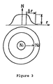
- connection zone 1 The device for implementing the procedure according to the invention, shown in Figure 1, may be divided into three zones, 1, 2, 3, of connection, diffusion and conditioning, respectively.
- the function of the connection zone 1 is to distribute both types of glass between core and skin of a glass rod. It consists of at least two reservoirs 4 and 5 of refractory metal, encased one in the other.
- the position of the interior reservoir 4 is adjustable in order to be able to correct its eccentricity in relation to the exterior reservoir 5.
- Each one of the reservoirs 4 and 5 is fed by the glass coming from one of the melting furnaces.
- the lower end of the exterior reservoir 5 discharges directly into a vertical casting tube 6 and delivers the skin glass.
- the lower end of the interior reservoir 4 consists of a tube 7 that extends several centimeters into the casting tube 6 and delivers the core glass.
- the temperature in the connection zone must be homogeneous and higher than or equal to the temperature of the diffusion zone. It is important to control the temperature at the place where the fluid glasses come into contact and, therefore, to have independent regulation in that zone.
- Annular means of heating 8 are provided to this end, with these means controlled by regulating electronic circuitry 9.
- the diffusion zone 2 is part of the tube 6 in which the diffusion of the chemical elements takes place.
- the depth of interdiffusion is proportional to the square root of the average length of time spent by both types of glass in this part of the tube.
- the temperature is kept constant throughout the zone. Depending on the type of product and the flow rate desired, the length of this zone is generally between 1 and 4 m.
- the conditioning zone 3 serves the dual role of conditioning the glass to the casting temperature and of controlling the flow rate to adjust the temperature profile around the tube.
- the length of this zone may vary from 0.5 to 3 m.
- Heating means 10, 11, controlled by the electronics 9 make it possible to adjust the temperature in zones 2 and 3.
- the dimensions of the casting tube 6 are such that they establish stable casting of the two types of glass in the diffusion zone.
- the stability depends essentially on the difference in density and viscosity between both fluids. It has been found experimentally that the casting should satisfy the following stability criteria: gR 2 ( ⁇ max - ⁇ min ) u ⁇ (preferably ⁇ 10) 1 ⁇ ⁇ max ⁇ min ⁇ 2 with:
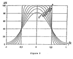
- the index profile obtained corresponds to the "S" diffusion profile, with an inflection point in the vicinity of the initial interface between the two types of glass. Trials at 1,400° have made it possible to verify that this type of profile is certainly obtained.
- the two parameters that make it possible to modify the shape of the profile are length of diffusion time (time spent in the tube) and the position of the interface.
- Figure 3 shows an index profile N as a function of the radius r.
- a glass rod with a large diameter is formed by making the doughy glass casting leaving the pipe 6 go into a cylindrical mold shaped to define the final section of the rod. Lenses of a great diameter, for example, can then be formed from blanks cut from this rod.
- the procedure according to the invention makes it possible to transfer homothetically the composition profile (diffused profile or simultaneous casting of two types of glass) obtained at the bottom of the tube to the rod. the diameter of which is determined by the mold.
- the ratio of the diameter of this rod to the interior diameter of the tube 6 is within a broad range (1:1 to 100:1 and preferably from 1.4:1 to 36:1).
- the advantage of this is:
- Figure 4 shows a first way of using a mold for the broadening of the glass casting.
- This flow is done in a laminar fashion and without a recirculation zone, which makes it possible to transfer homothetically the glass composition profile transfer.
- the glass flows continuously in the mold.
- This mold is equipped with means for adjusting the temperature, which makes it possible to master the rate at which the glass cools.
- the length of the mold is chosen so that, when the glass leaves the mold, it has reached a high enough viscosity to support its own weight and to be able to be gripped in one or several sets of suitably profiled rollers 15 1 , 15 2 , without undergoing deformations or surface damage.
- the role of these rollers is to support the weight of glass contained in the mold and to regulate its speed in order to keep the spreading zone of the glass at a stable rate and at a considerably constant height.
- the mold may comprise a movable bottom (not shown) such as that (17) of the mold shown in Figure 5, which will be examined in further detail, which bottom causes the casting to broaden.
- the bottom descends within the mold and is withdrawn after having passed between the rollers 15 1 , 15 2 .
- thermal conditioning zone comprising adjustment means (cooling and/or heating) with a view to providing additional cooling of the glass and homogenization of the core/skin temperatures before cutting the rods into the desired dimensions.
- This conditioning zone may comprise one or several sets of rollers.
- the mold 16 is equipped with a movable bottom 17 actuated, for example, by a gear motor that drives a screw jack.
- the mold is first presented with its movable bottom 16 in a high position within the casting tube 6, and the bottom is continuously displaced downward.
- the movable bottom 17 is returned to its high position to release the glass from the mold.
- a shearing device may be used to interrupt the glass fiber flowing from the tube.
- the rate at which the movable bottom 17 descends is a function of the flow rate of the tube 6, as in the preceding embodiment, so as to prevent any turbulent flow of the glass into the mold, likely to disturb the radial composition gradient established in the tube.
- the molds are equipped with means for adjusting the temperature.
- a high temperature in the high zone of the mold is sought in order to limit the cooling of the glass in the spreading zone, with this becoming more necessary as the ratio of the mold diameter to the tube diameter increases.
- Lower temperatures will be sought in the lower parts of the mold in order to cool the glass.
- the mold may be made of traditional materials, for example, metal materials, such as stainless steel, bronze or graphite, the latter being preferred.
- metal materials such as stainless steel, bronze or graphite, the latter being preferred.
- the temperatures are limited to prevent the appearance of sticking phenomena between the mold and the glass (temperatures on the order of 550° C for a soda lime glass).
- the temperatures may be lowered down to 400-450°C.
- Another disadvantage is that the sliding of the glass may not be completely regular, when the temperature profile of the mold is not optimum, which may, in certain cases, disturb the transfer of the profile of the glass composition.
- a mold 18, shown as a diagram in Figure 5 may be used, consisting of a wall 19 made of a porous material (for example, graphite, porous bronze or stainless, or ceramic).
- Rollers 20 1 , 20 2 regulate the downward speed of the glass rod through the mold as in the embodiment in Figure 4.
- a gas cushion is thus formed between the inside the mold and the glass rod, which provides the following advantages: (a) high freedom of choice of temperature in the upper zone of the mold, not limited by risks of sticking. A high spreading ratio may thus be obtained, and chill wrinkles can be eliminated, and (b) the absence of contact between the glass and the mold makes resistance-free and therefore regular downward movement possible and, thus, an excellent profile-transferring quality.
- the porous mold may also be equipped with thermal control means by air or water cooling, or by electric heating or burner.
- a device 21 designed to reduce heat losses below the tube, within the spreading zone (see Figure 4).
- a device provides electric heating or heating with a burner. It may also be mechanically linked to the mold.
- composition profile 20 ⁇ G ⁇ 100% 0 ⁇ G ⁇ 20% Flow rate 1-30 kg/h 1-500 kg/h Diffusion temperature 1100-1500°C 1100-1500°C Low tube viscosity 50-10,000 P (preferably 200 to 5,000 P) 50-10,000 P Tube diameter 10-50 mm 10-50 mm Mold diameter 10-100 mm 10-150 mm ⁇ mold 1-10 1-10 ⁇ tube
- L ref + L cond corresponds to the length of the conditioning zone 3 located in Figure 1.
- the invention is not limited to the embodiments described and shown, which have only been given by way of example. It is thus that, although the examples described illustrate the obtention of refractive index gradient in the glass, the invention may as well be implemented so as to establish an optical density gradient (obtention of colored glass, possibly photochromic glass, for example) or an ionic conductivity gradient, for example.
- Composition gradients may also be established in materials other than glass or glass ceramics, suitable for interdiffusing in the fluid state.
- the device according to the invention may comprise more than two concentric reservoirs in order to fine tune still more the control of the composition profile to be implemented.
- the mold may still present an other than circular section, for example, square or rectangular, without sharp angles for making glass rods with such a section. Moreover, it may present an orientation other than vertical, although this may be preferred in order to obtain perfectly axially symmetric gradients.
Landscapes
- Chemical & Material Sciences (AREA)
- Engineering & Computer Science (AREA)
- Materials Engineering (AREA)
- Organic Chemistry (AREA)
- Life Sciences & Earth Sciences (AREA)
- General Life Sciences & Earth Sciences (AREA)
- Geochemistry & Mineralogy (AREA)
- Manufacturing & Machinery (AREA)
- Glass Compositions (AREA)
- Manufacture, Treatment Of Glass Fibers (AREA)
- Casting Or Compression Moulding Of Plastics Or The Like (AREA)
- Crystals, And After-Treatments Of Crystals (AREA)
Claims (16)
- Verfahren zur Herstellung eines Stabs aus einem Material, das im Querschnitt einen Gradienten der Zusammensetzung aufweist, wobei das Material bei einer vorbestimmten Temperatur oberhalb der Umgebungstemperatur im fluiden Zustand ist, mit den Schritten:a) Bereitstellen von mindestens zwei Zusammensetzungen dieses Materials im fluiden Zustand;b) gleichzeitiges und konzentrisches Giessen einer Zusammensetzung, um einen Kern eines Stabs zu bilden und einer zweiten Zusammensetzung, um eine Hülle um den Kern zu bilden, undc) thermische Interdiffusion der Kern- und Hüllzusammensetzungen über ihre Grenzfläche; undd) Bewirken der Vergrößerung eines Bereichs des Gusses, indem dieser durch eine zylindrische Form (14, 16, 18) geführt wird, die so geformt ist, dass ein Endbereich des Stabs definiert wird; unde) den Guss auf eine Temperatur bringen, bei der sich der Guß verfestigt, um den Stab zu bilden.
- Verfahren nach Anspruch 1, wobei die Position der Grenzfläche eingestellt wird, indem das Verhältnis der Flußraten der Zusammensetzungen reguliert wird.
- Verfahren nach Anspruch 1 oder 2, wobei der Guß in einem Verhältnis von 1:1 bis 1:100 vergrößert wird.
- Verfahren nach Anspruch 3, wobei das Verhältnis 1:1,4 bis 1:36 ist.
- Verfahren nach Anspruch 4, wobei die Form (18) eine poröse Wand (19) aufweist, durch die ein Gasstrom in die Form eintritt.
- Verfahren nach einem der vorhergehenden Ansprüche, wobei die zwei Zusammensetzungen sich im Brechungsindex unterscheiden, so daß der gebildete Stab ein vorbestimmtes Querschnitts-Brechungsindexprofil aufweist.
- Vorrichtung zur Herstellung eines Stabs aus einem Material, das im Querschnitt einen Gradienten der Zusammensetzung aufweist, mit:a) mindestens zwei Reservoiren (4, 5), die beide eine Öffnung aufweisen, so dass eine Öffnung von der anderen umgeben ist, und jedes Reservoir geeignet ist, eines der mindestens zwei verschiedenen Zusammensetzungen des Materials in einem fluiden Zustand aufzunehmen, wobei die Zusammensetzungen aufgrund der Schwerkraft von diesen Reservoiren durch die jeweiligen Öffnungen fließen;b) einem Rohr (6), das abwärts und koaxial zu diesen Öffnungen angeordnet ist, um das hierdurch fließende Material aufzunehmen; undc) Heiz- und Einstelleinrichtungen (8, 10, 11), um selektiv die Temperatur des Materials entlang seines Durchgangs in den Reservoiren und in dem Rohr einzustellen; undd) einer Form (14, 16, 18), die mit dem Auslass des Rohrs (6) verbunden ist, in der das Material nach einer Laminarbewegung in einem fluiden Zustand anfällt, wobei diese Form zylindrisch und koaxial zu dem Rohr ist und deren Querschnitt größer als der des Rohrs ist.
- Vorrichtung nach Anspruch 7, die weiterhin eine Einrichtung (3) zur Einstellung des Flusses der Zusammensetzungen in dem Rohr aufweist.
- Vorrichtung nach Anspruch 7 und 8, wobei die Oberflächen der Querschnitte der Form (14, 16, 18) und des Rohrs (6) einVerhältnis von 1:1 bis 1:100 aufweisen.
- Vorrichtung nach Anspruch 9, wobei das Verhältnis 1:1,4 bis 1:36 beträgt.
- Vorrichtung nach einem der Ansprüche 7 bis 9, wobei die Form (16) eine bewegliche Unterseite (17) aufweist und eine Einrichtung, um diese Unterseite zwischen dem oberen und unteren Teil der Form zu verschieben, wobei sich die Unterseite abwärts bewegt, wenn die Form mit dem aus dem Rohr (6) fließenden Material gefüllt wird.
- Vorrichtung nach einem der Ansprüche 7 bis 10, wobei die Unterseite der Form offen ist.
- Vorrichtung nach einem der Ansprüche 7 bis 12, die Führungsrollen (15, 20) aufweist, die abwärts der Unterseite der Vorrichtung angeordnet sind, um die Vorrückgeschwindigkeit des Materials einzustellen, wenn dieses aus der Vorrichtung tritt.
- Vorrichtung nach einem der Ansprüche 7 bis 13, die mehrere identische Formen aufweist, die auf einer Dreheinrichtung (turret) sitzen und einer Einrichtung, um jede Form sukzessiv unter dem Ende des Rohrs (6) anzuordnen, bis sie mit dem Material gefüllt ist.
- Vorrichtung nach einem der Ansprüche 7 bis 14, wobei die Wände (19) der Form (18) porös sind und Einrichtungen vorgesehen sind, um ein Gas durch diese Wände zum Inneren der Form zu blasen, um ein Gaskissen zwischen der innenseitigen Wand der Form und dem darin befindlichen Material auszubilden.
- Verwendung des Verfahrens nach einem der Ansprüche 7 bis 15 zur Herstellung von Glasstäben mit einem Querschnitts-Brechungsindexgradienten eines vorbestimmten Profils oder mit einem Querschnitts-Gradienten der optischen Dichte.
Applications Claiming Priority (4)
| Application Number | Priority Date | Filing Date | Title |
|---|---|---|---|
| US4515 | 1987-01-20 | ||
| FR9504646 | 1995-04-19 | ||
| FR9504646A FR2733224B1 (fr) | 1995-04-19 | 1995-04-19 | Procede et dispositif de fabrication d'une barre en un materiau presentant un gradient de composition transversal, notamment de barre de verre |
| US451595P | 1995-09-29 | 1995-09-29 |
Publications (2)
| Publication Number | Publication Date |
|---|---|
| EP0738690A1 EP0738690A1 (de) | 1996-10-23 |
| EP0738690B1 true EP0738690B1 (de) | 2001-06-13 |
Family
ID=26231899
Family Applications (1)
| Application Number | Title | Priority Date | Filing Date |
|---|---|---|---|
| EP96105559A Expired - Lifetime EP0738690B1 (de) | 1995-04-19 | 1996-04-09 | Verfahren und Vorrichtung zum Herstellen eines Stabes aus einem Material mit durchschnittlich einem veränderlichem Gradient |
Country Status (5)
| Country | Link |
|---|---|
| US (1) | US6062047A (de) |
| EP (1) | EP0738690B1 (de) |
| JP (1) | JPH09110455A (de) |
| DE (1) | DE69613270T2 (de) |
| ES (1) | ES2159656T3 (de) |
Families Citing this family (10)
| Publication number | Priority date | Publication date | Assignee | Title |
|---|---|---|---|---|
| EP1184339A3 (de) * | 2000-09-01 | 2002-09-04 | A.R.T.-Photonics GmbH | Optische Faser und Herstellungsverfahren für eine optische Faser |
| US6598429B1 (en) | 2000-11-17 | 2003-07-29 | Beamtek, Inc. | Method for fabricating gradient-index rods and rod arrays |
| JP2005503008A (ja) * | 2001-09-10 | 2005-01-27 | カール−ツァイス−シュティフトゥング | 少なくとも2層のガラスクラッドを有するガラスファイバ |
| US6526782B1 (en) * | 2001-09-28 | 2003-03-04 | The United States Of America As Represented By The Secretary Of The Navy | Multi heating zone apparatus and process for making core/clad glass fibers |
| DE10157258B4 (de) * | 2001-11-22 | 2006-11-30 | Schott Ag | Verfahren und Vorrichtung zum Ausformen eines rohrförmigen Gegenstandes aus thermoplastischen Materialien |
| JP2003326546A (ja) * | 2002-05-10 | 2003-11-19 | Konica Minolta Holdings Inc | 成形装置及び成形方法 |
| US20040118155A1 (en) * | 2002-12-20 | 2004-06-24 | Brown John T | Method of making ultra-dry, Cl-free and F-doped high purity fused silica |
| DE102005058452A1 (de) * | 2005-12-07 | 2007-06-21 | Linde Ag | Bubblerstein |
| CN101028964B (zh) * | 2007-02-08 | 2010-11-17 | 河南安彩高科股份有限公司 | 控制玻璃板厚度均匀性的装置及其控制方法 |
| EP2364956A1 (de) * | 2010-02-25 | 2011-09-14 | Corning Incorporated | Verfahren zur Stabilisierung einer Säule aus geschmolzenem Material |
Family Cites Families (19)
| Publication number | Priority date | Publication date | Assignee | Title |
|---|---|---|---|---|
| US3298808A (en) * | 1965-05-11 | 1967-01-17 | Macks Elmer Fred | Concentric foraminous shaping means for tubes or bars |
| US3614197A (en) * | 1967-04-27 | 1971-10-19 | Semiconductor Res Found | Solid optical wave guide having a radially varying refractive index |
| US4023953A (en) * | 1975-08-07 | 1977-05-17 | Corning Glass Works | Apparatus and method for producing composite glass tubing |
| JPS5393847A (en) * | 1977-01-27 | 1978-08-17 | Nippon Sheet Glass Co Ltd | Production method of light fiber |
| EP0004183B1 (de) * | 1978-03-14 | 1981-09-16 | The Post Office | Verfahren und Vorrichtung zum Ziehen von optischen Fasern mittels eines doppelten Schmelztiegels |
| US4248614A (en) * | 1979-03-19 | 1981-02-03 | Corning Glass Works | Method for drawing high-bandwidth optical waveguides |
| FR2504515A1 (fr) * | 1981-04-27 | 1982-10-29 | Essilor Int | Procede pour l'obtention d'un verre mineral a gradient d'indice, et article, en particulier lentille ophtalmique, en un tel verre |
| US4383843A (en) * | 1981-09-16 | 1983-05-17 | Western Electric Company, Inc. | Methods of and apparatus for heating a preform from which lightguide fiber is drawn |
| NL8204438A (nl) * | 1982-11-16 | 1984-06-18 | Philips Nv | Werkwijze en inrichting voor de continue vervaardiging van langgerekte lichamen uitgaande van een ongesmolten uitgangsmateriaal. |
| JPS60176938A (ja) * | 1984-02-24 | 1985-09-11 | Nippon Telegr & Teleph Corp <Ntt> | 光フアイバ用プリフオ−ムの製造方法 |
| IT1179876B (it) * | 1984-12-18 | 1987-09-16 | Cselt Centro Studi Lab Telecom | Apparecchiatura per la produzione continua di fibre ottiche |
| JPS6246934A (ja) * | 1985-08-22 | 1987-02-28 | Kokusai Denshin Denwa Co Ltd <Kdd> | フツ化物ガラスフアイバ用母材の製造方法及び装置 |
| US4620861A (en) * | 1985-11-04 | 1986-11-04 | Corning Glass Works | Method for making index-profiled optical device |
| US4883522A (en) * | 1987-08-19 | 1989-11-28 | Integrated Solar Technologies Corp. | Fabrication of macro-gradient optical density transmissive light concentrators, lenses and compound lenses of large geometry |
| US4929065A (en) * | 1988-11-03 | 1990-05-29 | Isotec Partners, Ltd. | Glass plate fusion for macro-gradient refractive index materials |
| JP2562705B2 (ja) * | 1990-02-08 | 1996-12-11 | 国際電信電話株式会社 | フッ化物ガラスファイバ用母材の製造方法及び装置 |
| JPH068179B2 (ja) * | 1990-04-12 | 1994-02-02 | 東京工業大学長 | 屈折率分布ガラスの製造方法 |
| FR2686597B1 (fr) * | 1992-01-28 | 1994-03-18 | Alcatel Nv | Procede de fabrication d'un tube en verre, notamment en verre fluore. |
| DE4212099C2 (de) * | 1992-04-10 | 1994-07-21 | Heraeus Quarzglas | Verfahren und Vorrichtung zur Herstellung eines Verbundkörpers aus Glas |
-
1996
- 1996-04-09 EP EP96105559A patent/EP0738690B1/de not_active Expired - Lifetime
- 1996-04-09 ES ES96105559T patent/ES2159656T3/es not_active Expired - Lifetime
- 1996-04-09 DE DE69613270T patent/DE69613270T2/de not_active Expired - Fee Related
- 1996-04-10 US US08/630,652 patent/US6062047A/en not_active Expired - Lifetime
- 1996-04-19 JP JP8098190A patent/JPH09110455A/ja active Pending
Also Published As
| Publication number | Publication date |
|---|---|
| ES2159656T3 (es) | 2001-10-16 |
| DE69613270D1 (de) | 2001-07-19 |
| EP0738690A1 (de) | 1996-10-23 |
| US6062047A (en) | 2000-05-16 |
| DE69613270T2 (de) | 2002-05-16 |
| JPH09110455A (ja) | 1997-04-28 |
Similar Documents
| Publication | Publication Date | Title |
|---|---|---|
| US4145200A (en) | Production of optical glass fibers | |
| EP0738690B1 (de) | Verfahren und Vorrichtung zum Herstellen eines Stabes aus einem Material mit durchschnittlich einem veränderlichem Gradient | |
| US4897100A (en) | Apparatus and process for fiberizing fluoride glasses using a double crucible and the compositions produced thereby | |
| CN101792249B (zh) | 玻璃成形体的制备方法和光学元件的制备方法 | |
| US5683482A (en) | Device and method for shaping rods, especially of glassy material | |
| EP3587364B1 (de) | Kontinuierliches verfahren zur herstellung eines glasbandes | |
| JPH0624785A (ja) | ガラス製の複合材料を製造する方法および装置 | |
| CN105060700B (zh) | 软玻璃光纤预制棒制作装置及方法 | |
| US5106400A (en) | Casting core/clad glass preforms method and apparatus | |
| US4351659A (en) | Method for manufacture of graded index optical fibres | |
| JP2007533579A (ja) | 管又は棒を製造する装置及び方法 | |
| US6499316B2 (en) | Method of producing a glass gob, method of producing a glass molded product, and apparatus for producing a glass gob | |
| US5308371A (en) | Method of forming fluoride glass fiber preform | |
| DE102004034797B4 (de) | Verfahren zur Herstellung feuerpolierter Gobs | |
| JP4162562B2 (ja) | ガラス成形体の製造方法、プレス成形用ガラス素材の製造方法、および光学素子の製造方法 | |
| TWI414498B (zh) | 噴嘴以及使用該噴嘴製造光學玻璃塊之方法 | |
| JP5438084B2 (ja) | ガラス成形体の製造方法、及び、そのガラス成形体を用いる光学素子の製造方法 | |
| JP4445345B2 (ja) | ガラス成形体、プレス成形用ガラス素材、光学素子、ガラス基板それぞれの製造方法 | |
| JP2562705B2 (ja) | フッ化物ガラスファイバ用母材の製造方法及び装置 | |
| EP4001229A2 (de) | Vorrichtung und verfahren zur walzformung von glasscheiben mit hohem brechungsindex | |
| JP4408828B2 (ja) | ガラス流出パイプ、ガラス成形体の製造方法および光学素子の製造方法 | |
| KR101252314B1 (ko) | 유리 유출 파이프, 유리 제조 장치, 유리 성형체의 제조방법, 및 광학 소자의 제조 방법 | |
| JPS62270431A (ja) | 光フアイバ用母材の製造方法およびその製造装置 | |
| FR2733224A1 (fr) | Procede et dispositif de fabrication d'une barre en un materiau presentant un gradient de composition transversal, notamment de barre de verre | |
| JP2000119026A (ja) | ガラスゴブの製造方法 |
Legal Events
| Date | Code | Title | Description |
|---|---|---|---|
| PUAI | Public reference made under article 153(3) epc to a published international application that has entered the european phase |
Free format text: ORIGINAL CODE: 0009012 |
|
| AK | Designated contracting states |
Kind code of ref document: A1 Designated state(s): DE ES GB |
|
| 17P | Request for examination filed |
Effective date: 19970326 |
|
| 17Q | First examination report despatched |
Effective date: 19990625 |
|
| GRAG | Despatch of communication of intention to grant |
Free format text: ORIGINAL CODE: EPIDOS AGRA |
|
| GRAG | Despatch of communication of intention to grant |
Free format text: ORIGINAL CODE: EPIDOS AGRA |
|
| GRAH | Despatch of communication of intention to grant a patent |
Free format text: ORIGINAL CODE: EPIDOS IGRA |
|
| GRAH | Despatch of communication of intention to grant a patent |
Free format text: ORIGINAL CODE: EPIDOS IGRA |
|
| GRAA | (expected) grant |
Free format text: ORIGINAL CODE: 0009210 |
|
| AK | Designated contracting states |
Kind code of ref document: B1 Designated state(s): DE ES GB |
|
| REF | Corresponds to: |
Ref document number: 69613270 Country of ref document: DE Date of ref document: 20010719 |
|
| REG | Reference to a national code |
Ref country code: ES Ref legal event code: FG2A Ref document number: 2159656 Country of ref document: ES Kind code of ref document: T3 |
|
| REG | Reference to a national code |
Ref country code: GB Ref legal event code: IF02 |
|
| PLBE | No opposition filed within time limit |
Free format text: ORIGINAL CODE: 0009261 |
|
| STAA | Information on the status of an ep patent application or granted ep patent |
Free format text: STATUS: NO OPPOSITION FILED WITHIN TIME LIMIT |
|
| 26N | No opposition filed | ||
| PGFP | Annual fee paid to national office [announced via postgrant information from national office to epo] |
Ref country code: GB Payment date: 20030313 Year of fee payment: 8 |
|
| PGFP | Annual fee paid to national office [announced via postgrant information from national office to epo] |
Ref country code: ES Payment date: 20030425 Year of fee payment: 8 |
|
| PGFP | Annual fee paid to national office [announced via postgrant information from national office to epo] |
Ref country code: DE Payment date: 20030430 Year of fee payment: 8 |
|
| PG25 | Lapsed in a contracting state [announced via postgrant information from national office to epo] |
Ref country code: GB Free format text: LAPSE BECAUSE OF NON-PAYMENT OF DUE FEES Effective date: 20040409 |
|
| PG25 | Lapsed in a contracting state [announced via postgrant information from national office to epo] |
Ref country code: ES Free format text: LAPSE BECAUSE OF NON-PAYMENT OF DUE FEES Effective date: 20040410 |
|
| PG25 | Lapsed in a contracting state [announced via postgrant information from national office to epo] |
Ref country code: DE Free format text: LAPSE BECAUSE OF NON-PAYMENT OF DUE FEES Effective date: 20041103 |
|
| GBPC | Gb: european patent ceased through non-payment of renewal fee |
Effective date: 20040409 |
|
| REG | Reference to a national code |
Ref country code: ES Ref legal event code: FD2A Effective date: 20040410 |