EP0737937A2 - Bildverarbeitungsgerät - Google Patents
Bildverarbeitungsgerät Download PDFInfo
- Publication number
- EP0737937A2 EP0737937A2 EP96110758A EP96110758A EP0737937A2 EP 0737937 A2 EP0737937 A2 EP 0737937A2 EP 96110758 A EP96110758 A EP 96110758A EP 96110758 A EP96110758 A EP 96110758A EP 0737937 A2 EP0737937 A2 EP 0737937A2
- Authority
- EP
- European Patent Office
- Prior art keywords
- data
- pictorial image
- display
- main memory
- line
- Prior art date
- Legal status (The legal status is an assumption and is not a legal conclusion. Google has not performed a legal analysis and makes no representation as to the accuracy of the status listed.)
- Granted
Links
Images


Classifications
-
- G—PHYSICS
- G09—EDUCATION; CRYPTOGRAPHY; DISPLAY; ADVERTISING; SEALS
- G09G—ARRANGEMENTS OR CIRCUITS FOR CONTROL OF INDICATING DEVICES USING STATIC MEANS TO PRESENT VARIABLE INFORMATION
- G09G5/00—Control arrangements or circuits for visual indicators common to cathode-ray tube indicators and other visual indicators
- G09G5/36—Control arrangements or circuits for visual indicators common to cathode-ray tube indicators and other visual indicators characterised by the display of a graphic pattern, e.g. using an all-points-addressable [APA] memory
- G09G5/363—Graphics controllers
- G09G5/366—Graphics controllers with conversion of CRT control signals to flat panel control signals, e.g. adapting the palette memory
-
- G—PHYSICS
- G06—COMPUTING; CALCULATING OR COUNTING
- G06K—GRAPHICAL DATA READING; PRESENTATION OF DATA; RECORD CARRIERS; HANDLING RECORD CARRIERS
- G06K15/00—Arrangements for producing a permanent visual presentation of the output data, e.g. computer output printers
- G06K15/02—Arrangements for producing a permanent visual presentation of the output data, e.g. computer output printers using printers
-
- G—PHYSICS
- G06—COMPUTING; CALCULATING OR COUNTING
- G06T—IMAGE DATA PROCESSING OR GENERATION, IN GENERAL
- G06T11/00—2D [Two Dimensional] image generation
- G06T11/001—Texturing; Colouring; Generation of texture or colour
-
- G—PHYSICS
- G06—COMPUTING; CALCULATING OR COUNTING
- G06T—IMAGE DATA PROCESSING OR GENERATION, IN GENERAL
- G06T3/00—Geometric image transformation in the plane of the image
- G06T3/40—Scaling the whole image or part thereof
-
- G—PHYSICS
- G09—EDUCATION; CRYPTOGRAPHY; DISPLAY; ADVERTISING; SEALS
- G09G—ARRANGEMENTS OR CIRCUITS FOR CONTROL OF INDICATING DEVICES USING STATIC MEANS TO PRESENT VARIABLE INFORMATION
- G09G1/00—Control arrangements or circuits, of interest only in connection with cathode-ray tube indicators; General aspects or details, e.g. selection emphasis on particular characters, dashed line or dotted line generation; Preprocessing of data
- G09G1/28—Control arrangements or circuits, of interest only in connection with cathode-ray tube indicators; General aspects or details, e.g. selection emphasis on particular characters, dashed line or dotted line generation; Preprocessing of data using colour tubes
-
- H—ELECTRICITY
- H04—ELECTRIC COMMUNICATION TECHNIQUE
- H04N—PICTORIAL COMMUNICATION, e.g. TELEVISION
- H04N1/00—Scanning, transmission or reproduction of documents or the like, e.g. facsimile transmission; Details thereof
- H04N1/46—Colour picture communication systems
- H04N1/56—Processing of colour picture signals
- H04N1/60—Colour correction or control
- H04N1/62—Retouching, i.e. modification of isolated colours only or in isolated picture areas only
- H04N1/622—Retouching, i.e. modification of isolated colours only or in isolated picture areas only with simulation on a subsidiary picture reproducer
-
- H—ELECTRICITY
- H04—ELECTRIC COMMUNICATION TECHNIQUE
- H04N—PICTORIAL COMMUNICATION, e.g. TELEVISION
- H04N1/00—Scanning, transmission or reproduction of documents or the like, e.g. facsimile transmission; Details thereof
- H04N1/46—Colour picture communication systems
- H04N1/64—Systems for the transmission or the storage of the colour picture signal; Details therefor, e.g. coding or decoding means therefor
-
- G—PHYSICS
- G06—COMPUTING; CALCULATING OR COUNTING
- G06K—GRAPHICAL DATA READING; PRESENTATION OF DATA; RECORD CARRIERS; HANDLING RECORD CARRIERS
- G06K2215/00—Arrangements for producing a permanent visual presentation of the output data
- G06K2215/0002—Handling the output data
- G06K2215/004—Generic data transformation
- G06K2215/0042—Rasterisation
- G06K2215/0051—Rasterisation from compressed bitmap, e.g. run length
-
- G—PHYSICS
- G06—COMPUTING; CALCULATING OR COUNTING
- G06K—GRAPHICAL DATA READING; PRESENTATION OF DATA; RECORD CARRIERS; HANDLING RECORD CARRIERS
- G06K2215/00—Arrangements for producing a permanent visual presentation of the output data
- G06K2215/0082—Architecture adapted for a particular function
- G06K2215/0094—Colour printing
-
- G—PHYSICS
- G09—EDUCATION; CRYPTOGRAPHY; DISPLAY; ADVERTISING; SEALS
- G09G—ARRANGEMENTS OR CIRCUITS FOR CONTROL OF INDICATING DEVICES USING STATIC MEANS TO PRESENT VARIABLE INFORMATION
- G09G2340/00—Aspects of display data processing
- G09G2340/02—Handling of images in compressed format, e.g. JPEG, MPEG
-
- G—PHYSICS
- G09—EDUCATION; CRYPTOGRAPHY; DISPLAY; ADVERTISING; SEALS
- G09G—ARRANGEMENTS OR CIRCUITS FOR CONTROL OF INDICATING DEVICES USING STATIC MEANS TO PRESENT VARIABLE INFORMATION
- G09G5/00—Control arrangements or circuits for visual indicators common to cathode-ray tube indicators and other visual indicators
- G09G5/02—Control arrangements or circuits for visual indicators common to cathode-ray tube indicators and other visual indicators characterised by the way in which colour is displayed
Definitions
- This invention relates to a pictorial image processing system utilizing a computer, and more particularly to a technology for processing pictorial image data on a memory and handling the processed data. Especially, this invention is concerned with a pictorial image processing system suitable for processing a pictorial image in a screen tint portion of a printed matter.
- screen tint portions a large of portions having a fixed color tone, so called screen tint portions, exist in color printed matters.
- the prepress process of such screen tint portions are carried out by a special process different from the prepress process of general color portions. Colors represented by a mixture of four colors of yellow (Y), magenta (M), cyan (C) and black (K) are given to respective screen tint portions. Such mixed colors are determined by numeric values expressed by dot percent rates (hereinafter called dot percent) in color separation used for respective colors at the time of printing.
- the above-described apparatus for preparing a screen tint film using a computer typically include a disk unit as an external storage unit to retain pictorial image data in the disk unit.
- a pictorial image processing such as coloring
- pictorial image data in the disk unit is read out into the main memory in the computer to implement a pictorial image processing such as coloring to the pictorial image data in the main memory.
- a pictorial image processing it is necessary to display a pictorial image subject to processing on a visual display.
- a frame memory is provided to transfer pictorial image data required for display from the main memory to the frame memory to thereby display a necessary pictorial image.
- pictorial image data raster data comprised of color values of respective pixels arranged in order of arrangement of the pixels, and runlength data indicating arrangment of pixels having the same color value are used.
- the main memory and the frame memory store pictorial image data in the form of raster data
- the disk unit stores pictorial image data in the form of runlength data. This is because since the frame memory is directly connected to the visual display, it is necessary to retain data in the form of raster data, whereas it is convenient to retain data in the disk unit for storing several pictorial images in the form of runlength data permitting the whole capacity of data to be less.
- Another problem with the conventional apparatus is that, in the case of displaying a pictorial image in an expanded or contracted manner, or in the case of implementing coloring processing to pictorial image, the computational or operational efficiency is very poor, resulting in a prolonged computational or operational time.
- the expantion/contraction processing or the coloring processing is implemented to pictorial image data in the main memory.
- the main memory retains pictorial image data in the form of raster data in the conventional apparatus, various computational processing are implemented to such raster data.
- Implementation of computational processing to such massive volume of raster data has a very poor efficiency and requires a much processing time.
- the same problem arises also with respect to the computation in the case of draw processing in order to modify a pictorial image.
- a first object of this invention is to provide a pictorial image processing system capable of reducing cost by lowering the capacity of the main memory and capable of performing a high efficient computational processing.
- an operator carries out coloring processing on the basis of a color instruction while displaying a pictorial image on a visual display screen. For this reason, a work for designating an area or region subject to processing is required.
- an approach is employed to designate a rectangle on a display screen or designate a closed area encompassed by a predetermined contour line thereon, thus to carry out an area designation.
- an area designation method in the above-described apparatus for preparing a screen tint film has not necessarily good operability for an operator. For example, in the case of carrying out an area designation with respect to a very complicated pattern, designation of a rectangular area cannot result in a sufficient area designation. Further, in the case of designating a closed area encompassed by a contour line, if there is a break in the contour line, designation as a closed area cannot be made.
- a second object of this invention is to provide a method of inputting a polygon, which is capable of improving operability of such an area designation.
- the conventional apparatus for preparing a screen tint film has the problem that the working efficiency at the time of modification and coloring works is low.
- a desired pattern can be displayed on a visual display screen with a desired magnification.
- the entire display of the display unit is switched to that of a new picture every time expanding display and/or contracting display are carried out, only one pattern having a predetermined magnification can be displayed within one screen. Accordingly, an operator cannot grasp the entire image of that pattern when expanding display is conducted, and cannot observe a line drawing of a fine portion when contracting display is conducted.
- a third object of this invention is to provide a pictorial processing system capable of displaying, in the form of a multi-window, several patterns with desired magnifications within one screen, respectively.
- data within a predetermined frame in the memory for display is updated by the display control means. Since data outside the display frame remain as they are, a multi-window display to conduct a display with a succeeding display frame overlapping with a preceding display frame can be carried out.
- An operator can arbitrarily designate a position and a size of a display frame, a display object displayed within the display frame, and a display magnification. Further, when an operator designates a specific position of a pattern on the display unit, the modification/coloring means can recognize which data in the pictorial image data is caused to correspond to the position designated by the operator.
- the modification/coloring means can implement modification or coloring processing to data in the image memory.
- the operability becomes every excellent.
- FIG. 1 is a block diagram showing the entire configuration of an embodiment in which this invention is applied to an apparatus for preparing a screen tint film.
- FIG. 2a is a view showing an example of a pictorial image subject to processing of the apparatus shown in FIG. 1, and FIG. 2b is a view showing color values given to respective pixels of the pictorial image shown in FIG. 2a.
- FIG. 3 is a view showing the state where the pictorial image shown in FIG. 2a is expressed by runlength data.
- FIG. 4 is a table in which the pictorial image processing system is classified into six type (types A to F) in dependency upon the forms of data caused to be retained into a disk unit, a main memory, and a frame memory, respectively.
- FIG. 5 is a block diagram showing, in more detail, the internal configuration of the data form conversion unit 130 in the apparatus shown in FIG. 1.
- FIG. 6 is a flowchart showing the operation of the data form conversion unit 130 shown in FIG. 5.
- FIG. 7 is a view showing an example of a pictorial image for explaining the procedure shown in the flowchart of FIG. 6.
- FIG. 8a is a view showing a display picture obtained by magnifying two times the pictorial image shown in FIG. 7, and FIG.8b is a view showing a display picture obtained by contracting one half the pictorial image shown in FIG. 7.
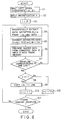
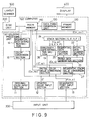
- FIG. 9 is a block diagram showing, in more detail, the internal configuration of the coloring processing unit in the apparatus shown in FIG. 1.
- FIG. 10 is a view showing a pictorial image subject to processing by the coloring processing unit shown in FIG. 9.
- FIG. 11 is a view for explaining a coloring processing of the pictorial image shown in FIG. 10.
- FIG. 12 is a view showing the state where the pictorial image shown in FIG. 10 is expressed by runlength data.
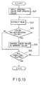
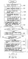
- FIG. 13 is a flowchart showing the procedure of a coloring processing by a first method in the coloring processing unit shown in FIG. 9.
- FIG. 14 is a flowchart showing the procedure of a coloring processing by a second method in the coloring processing unit shown in FIG. 9.
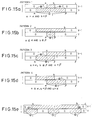
- FIGS. 15a to 15e and FIGS. 16a to 16e are views showing patterns untilized at the procedure shown in FIG. 14, respectively.
- FIG. 17 is a block diagram showing, in more dail, the internal configuration of the draw processing unit 142 in the apparatus shown in FIG. 1.
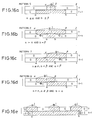
- FIG. 18 is a view defining color values with respect to pictorial images shown in succeeding drawings.
- FIGS. 19a and 19b are views showing a pictorial image subject to processing by the draw processing unit shown in FIG. 17 and runlength data thereof, respectively.
- FIGS. 19c and 19d are views showing a pictorial image processed by the draw processing unit shown in FIG. 17 and runlength data thereof, respectively.
- FIG. 20 is an explanatory view of a brush diagram used for processing by the draw processing unit shown in FIG. 17.
- FIG. 21 is an explanatory view of a method of inputting a drawing area by the draw processing unit shown in FIG. 17, and FIG. 22 is a view showing a drawing area inputted by this inputting method.
- FIG. 23 is an explanatory view showing another method of inputting a drawing area by the draw processing unit.
- FIGS. 24a to 24f are views showing six judgement patterns used for processing by the draw processing unit shown in FIG. 17, respectively.
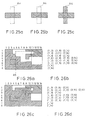
- FIGS. 25a to 25c are views for explaining an original color designated draw processing by the draw processing unit shown in FIG. 17, respectively.
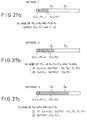
- FIGS. 26a and 26b are views showing a pictorial image subject to the original color designated draw processing unit shown in FIG. 17 and runlength data thereof, respectively.
- FIGS. 26c and 26d are views showing a pictorial image to which the original color designated draw processing is implemented by the draw processing unit shown in FIG. 17 and runlength data thereof, respectively.
- FIGS. 27a to 27f are views showing six judgement processing patterns used for the original color designated draw processing by the draw processing unit shown in FIG. 17, respectively.
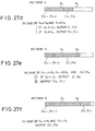
- FIG. 28 is a flowchart showing the procedure in which a method of inputting a polygon according to this invention is applied to an apparatus for preparing a screen tint film.
- FIG. 29 is a view showing a picture display at the time when five vertices (P 1 , P 2 , ..., P 5 ) are inputted in the method shown in FIG. 28.
- FIG. 30 is a view showing the state where a pentagon is determined by connecting a start point and an end point from the state of FIG. 29.
- FIG. 31 is a view showing the state where auxiliary points are inputted from the state of FIG. 29.
- FIG. 32 is a view showing a pentagon determined by inputing of auxiliary points shown in FIG. 31.
- FIG. 33 is a view showing the state where different auxiliary points are inputted from the state of FIG. 29.
- FIG. 34 is a view showing a square determined by inputting of auxiliary points shown in FIG. 33.
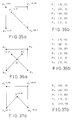
- FIGS. 35a and 35b are views showing a picture display at the time point when five vertices are inputted and coordinates in the memory in the method shown in FIG. 28, respectively.
- FIGS. 36a and 36b are views showing the state where auxiliary points are inputted from the state of FIGS. 35a and 35b.
- FIGS. 37a and 37b are views showing the state where a pentagon is determined by inputting of auxiliary points shown in FIGS. 36a and 37b.
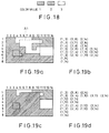
- FIG. 38 is an explanatory view of a scan conversion processing
- FIG. 39 is a view showing a table obtained as the result of the scan conversion processing.
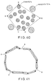
- FIG. 40 is a view showing the state where designation of a screen tin area is made by inputting of a polygon.
- FIG. 41 is a view showing the state where designation of an area encompassed by a contour line having line break portions is made by inputing of a polygon.
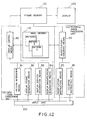
- FIG. 42 is a block diagram showing a basic configuration of an apparatus for preparing a screen tint film according to an embodiment of this invention.
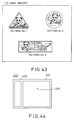
- FIG. 43 is a view showing a pattern stored in the main memory of the apparatus shown in FIG. 42.
- FIG. 44 is a view showing a picture on the display unit in the apparatus shown in FIG.42.
- FIGs. 45a and 45b are views showing a partial expanding display function of a pattern by the apparatus shown in FIG. 42.
- FIGS. 46a and 46b are views showing a whole contracting display function of a pattern by the apparatus shown in FIG. 42.
- FIGS. 47a and 47b are views showing a same picture display function of a plurality of patterns of the apparatus shown in FIG. 42.
- FIG. 1 is a block diagram showing the configuration of a pictorial image processing system according to an embodiment of this invention.
- the invention is applied to an apparatus for preparing a screen tint film.
- the system of FIG. 1 constitutes, in an actual sense, an apparatus for preparing a screen tint film.
- the body of this apparatus is a computer 100.
- a disk unit 200, an input unit 300, and a visual display 400 are connected to the computer 100.
- the input unit 300 typical input devices such as keyboard, mouse, and the like may be used.
- a layout scanner 500 is connected to the disk unit 200. Data of monochromatic picture constituted by contour lines is taken into by the layout scanner 500 and is once retained into the disk unit 200.
- This pictorial image data is taken into the computer 100.
- a pictorial image processing such as a coloring, etc. is implemented thereto and is then returned into the disk unit 200 for the second time.
- the layout scanner 500 takes thereinto processed pictorial image data from the disk unit 200.
- a screen tint film is prepared on the basis of the pictorial image data.
- the internal configuration of the computer 100 will now be described.
- the internal configuration of the computer 100 is actually constructed by an organic combination of hardware such as CPU, memory and the like and software for operating the hardware. Let now consider the components classified into function blocks.
- Pictorial image data read out from the disk unit 200 is stored into the main memory 110.
- the pictorial image data in the main memory 110 is transferred into the frame memory 120. As described later, that data is passed through a data form conversion unit 130. Thus, the form of data is converted.
- a picture display is conducted on the visual display 400.
- An operator carries out a pictorial image processing such as a coloring, etc., while looking at this picture display.
- An instruction of the pictorial image processing from the operator is given to a pictorial image processing unit 140 through the input unit 300.
- the key point of this invention is that a scheme is adopted to retain pictorial image data in the main memory 110 in the form of runlength data.
- elements having a function to store pictorial image data are three elements of the disk unit 200, the main memory 110, and the frame memory 120.
- the disk unit 200 and the main memory 110 retain pictorial image data in the form of runlength data
- the frame memory 120 retains pictorial image data in the form of raster data.
- the data form conversion unit 130 has a function to convert runlength data in the main memory 110 to raster data, thus to transfer it to the frame memory 120.
- this pictorial image is expressed by runlength data, it is expressed as shown in FIG. 3.
- One unit of data takes a form of (c, a) wherein c represents a color value that a pixel has and a represents a column value showing the termination of an arrangement of pixels having the same color value.
- c represents a color value that a pixel has
- a represents a column value showing the termination of an arrangement of pixels having the same color value.
- data of (1, 25) is described on the line 1. This indicates that pixels having color value 1 are arranged in succession up to the 25-th column.
- data of (1, 5), (2, 8) and (1, 25) are described on the line 3.
- pixels having color value 1 are first arranged up to the 5-th column, pixels having color value 2 are arranged from the 6-th column to the 8-th column, and pixels having color value 1 are further arranged from the 9-th column to the 25-th column.
- pictorial image data is expressed in the form of such runlength data
- the entire pictorial image can be expressed as long as the data volume of 184 bytes in total.
- the memory capacity can be saved to much extent.
- a of one (c, a) of data is a column value showing a termination of an arrangement of pixels having the same color value in the above-described embodiment
- the number of pixels having the same color value may be used as the column value.
- that line may be described by data of (1, 5), (2, 3) and (1, 17).
- a value capable of indicating the termination of pixels having the same color value in any form may be used.
- the data form conversion unit 130 has a function to convert runlength data in the main memory 110 to raster data to deliver it to the frame memory 120.
- the logic for converting runlength data to raster data is very simple. For example, runlength data of (1, 5), (2, 8), (1, 25) on the line 3 is converted to raster data (11111222111...111). Such a conversion is a conversion with an equal magnification.
- a method of multiplying a coefficient in the state of runlength data as it is to perform an operation corresponding to expansion/ contraction thereafter to convert that runlength data to raster data good efficiency results.
- the pictorial image processing unit 140 has a function to implement a processing such as a coloring or a drawing to runlength data in the main memory 110.
- a processing such as a coloring or a drawing to runlength data in the main memory 110.
- the unit 140 retrieves runlength data subject to processing and modifies it, and then rewrites the content of the memory.
- the coloring provessing unit 141 retrieves data (c, a) subject to coloring to change a color value c of the data to a new color value c' and generates data (c', a) to rewrite old data by new data.
- this pictorial image processing unit includes a polygon input unit 143 having a unique polygon input function.
- the detailed operation of the coloring processing unit 141, the detailed operation of the draw processing unit 142, and the detailed operation of the polygon input unit 143 will be described at chapters ⁇ 3, ⁇ 4 and ⁇ 5, respectively.
- FIG. 4 is a table in which the pictorial image processing system is classified into six types (types A to F) in dependency upon the forms of data caused to be retained into the disk unit, the main memory, and the frame memory, respectively. Since the frame memory is connected to the visual display, it is common for all the types to retain data in the form of raster data.
- the type A is a system of reading raster data from the disk unit directly into the frame memory without using the main memory. In the case of this type, since read-in speed from the disk unit is slow, the operability is poor and is therefore not practical.
- the type B is a system in which a main memory is provided between the disk unit and the frame memory, thus allowing a speed for reading data into the frame memory to be improved.
- the type C is a system in which runlength data is employed as the data form of the main memory in order to reduce the capacity of the main memory.
- this system has a procedure to convert raster data to runlength data thereafter to convert it to raster data for the second time, resulting in poor efficiency.
- the types D to F are such that the disk unit is in the form of runlength data. As compared to the types A to C, the occupied capacity of data in the disk unit can be reduced to much extent.
- the type D is a system of reading data from the disk unit directly into the frame memory without using the main memory. However, the operability is poor in the same manner as in the type A.
- the type E is a system of effecting a conversion to raster data at the time of reading data from the disk unit into the main memory. Conventional devices adopt the system of this type. However, as previously described, there are the problems that a large capacity of the main memory is required and the computational efficiency of the image processing is poor. This invention adopts the last-mentioned type F.
- the disk unit and the main memory both retain data in the form of runlength data, the memory efficiency is very good. Particularly, since the capacity of a high cost main memory is reduced, cost is reduced. Further, since a pictorial image processing such as a coloring or drawing, etc., is implemented to runlength data in the main memory, the computational efficiency in the image processing is also improved. Especially, in the case of a picture like a tint screen film, if the pictorial image data is caused to be in the form of runlength data, data volume is extremely reduced as compared to the raster data. Accordingly, application of this invention to such a pictorial image is very advantageous.
- the pictorial image processing system of this invention adopts an approach to allow the disk unit and the main memory to both retain image data in the form of runlength data, and to convert the data form to raster data when data is transferred from the main memory to the frame memory. Accordingly, a memory capacity required for the main memory is lowered, resulting in a reduced cost. Since various computational processing are implemented to runlength data in the main memory, more efficient computational processing can be carried out as compared to conventional devices which have implemented various processing to raster data.
- FIG. 5 is a block diagram showing, in more detail, the internal configuration of the data form conversion unit 130.
- the body of this apparatus is a computer 100.
- a disk unit 200, an input unit 300, and a visual display 400 are connected to the compute 100.
- the input unit 300 as previously described, typical input devices such as keyboard, mouse, and the like may be used.
- a layout scanner 500 is connected to the disk unit 200.
- the internal configuration of the computer 100 will now be described.
- the internal configuration of the computer 100 is actually constructed by an organic combination of hardware such as CPU, memory and the like and software for operating the hardware. Let now consider the components classified into function blocks.
- Picture data read out from the disk unit 200 is stored into the main memory 110.
- the picture data in the main memory 110 is transferred into the frame memory 120 through a path which will be described later.
- a picture display is conducted on the visual display 400.
- An operator carries out an image processing such as a coloring, etc., while looking at this picture display.
- An instruction of the pictorial image processing from the operator is given to a pictorial image processing unit 140 through the input unit 300.
- the pictorial image processing unit 140 updates pictorial image data in the main memory 110 on the basis of this instruction. This method will be described in detail at ⁇ 3 and chapters succeeding thereto.
- the updated pictorial image data is transferred to the frame memory 120.
- an updated picture display is conducted on the visual display 400. Accordingly, after an operator gives an instruction of a pictorial image processing such as coloring, he can immediately confirm that processed result on the visual display 400.
- the main memory 110 retains pictorial image data in the form of raster data, but this apparatus is characterized in that the main memory 110 retains pictorial image data in the form of runlength data.
- the frame memory 120 requires the form of raster data in order to display a picture on the visual display 400. For this reason, conversion of the data form must be carried out in the process for transferring pictorial image data to the frame memory 120.
- conversion of the data form must be carried out in the process for transferring pictorial image data to the frame memory 120.
- it is also require to perform an expansion/contraction computation. The feature of this device resides in that such a processing can be made. This data transfer process will now be described in detail.
- runlength data (c, a) in the main memory 110 is extracted by a runlength extraction section 131.
- a magnification conversion processing is implemented to the runlength data (c, a) at a magnification conversion section 132, resulting in runlength data (c, A).
- a raster data generation section 133 converts this runlength data to raster data to deliver it to the frame memory 120.
- pictorial image data in the main memory 110 is transferred to the frame memory 120.
- This transfer process is carried out on the basis of an instruction of an operator. Namely, the operator gives display object information and a magnification to a display object information input section 134 and a magnification input section 135, respectively.
- the display object information is information indicating which portion of one pictorial image held in the main memory 110 is displayed
- the magnification is a value indicating by what expanding rate or contracting rate a pictorial image is displayed on the visual display.
- the runlength extraction section 131 extracts runlength data participating in the display object information from the main memory 110 on the basis of given display object information.
- the magnification conversion section 132 performs a computation of conversion of magnification on the basis of give magnification.
- FIG. 6 is a flowchart of this process. It is now assumed that one pictorial image as shown in FIG. 2a is stored into the main memory 110. Of course, in an actural sense, data is held or retained in the form of runlength data as shown in FIG. 3.
- an operator has a desire to take a partial pictorial image indicated by the area Q in FIG. 7 as the display object area to display a pictorial image obtained by magnifying that partial pictorial image two times on the visual display 400.
- the area Q is a partial pictorial image of 6x4 pixels.
- a pictorial image of 12x8 pixels is provided on the visual display 400 as shown in FIG. 8a.
- the processing procedure until such a magnified pictorial image is provided will be described in accordance with the flowchart of FIG. 6.
- a left upper coordinate ( ⁇ , ⁇ ) is inputted wherein ⁇ and ⁇ represent coordinate values of a pixel P1 at the left and upper part of the display object area Q as shown in FIG. 7.
- a magnification k is inputted.
- the above-mentioned input operations are implemented to the display object information input section 134 and the magnification input section 135 through the input unit 300 (e.g., key board), respectively. It is to be noted that it is sufficient in the apparatus of this embodiment that only left and upper coordinate values ( ⁇ , ⁇ ) is inputted as information indicative of the display object area. While it is of course that if there is no information indicative of a size of the area Q (e.g., the number of pixels in line and column directions of the area Q), the area Q cannot be specified, the size of the area Q is indirectly determined by the size of the frame memory 120 and the magnification k in this apparatus. For example, if the size of the frame memory 120 is 12 pixels x 8 pixels as shown in FIG. 8a and the magnification k is equal to 2, the area Q is automatically determined by specifiying only the position of the pixel P1.
- the size of the frame memory 120 is 12 pixels x 8 pixels as shown in FIG. 8a and the magnification k is equal to 2
- step S3 an initial value of a parameter j indicative of line is set to ⁇ .
- the initial value of j is also equal to 4. This means that it is sufficient to start extraction of runlength data from the fourth line.
- the runlength data extraction section 131 conducts an extraction from data on the fourth line of the runlength data shown in FIG. 3.
- the extraction section 131 extracts, in order, data (c, aij) which satisfies aij > ⁇ from data on the j-th line where (c, aij) means the i-th data from the left on the j-th line of runlength data shown in FIG. 3.
- the initial value of j is equal to 4 and ⁇ is equal to 8
- the second data (2, 9) from the left on the fourth line is first extracted as data which satisfies the above-described condition.
- the data thus extracted is sent to the magnification conversion section 132.
- an operation of magnification is implemented thereto.
- This magnification operation is an operation for providing ( c, (aij - ( ⁇ - 1)) k ) on the basis of the extracted data (c, aij).
- A (aij - ( ⁇ - 1)) k
- the above-mentioned operation can be said to be an operation for converting data (c, aij) to data (c, A).
- the data (2, 4) thus converted is delivered to the raster data generation section 133.
- the raster data generation section 133 generates raster data from the converted data (2, 4). Namely, raster data (2, 2, 2, 2) comprised of successive four pixels having color value 2 is generated. This raster data is stored into the first line in the frame memory 120 with data elements being closely arranged from the left. This corresponds to the first to the fourth columns on the first line in FIG. 8a.
- step S7 whether or not the frame memory 120 overflows by one line is judged. Namely, whether or not the first line being stored at present overflows is judged. In the case of this example, as shown in FIG. 8a, since the fifth column and columns succeeding thereto are empty, the first line does not overflow.
- the processing procedure returns to the step S4.
- the runlength extraction section 131 extracts the next data. Namely, the third data (1, 25) from the left of the fourth line is extracted.
- the magnification conversion section 132 converts that data to provide converted data (1, 36).
- the raster data generation section 133 generates raster data on the basis of that converted data.
- raster data (1, 1, 1, ..., 1) comprised of successive 32 pixels having color value 1 are generated from the fifth column to the 36-th column, respectively.
- These raster data are stored being closely arranged from the fifth column in the first line of the frame memory 120.
- color values 1 are filled until the 12-th column, so the first line would overflow.
- color values from the 13-th column to the 36-th column are disregarded.
- the processing procedure proceeds to step S8.
- the data transfer process corresponding to one line has been described as above.
- This copy processing is defined as a processing such that the raster data generation section 133 generates raster data corresponding to (k-1) lines, which are exactly the same as that of the preceding line, to memorize them into succeeding (k-1) lines of the frame memory.
- the value of j is updated at step S10.
- updated j is equal to 5.
- the overflow of the frame memory indicates the case where raster data have been stored into all the lines of the frame memory 120.
- the above-mentioned overflow indicates the case where raster data are stored into all lines up to the eight line of FIG. 8a.
- the processing procedure returns to the step S4 for a second time.
- step S8 since k ⁇ 1 holds, the processing procedure proceeds to step S12.
- step S10 j is increased by 1, whereas, at step S12, j is increased by 1/k. Namely, when k is equal to 1/2, j is increased by 2. Thus, an updated value of j becomes equal to 6.
- runlength data of the sixth line of FIG. 3 will be extracted from the next time. In other words, the fifth line is thinned out.
- raster data of the first line of FIG. 8b is generated on the basis of runlength data of the fourth line of FIG. 3, and raster data of the second line of FIG. 8b is generated on the basis of runlength data of the sixth line of FIG. 3.
- a display picture of which size is reduced to one half as shown in FIG. 8b is provided.
- data form conversion unit 130 has been described in accordance with the embodiment, this invention is not limited to such an embodiment, but may be modified in various forms.
- an approach is employed in the above-described embodiment to implement magnification conversion to a unit data (c, a) each time to determine data (c, A) to convert it to raster data to store it into the frame memory.
- An approach is instead employed to first conduct a magnification conversion corresponding to one line thereafter to correctively determine raster data corresponding to one line to correctively transfer raster data corresponding to one line to the frame memory.
- an approach may be employed to first conduct a magnification conversion corresponding to one display picture thereafter to sequentially convert it to raster data to transfer it to the frame memory.
- the pictorial image processing system has a scheme to hold pictorial image data in the form of runlength data in the main memory to extract a necessary portion of this pictorial image data to implement magnification conversion thereto thereafter to convert it so as to take the form of raster data to transfer it to the frame memory.
- the capacity of the main memory can be lowered, resulting a reduced cost, and high efficient expansion/contraction computation can be performed.
- FIG. 9 is a block diagram showing in more detail the internal configuration of the coloring processing unit 141 of the apparatus shown in FIG. 1.
- the internal configuration of the coloring processing unit 141 will be first describe.
- An instruction of a pictorial image processing from an operator is given to an original color input section 11, an updated color input section 12 and a designated point input section 13 through the input unit 300.
- the first method is an original color inputting method
- the second method is a designated point inputting method.
- a coloring instruction is given in the form of "Allow a portion of a first color (original color) in a pictorial image to be colored into a second color (updated color)". Namely, when an original color and an updated color are inputted to the original color input section 11 and the updated color input section 12, respectively, a portion of the original color in the pictorial image is colored by the updated color.
- This processing is carried out by a sequential data extraction section 14 and a color conversion section 15.
- a coloring instruction is given in the form of "Allow a closed area including a point P in pictorial image to be colored into a predetermined color (updated color)". Namely, when coordinate values of the point P in the pictorial image P and an updated color are inputted to the designated point input section 13 and the updated color input section 12, respectively, a closed area including the point P in the pictorial image (contiguous portions having the same color) is colored by the updated color.
- This processing is carried out by respective sections designated by reference numerals 21 to 27.
- FIG. 10 The coloring method by inputing of original color will be first described.
- a pictorial image as shown in FIG. 10 is stored in the main memory 110.
- This pictorial image is composed of three closed areas of an area Q0 serving as a background and areas Q1 and Q2 serving as a pattern (both areas are indicated by hatched lines).
- the area Q0 is comprised of a set of pixels having color value 0, and the areas Q1 and Q2 are each comprised of a set of pixels having color value 1.
- the area Q1 is divided into nine portions labeled R1 to R9 as shown in FIG. 11.
- runlength data of lines up to the sixth line are as shown in FIG. 12. It is to be noted that each element (c, a) of such runlength data will be called "run" hereinafter.
- step S21 an operator inputs an original color and an updated color. Namely, by means of the input unit 300 such as a key board, color value 1 and 2 are inputted into the original color input section 11 and the update color input section 12, respectively.
- the sequential data extraction section 14 extracts runs one by one from runlength data in the main memory 110 to transfer them to the color conversion section 15. Extraction of runs may be carried out in a predetermined order. For example, there may be employed a method of extracting runs from upper lines and from the left within the same line in order. In the example of FIG. 12, runs are extracted in order of (0, a),(0, b), (1, c), ....
- step S23 whether or not color values of the extracted runs are equal to that of the original color is judged.
- runs (0, a) and (0, b) both have a color value of 0 and are not equal to that of the original color, but run (1, c) has a color value of 1 which is equal to that of the original color.
- a color value of runs equal to the original color is changed to that of an updated color. Accordingly, run (1, c) is newly changed to run (2, c).
- Such a processing is repeatedly implemented to all runs (step S25). Such a change of run is carried out at the color conversion section 15.
- the main memory 110 is rewritten by the changed run data. Eventually, all runs having color value 1 in FIG. 12 rewritten into runs having color value 2, and the areas Q1 and Q2 of FIG. 10 are colored by an updated color.
- the point P of FIG. 10 is included in the portion R5 of FIG. 11. Accordingly, it is sufficient to first color a run corresponding to the portion R5. Namely, a run (1, m) of the line 4 of FIG. 12 is changed to a run (2, m). Then, retrieval processing for searching portions adjacent to the upper or lower part of the portion R5 and having color value 1 is conducted. In the case of this example, portion R3 and R6 are found out. Then, runs corresponding to these portions R3 and R6 are extracted to carry out the processing for changing the color value so that it is equal to 2.
- index data is used in this example.
- One index data is composed of four elements of (S, E, Y, F).
- S and E represent coordinate values in a column direction in the figure.
- Y corresponds to the line No. in the figure.
- F is a flag indicating a retrieval direction wherein "up” indicating an upward direction and a "dn" indicating a downward direction are used. The detail of the retrieval processing using such index data will be described later.
- a designated point P (x, y) is inputted. Namely, coordinate values (x, y) is given to the designated point input section 13 through the input unit 300.
- a coordinate input device such as a mouse
- an operator can designate a desired position while looking at a picture displayed on the visual display 400.
- a starting point run (c 0 , a 0 ) is extracted.
- This starting point run is a run inclusive of the position of an inputted point P.
- the portion R5 in FIG. 11 is a portion inclusive of the position of the point P
- a run corresponding thereto is the fourth run (1, m) of the line 4 in FIG. 12.
- run (1, m) is extracted as the starting point run.
- a color value of this starting point run is recognized as an original color. Namely, color value "1" is recognized as the original color.
- step S30 the color value of the starting point run is changed to that of the updated color. Namely, the starting point run (1, m) is changed to (2, m), and is then written into the main memory 110. Thus, the color of portion R5 of FIG. 11 is changed to the updated color.
- steps S28 to S30 are executed at the initial color value conversion section 21. The operation of the initial color value conversion section 21 will be described in accordance with the block diagram of FIG. 9 as follow.
- a starting point run (c 0 , a 0 ) is extracted from the main memory 110 on the basis of coordinate values (x, y) of a point P given from the designated point input section 13. This may be accomplished by determining a corresponding line from the y coordinate value and examining runs (c, a) on the corresponding line in order from the left side to extract such a first run to satisfy a ⁇ x as a starting point run. In the example of FIG. 12, it is first determined that a corresponding line is line 4 from the y coordinate value.
- index data is generated on the basis of the starting point run and is then accumulated into the stack.
- the initial data storage section 22 gives a starting point run (c 0 , a 0 ) to the index data generation section 23 to accumulate the index data generated as that result into the stacked section 24.
- the index data generation section 23 generates two index data expressed below: (s, e, y+1, dn) and (s, e, y-1, up). Where s is an X-coordinate value of a run preceding the starting point run by one, e is an X-coordinate value of the starting point run (i.e., a 0 ), and y is No. of a line where the starting point run is positioned.
- index data generated on the basis of this run are as follows: (l, m, 5, dn) and (l, m, 3, up). These two index data are accumulated or stored into the stack section 24 as initial data. The duty of the initial data storage section 22 is completed. The generation of index data at times subsequent thereto and the storage work are carried out by the sequential data storage section 25.
- the index data takes a form of (S, E, Y, F).
- This index data gives an instruction for carrying out a work for extracting a run which satisfies the following three conditions, and therefore it can be considered that the index data indicates a retrieval target area.
- the three conditions are as follows:
- runs overlapping with sections S to E means runs indicating pixel trains such that a portion (or the whole) thereof is positioned on columns (S+1) to column E.
- dn or up which is a flag indicating the direction is utilized for a pattern recognition (which will be described later) in the case of generating new index data on the basis of extracted runs.
- condition 3 is not a condition directly included in the index data, but a condition common to all index data. Accordingly, it can be considered that index data (l, m, 5, dn) of the above-described actual example gives an instruction for carrying out a work for retrieving runs which satisfy the following three conditions. Namely, the three conditions are as follows:
- the index data (l , m, 3, up) means an instruction to extract similar runs from runs on the line 3. In the example of FIG. 11, it results that run with respect to the portion R3 will be extracted.
- the procedure up to the steps S31 which has been described above is so called a procedure for carrying out the initialization.
- two index data will be accumulated into the stack section 24.
- the repetitive works from the step S32 up to the step S37 are works for repeating processing to read out one index data from the stack, to retrieve a corresponding run on the basis of the instruction of this index data, to implement coloring processing to the corresponding run, to further generate new index data on the basis of the corresponding run, and to accumulate generated index data into the stack. When such a repetition is continued until the stack is empty, a desired coloring work is completed. This repetitive work will now be described.
- step S32 whether or not the stack is empty is judged. As previously described, at the time point when the stack is empty, this repetitive work is completed. In the case where index data remain in the stack, any one of index data is read out at step S33. In the case where a plurality of index data are accumulated, readout operation may carried out even from any index data. In this embodiment, readout operation is carried out in order of First In Last Out. Subsequently, at step S34, a retrieval target area indicated by this index data is retrieved to judge whether or not there is a corresponding run. As a result, if the corresponding run is present, that run is extracted at step S35.
- the runlength data extraction section 26 has a function to read out one index data from the stack section 24 to retrieve the main memory 110 on the basis of the index data and the color value c 0 of the starting point run described in the initial color value conversion section 21 to extract a corresponding run.
- the extracted corresponding run is delivered to the sequential data storage section 25 and the sequential color value conversion section 27.
- the runlength data extraction section 26 delivers index data read out from the stack section along with the extracted run to the sequential data storage section 25.
- the sequential color value conversion section 27 in FIG. 9 carries out a work for changing the extracted corresponding run (c 0 , a) to (c', a) to write the changed run into the main memory 110.
- new index data is generated on the basis of the corresponding run and the index data used for retrieving this corresponding run.
- the new index data thus generated is accumulated into the stack.
- the sequential data storage section 25 carried out this work.
- the sequential data storage section 25 receives, as described above, the run and the index data from the runlength data extraction section 26 and delivers it to the index data generation section 23 to generate new index data which is accumulated into the stack section 24.
- the processing procedure returns to the step S34 for a second time. Namely, whether or not there is a corresponding run based on the same index data is judged. Since a corresponding run which satisfies three conditions that one index data indicates is not generally limited to one, the processing at the steps S35 to S37 will be repeated for all corresponding runs. When the processing for all corresponding runs is completed, the processing procedure returns from the step S34 to the step S32. Namely, new index data is read out from the stack and exactly the same processing will be repaeated on the basis of this index data. Such a work is repeated until the stack becomes empty.
- this processing can be said to be "a processing for generating new index data on the basis of index data (S, E, Y, F) and a run (c 0 , a) extracted on the basis of this index data".
- This processing will be separately described in connection with the case where a flag F indicating the direction is dn and the case where that flag F is up.
- FIG. 15a This diagram shows pixel trains positioned on the line (Y-1) and the line Y therebelow where numbers in the pixel trains indicate color values of those pixel trains. Expression of these pixel trains by runlength data is as follows: (0, a) (1, b) (0, c) (0, ⁇ ) (1, ⁇ ) (0, ⁇ ).
- an arbitrary run (1, b) is extracted, and this run is changed to (2, b), that is, the coloring processing has been completed, and index data (a, b, Y, dn) has been generated on the basis of this run.
- index data a, b, Y, dn
- a run of (1, ⁇ ) is found out on the line Y.
- the run (1, ⁇ ) satisfies the following three conditions:
- FIG. 15a shows the state where such a run (1, ⁇ ) is extracted.
- the case where a run is extracted on the line Y is not limited to the case of FIG. 15a, but may be cases as shown in FIGS. 15b to 15d.
- FIGS. 15b to 15d Eventually, as the pattern of a corresponding run of the line Y, there results any one of patterns 1 to 4 shown in FIGS. 15a to 15d.
- the logic conditions of respective patterns are shown together in the figure. Accordingly, as the retrieval work, a logic work for searching a run which satisfies any one of logic conditions of these patterns is carried out.
- the runlength data extraction section 26 deliveres this corresponding run (1, ⁇ ) to the sequential color value conversion section 27.
- the corresponding run (1, ⁇ ) is changed to (2, ⁇ ), and is then written into the main memory 110.
- index data (a, b, Y, dn) is delivered to the sequential data storage section 25 along with the corresponding run (1, ⁇ ).
- the index data generation section 23 generates new index data on the basis of these data.
- Index data generated differ from each other depending upon the above-described four patterns. Index data generated for respective patterns are shown as follows:
- index data is generally expressed as (s, e, y, f)
- new index data are generated by arranging a start point s and an end point e of a retrieval target area to be detected from now, a line No. y thereof, and a direction flag f indicating the positional relationship between a line of a run which is extracted and is being processed at present and a line (line No. y) to be retrieved from now.
- line No. y a line of a run which is extracted and is being processed at present and a line (line No. y) to be retrieved from now.
- three new index data of A, B and C are generated. This corresponds to a retrieval target area as indicated in a model form by symbols encircling respective alphabets.
- the flag F indicating the direction is required for determining whether the pattern of FIG. 15 is applied, or the pattern of FIG. 16 is applied. This is because where index data of (a, b, Y, F) is given along with the run ( ⁇ , ⁇ ), if a > ⁇ and b ⁇ ⁇ , it is impossible to discriminate whether the pattern 1 is applied or the pattern 6 is applied unless reference is made to the flag F.
- a run (1, m) with respect to the portion R5 is taken out as the starting point run.
- This run is changed to (2, m), and two index data (l, m, 3, up) and (l, m, 5, dn) are generated.
- (l, m, 5, dn) is read out, and a run (1, p) with respect to the portion R6 is extracted as a corresponding run on the line 5.
- the applied pattern at this time is the pattern 1.
- the following three index data are generated and are accumulated into the stack.
- D2 (m, p, 4, up) D3 (o, p, 6, dn).
- index data D3 is read out.
- a run (1, s) with respect to the portion R7 and a run (1, u) with respect to the portion R8 are extracted as corresponding runs on the line.
- the applied pattern of the former is the pattern 3 and the applied pattern of the latter is the pattern 2.
- the following index data are generated: D4 (r, o, 5, up) D5 (r, s, 7, dn).
- index data are accumulated into the stack. Subsequently, the index data D6 is read out. A corresponding run in the line 7 is retrieved. However, no corresponding run is found out. In this case, no new index data is generated. Thus, the next index data D5 is read out. A run with respect to the portion R9 of the line 7 is extracted. At times subsequent thereto, processing is continued in a manner similar to the above.
- the index data has a flag F indicating the direction, but the method described below differs from the former method in that this flag F is not used. Namely, the index data takes a form of (S, E, Y). As new index data, even in either cases of the patterns 1 to 8, two index data described below can be generated at all times: ( ⁇ , ⁇ , Y-1) ( ⁇ , ⁇ , Y+1).
- the logic for generating new index data becomes very simple.
- the demerit with this method is that since an already extracted section is retrieved for the seocond time, a wasteful retrieval work cannot be avoided.
- search for a corresponding run is carried out in connection with the retrieval target areas A, B and C indicated by symbols encircling alphabets.
- the section ab of the line (Y-1) is also included into the retrieval target areas.
- the run existing in the section ab is already extracted and its color values is already changed to 2
- the pattern 2 is an example where such a wastefulness conspicuously appears.
- the retrieval target area is only the section A.
- new index data generated from this pattern there is only one index data ( ⁇ , ⁇ , Y+1).
- wasteful index data of ( ⁇ , ⁇ , Y-1) would be further generated.
- a wasteful retrieval work would be conducted on the basis of this wasteful index data.
- the invention of this application employs, in the pictorial image processing system, a scheme to hold pictorial image data in the form of runlength data in the main memory to implement coloring processing to the runlength data.
- the capacity of the main memory is lowered, thus permitting the cost to be reduced, and a high efficient coloring operation can be performed.
- FIG. 17 is a block diagram showing, in more detail, the internal configuration of the draw processing unit 142 of the apparatus shown in FIG. 1. Initially, the internal configuration of the draw processing unit 142 will be described.
- a data updating section 50 has a function to update runlength data on the basis of input data. This updating work is carried out every data of one line in the main memory 110. Namely, data corresponding to one line is read out from the main memory 110 by means of a line data readout section 60. Each of data corresponding to one line is processed by means of the data updating section 50. Respective processed results are retained or held into the line data writing section 70. When the processing corresponding to one line is completed, the line data writing section 70 writes updated data into the line position where readout operation has been carried out of the main memory 110.
- This draw processing is implemented to pictorial image data in the main memory.
- the main memory 110 retains data in the form of runlength data, it is unable to apply a draw processing as in the prior art to this apparatus as it is.
- the principle of the draw processing is very simple. Namely, in principle, it is sufficient to convert color values of raster data corresponding to pixels in a drawing area to desired color values. Implementation of this processing to each of a great amount of pixels cannot be said to be a high efficient operation by any means.
- FIG. 18 three color values are defined.
- a pictorial image as shown in FIG. 19a is formed by these three colors.
- Runlength data for this pictorial image is as shown in FIG. 19b.
- Such runlength data is retained in the main memory 110.
- an operator draws a picture by a color indicated by the color value 1 with respect to an area indicated by broken lines in the figure.
- the pictorial image after undergone the draw processing is as shown in FIG. 19c, and runlength data corresponding thereto is as shown in FIG. 19d.
- this draw processing can be said to be a processing for rewriting the data shown in FIG. 19b into the data shown in FIG. 19d.
- the first method is a drawing of a picture by brush and the second method is a drawing of a picture by instructing a line segment.
- a brush figure and the position of a central point of the brush are inputted by an operator.
- the brush diagram for example, six kinds of figures such as a circle and a square, etc., as shown in FIG. 20 are prepared.
- a desired brush may be selected from this. It is desirable to display these brush shapes in a menu display area of the visual display 400, thus permitting an operator to select an arbitrary one.
- the position of a central point of the brush may be designated by an input device such as a tablet, etc.
- An actual drawing operation is carried out by successively moving the central point position. For example, as shown in FIG. 21, when selecting a brush figure B1 to designate a start position of the central point by the tablet pen and moving the central point to the right by moving the tablet pen as indicated by an arrow in the figure, the area A2 becomes a draw area as shown in FIG. 22.
- the width of a line segment and end points of that line segment are inputted by an operator.
- an area A3 as shown in FIG. 23 becomes a drawing area.
- a brush figure and an central point position are inputted from the input unit 300 to the brush figure input section 31 and the central point input section 32, respectively.
- a drawing area is determined.
- the width of a line segment and end points of the line segment are inputted to the line segment instruction input section 33.
- a drawing area is determined.
- data relating to the determined drawing area is delivered to the data updating section 50 and the line data readout section 60.
- a pictorial image as shown in FIG. 19c is provided by the draw processing.
- Such a processing can be eventually said to be a processing for changing runlength data as shown in FIG. 19b to runlength data as shown in FIG. 19d.
- this processing is carried out per each line.
- the line data readout section 60 has a function to read out runlength data in the main memory 110 per each line. It is to be noted that lines to be read out are limited to lines related to the drawing area.
- the data updating section 50 examines data (2, 14), judges it to be data which is not related to the drawing area, and outputs that data as it is to the line data writing section 70. Eventually, five data of (1, 3) (3, 4) (1, 10) (3, 11) (2, 14) are retained into the line data writing section 70. When they are written into the line 2, data of the line 2 of FIG. 19d is provided. Since the processing of the line 2 is completed, data of the line 3 is then read into the line data readout section 60. Thus, similar processing is carried out.
- the data updating section 50 can recognize, as a column value, a start point Ps (for convenience, this start position is defined as a position on the left side by one column relative to an actual start position) and an end position Pe of a drawing area with respect to a line being examined on the basis of information indicating a drawing area given from the drawing area input section 30.
- a start point Ps for convenience, this start position is defined as a position on the left side by one column relative to an actual start position
- the start point position Ps of the drawing area is column 4 (the actual start point position is column 5), and the end point position Pe thereof is column 10.
- a color value C of the drawing color is given from the color input section 40.
- the data updating section 50 carries out judgement processing and modification processing using these values Ps, Pe and C.
- Ps, Pe and C When data being examined and data preceding by one are expressed as (Cn, Pn) and (Cn-1, Pn-1), respectively, any one of the following six patterns as illustrated in FIGS. 24a to 24f applies to data being examined. It is to be noted that when there is no data preceding by one, the conditions relating to Cn-1, Pn-1, may be neglected.
- the six patterns have been described as above.
- This apparatus has a draw processing function by designation of an original color. By using this function, only a portion of a color designated as an original color of a designated drawing area can be drawn.
- This function will be described in a concrete manner in conjunction with FIGS. 25. It is now assumed that the color value in FIGS. 25 is the same as that shown in FIG. 18. Let suppose that, as shown in FIG. 25a, a rectangle comprised of color value 2 is depicted on a portion of so called a "ground" comprised of color value 3 and a picture is going to be drawn by making a designation of a drawing area A4 and color value 1 of the drawing color using a brush, etc. In an oridinary draw processing, the inside portion of the drawing area A4 will be all fully painted by color value 1.
- color value 2 is designated as the original color
- portion which has been originally color value 2 of the drawing area A4 is colored into color value 1 as shown in FIG. 25b.
- the ground portion which was not designated as the original color is not changed by any means before and after draw processing.
- color value 3 is designated as the original color
- only the portion which has been originally color value 3 of the drawing area A4 is colored into color value 1 as shown in FIG. 15c.
- Such a function is very convenient in the case of making a fine modification of a picture, or in the case where a pattern which should not be erroneously drawn in the vicinity of the drawing area.
- a pictorial image as shown in FIG. 26a when a draw processing is implemented to a pictorial image as shown in FIG. 26a by making a designation such that the original color has color value 3 and the drawing color has color value 1, a pictorial image as shown in FIG. 26c is provided.
- runlength data shown in FIG. 26b For performing such a pictorial image processing, runlength data shown in FIG. 26b must be converted to runlength data shown in FIG. 26d. This conversion is carried out by substantially the same procedure as that of the previously described ordinary draw processing.
- an original color Co is further added in addition to start point position Ps, end point position Pe and drawing color C of a drawing area as reference values required when the data updating section 50 conducts judgment processing and modification processing. Accordingly, the processing with respect to the six patterns are as shown in FIGS. 27a to 27f, respectively. Namely, judgement as to whether or not Cn and the original color Co are equal is further added. By carrying out respective processing of these six patterns, data of FIG. 26b can be converted to
- the invention of this application employs, in the pictorial image processing system, a scheme to retain pictorial image data in the form of runlength data into the main memory to implement draw processing to the runlength data.
- the capacity of the main memory is lowered, thus permitting the cost to be reduced, and a high efficient draw operation can be performed.
- FIG. 28 is a flowchart showing the procedure in the case where a method of inputting a polygon according to this invention is applied to the apparatus for preparing a screen tint film.
- a coordinate input device is prepared as the input unit in the apparatus shown in FIG. 1. It is preferable to use, as the coordinate input device, a mouse capable of designating an arbitrary position on the visual display 400.
- n number of vertices (P1, P2, ..., Pn) are inputted in order.
- P1, P2, ..., Pn This is a work for designating an arbitrary point using a mouse while looking at the display screen.
- respective vertices are sequentially displayed on the screen, and line segments connecting points sequentially inputted are displayed at the same time.
- FIG. 29 shows a picture display when five vertices (P1, P2, ..., P5) are inputted. Line segments connecting respective vertices in order are displayed together with these vertices (reference numerals indicating respective vertices are not displayed on the screen). Coordinate values of respective vertices are taken into the computer 100.
- step S42 whether or not an auxiliary point is inputted is judged.
- an n side polygon p1 P2 ... Pn is determined at step S43. Namely, the start point P1 and the end point Pn are connected by a line segment.
- a pentagon is determined as shown in FIG. 30.
- the method of connecting the start point and the end point is a method ordinarily carried out from the past, but is not a method according to this invention.
- the method according to this invention resides in a method of inputting an auxiliary point at step S42. Accordingly, the procedure shown in FIG.
- step S42 is adapted so as to make it possible to select two kinds of methods branched at the step S42.
- judgement that "no auxiliary point is inputted" is made.
- the next step S43 is executed.
- auxiliary point Px is the (n+1)-th point in an actual sense.
- an operator designates an auxiliary point Px at a position as shown in FIG. 31 by means of a mouse.
- a line segment connecting a point designated at present by the mouse and a vertex Pn designated last is also displayed.
- a line segment connecting the point P5 and the point Px is displayed.
- step S45 intersecting points of the line segment PnPx and respecitve line segments displayed on the visual display are determined (step S45).
- the line segment P5Px intersects with the line segment P1P2, the line segment P2P3, the line segment P3P4 and the line segment P4P5 is examined.
- recognition of this intersecting point can be made by a geometrical operation using coordinate values of respective points. Further, coordinate values of the intersecting point Q can be calculated by an operation.
- step S46 a branch is made depending on whether or not there is an intersecting point. As a result, when there is no intersecting point, the processing procedure returns to the step S42. For example, in FIG. 31, when Px' is designated as an auxialiry point, no point intersecting with any other line segments is produced.
- a square having the points Q, P3, P4 and P5 as respective vertices is determined.
- an operator can freely define a final polygon by the manner of determining the position of the auxiliary point Px from the state shown in FIG. 29.
- the method of designating auxiliary points at the steps S44 to S47 has an extremely high degree of freedom and satisfactory operability as compared to the method of mechanically connecting the start point and the end point as at the step S43.
- a final polygon is restricted by vertices once determined.
- the method of designating an auxiliary point it is posible to completely freely determined a final polygon while using vertices once determined as a criterion.
- FIG. 35a shows the state where five vertices P1, P2, ..., P5 are inputted.
- FIG. 35b shows the state where five vertices P1, P2, ..., P5 are inputted.
- FIG. 35b shows the state where five vertices and their coordinate values are recorded into the memory of the computer.
- FIG. 36a coordinate values of the auxiliary point Px are recorded into the memory in addition to five vertices as shown in FIG. 36b.
- the computer can determine coordinate values (10, 10) of the intersecting point Q by computation.
- a pentagon as shown in FIG. 37a is defined and coordinate values of respective vertices are recorded into the memory as shown in FIG. 37b.
- coloring processing by the coloring processing unit 141 can be implemented to the area inside the polygon.
- scan conversion processing is carried out. This is a processing to scan the inside of the polygon determined line by line to thereby determine start point coordinates and end point coordinates in the area on scanning lines. Assuming that, e.g., a polygon as shown in FIG. 37a is determined, scanning in a horizontal direction is implemented to the pentagon along the lines 1 to 20 as shown in FIG. 38. As a result, a table as shown in FIG. 39 is provided. In this table, pairs of areas are provided for respective lines.
- pairs (0, 1) (19, 20) of the area obtained with respect to the line 1 show that the areas up to the lateral coordinates 0 to 1 and those up to the lateral coordinates 19 to 20 are areas inside this pentagon along the line 1 in FIG. 38.
- coloring processing is in turn carried out at step S49. Namely, a predetermined dot density of a predetermined color is given to pixels within the area indicated by pairs of this area.
- the gist of the invention of this application resides in the method of designating an auxiliary point to determine a polygon as described above.
- an area designation method of polygon is applied to an area designation in the apparatus for preparing a screen tint film, peculiar merits are provided.
- FIG. 40 in the case where there are mixed closed areas (indicated by hatching of slanting lines) in which 50% of cyan should be designated and closed areas (indicated by hatching of dots) in which 70% of magenta, with the method of designating an area by a rectangle as in the prior art, respective areas must be designated one by one.
- area designation method by polygon area designation of 50% of cyan is completed only by designating a pentagon ABCDE as shown.
- a polygon for the purpose of determining a polygon, after several vertex positions are inputed, an auxiliary point is finally inputted. Then, an intersecting point of a line segment connecting this auxiliary point and the final vertex and other line segments is determined. Thus, a polygon is determined using this intersecting point as one vertex. Accordingly, an area designation having an extremely good operability can be made.
- FIG. 42 is a block diagram showing the basic configuration of an apparatus for preparing a screen tint film accordingly this embodiment, which corresponds to the apparatus shown in FIG. 1 in another block form.
- this apparatus includes two kinds of memories of the main memory 110 and the frame memory 120. Respective pictorial image data with respect to a plurality of patterns are stored into the main memory 110.
- the frame memory 120 is a memory for carrying out display on the visual display 400. Data in the frame memory 120 are prepared by display control means 80 on the basis of data in the main memory 110.
- the input unit 300 is a device for directly receiving an instruction from an operator. Respective means 81 to 86 are connected to the input unit 300.
- the pattern designation means 81 is means for designating which pattern in the main memory 110 is subject to displaying on the basis of an instruction of an operator given form the input unit 300.
- the display frame designation means 82 is means for designating at which position and at what size a display frame should be defined in the display screen of the visual display 400 on the basis of an instruction of an operator similarly given from the input unit 300.
- the display portion designation means 83 is means for designating which portion of a pattern subject to displaying should be displayed on the basis of an instruction of an operator similarly given from the input unit 300.
- the display magnification designation means 84 is means for designating a magnification for displaying a pattern subject to displaying on the basis of an instruction of an operator given from the input unit 300.
- the display control means 80 carries out a processing to read out data from the main memory 110 on the basis of instruction from respective means 81 to 84 and to write data prepared on the basis of the data thus read out into the frame memory 120. Namely, the display control means 80 recognizes a pattern designated by the pattern designation means 81 and reads out a portion of pictorial image data designated by the display portion designation means 83 from the main memory 110. Subsequently, the display control means 80 carries out a contracting processing for thinning out pixels of read out data or an expanding processing for interpolating pixels of read out data on the basis of a magnification designated by the display magnification designation means 84 to generate now data.
- data in the main memory 110 is runlength data
- data in the frame memory 120 is raster data. Accordingly, as previously described, conversion of data form is carried out in the display control means 80.
- the display control means 80 carries out a processing to recognize, from data in the frame memory 120, data corresponding to a pictorial image in a display frame designated by the display frame designation means 82 and to rewrite the corresponding data into generated new data.
- the visual display 400 carries out a picture display corresponding to data in the frame memory 120. Accordingly, when data in the frame memory 120 is rewritten, a picture display on the visual display 400 is changed to a new picture display.
- the display control means 80 and respective means 81 to 84 correspond to the data form conversion unit 130 in the block diagram of FIG. 1.
- modification/coloring means 90 receives an instruction of modification from the means 85 or an instruction of coloring from the means 86. These instructions include an instruction of position on the display screen of the display 400. This implies that a procedure is taken to pointout, e.g., a specific portion displayed on the visual display 400 to give an instruction of "Modify or color this specific portion".
- the modification/coloring means 90 recognizes a portion, which corresponds to a designated position on the display screen of the visual display 400, in pictorial image data of a pattern in the main memory 110 by making reference to the frame memory 120 and implements modification or coloring processing to the recognized data.
- the modification/coloring means 90 and respective means 85 and 86 correspond to the pictorial image processing unit 140 in the block diagram of FIG. 1.
- the display control means 80 When data is altered as the result of the fact that such a correction or coloring processing is implemented to pictorial image data in the main memory 110, the display control means 80 generates new data on the basis of the altered new data and write them into the frame memory 120. Accordingly, data in the frame memory 120 is updated. As a result, a pictorial image which has undergone correction or coloring processing is displayed on the visual display 400.
- an operator can give an instruction of modification or coloring while looking at the visual display 400 and confirm the result therefore on the visual display 400.
- the main memory 110 and the frame memory 120 may use a common memory of the computer.
- the visual display 400 is a display unit connected to this computer, and the input unit 300 is a device such as a key board or a mouse, etc., connected to this computer.
- the remaining respective means 80, 81 to 86, and 90 may be all realized by software for operating this computer.
- pictorial image data for three patterns as shown in FIG. 43 are stored in the main memory 110. These pictorial image are taken into the main memory 110 by the layout scanner 500 or a video camera (not shown). At the stage where these patterns are taken into the main memory 110, they are binary pictorial image comprised of line drawings which have no color tone and are not colored. In accordance with the coloring work by this apparatus, these patterns become colored pictorial images.
- the pictorial images in which coloring has been completed are outputted from the main memory 110 to a film by the lay out scanner 500 for the second time. In this example, a color visual display is used as the display 400.
- the display picture of this color visual display is divided into two areas of a picture display area 410 and a command display area 420 as shown in FIG. 44.
- a cursor 430 moving interlocking with the movement of a mouse as the the input unit 300 is displayed in these display area.
- this cursor 430 it is possible to designate an arbitrary point in the picture display area 410, or to designate an arbitrary command in the command display area 420.
- the pattern No.2 is designated at the pattern designation means 81
- a display frame 410 of full size of the picture display is designated at the display frame designation means 82
- the entirety of the pattern is designated at the display portion designation means 83
- a full size is designated at the display magnification designation means 84.
- the display control means 80 performs an operation to entirely read out pictorial image relating to the pattern 2 in the main memory 110 to thereby rewrite data in the frame memory 120.
- pictorial image data as shown in FIG. 45a is provided in the frame memory 120, and is displayed on the visual display as it is. It is to be noted that, in the apparatus of this embodiment, a pattern No. display area 440 is provided at the upper part of each display frame to display a pattern No. displayed in that display frame.
- the operator carries out a designation of display magnification. This may be accomplished, e.g., by displaying a magnification command such as double, threefold, one half, or one third, etc., in the command area 420 to designate a desired magnification command by the cursor 430.
- the display control means 80 receives, from respective means 81 to 84, an instruction to display a predetermined portion (the periphery of the cursor 430 of FIG. 45a) of the pattern No. 2 at a predetermined magnification within the display frame 450.
- the display control means 80 carries out work for extracting data around a predetermined portion (an area to be extracted is determined from the size of the display frame 450 and the designated magnification) of pictorial image data relating to the pattern No. 2 in the main memory 110.
- the means 80 implements an expanding processing for interpolating pixels to the extracted data to generate new data.
- a portion of data corresponding to the pictorial image within the display frame 450 in the frame memory 120 is replaced by the newly generated data.
- a display picture on the visual display 400 is as shown in FIG. 45b.
- An expanded pictorial image is displayed within the display frame 450 overlapping with the pattern of full size.
- contour line 460 (indicated by single dotted lines in FIG. 45b) is displayed in this embodiment.
- the contour line 460 indicates a location of the expanded pictorial image displayed in the frame 450.
- Such a display of contour line 460 may be carried out by recognizing an extracted portion of pictorial image data when it is extracted from the main memory 110 by the display control means 80 to update data in the frame memory 120 so that a contour line is depicted at a position corresponding to an extracted portion of a pictorial image of full size.
- An operator can give an instruction of modification for a break portion or an instruction of coloring the inside of a predetermined closed area while looking at such a display.
- designation of a portion to be modified and/or designation of a colored area may be carred out by moving the cursor on the display screen.
- designation in a pictorial image of full size or designation in an enlarged pictorial image may be adopted.
- the modification/coloring means 90 recognizes, on pictorial image data in the main memory 110, a portion corresponding to a position that an operator has designated on the display screen by making reference to data in the frame memory 120 to implement modification or coloring processing to the pictorial image of the recognized portion.
- a break portion of pictorial image data of the pattern No. 2 in the main memory 110 shown in FIG. 43 is modified by the above-mentioned instruction.
- break portions (P3, P4) are displayed in a modified form in both the pictorial image of full size and the expanded pictorial image.
- the coloring processing For example, in the case where an instruction of coloring is given on a picture of full size, a colored result can be obtained not only on the picture of full size but also on the expanded picture.
- the feature of this invention resides in that separate pictures displayed in the form of a multi-window are related to each other, and that pictorial image data which provides the basis of display is unified in the main memory 110.
- FIG. 46b it is possible to designate another display frame 450b to display the entire image of a pattern within this display frame in a contracted manner. It is sufficient that an operator gives an instruction to display the entire image of the pattern No. 2 with a predetermined magnification by designating the display frame defined by, e.g., two points P5 and P6.
- the display control means 80 receives, from respective means 81 to 84, an instruction to display the entirety of the pattern No. 2 within the display frame 450b with a predetermined contraction factor. Responding to this instruction, the display control means 80 carries out a work to extract the entirety of pictorial image data relating to the pattern No.
- FIG. 46b a display picture on the visual display 400 is as shown in FIG. 46b.
- the whole pictorial image of the pattern is displayed in a contracted manner within the display frame 450b overlapping with an expanded pictorial image.
- a contour line 460 (indicated by single dotted lines) indicating an expanded portion is displayed in the display frame 450b.
- FIG. 47a shows the entire pictorial image of the pattern No. 1 within a display frame 450c in a contracted manner as shown in FIG. 47a.
- FIG. 47b shows the state where three patterns are displayed within the same screen as stated above. It is sufficient for an operator to give an instruction to display the entireties of the patterns No. 2 and No. 3 within display frames 450d and 450e with a predetermined contraction factor, respectively.
- the display control means 80 carries out a work to extract the entirety of pictorial image data relating to the patterns No. 2 and No.
- a multi-window display such that a succeeding display picture overlaps with a preceding display picture can be conducted.
- the modification/coloring means recognizes which data in the main memory is caused to correspond to the position designated by the operator by making a reference to the frame memory. Modification or coloring processing is implemented to data in the main memory.
- the above-described pictorial image processing system according to this invention is very effective when that system is applied to an apparatus for preparing a screen tint film using a computer.
- this invention can be applied all pictorial image processing such as CAD equipment, and video systems, etc.
Applications Claiming Priority (19)
| Application Number | Priority Date | Filing Date | Title |
|---|---|---|---|
| JP1024238A JPH0693185B2 (ja) | 1989-02-02 | 1989-02-02 | 画像処理装置 |
| JP2423989 | 1989-02-02 | ||
| JP1024239A JPH0758427B2 (ja) | 1989-02-02 | 1989-02-02 | 画像処理装置 |
| JP124238/89 | 1989-02-02 | ||
| JP124239/89 | 1989-02-02 | ||
| JP2423889 | 1989-02-02 | ||
| JP3750089 | 1989-02-17 | ||
| JP1037500A JPH02216590A (ja) | 1989-02-17 | 1989-02-17 | 画像処理装置 |
| JP137500/89 | 1989-02-17 | ||
| JP4065789 | 1989-02-21 | ||
| JP140657/89 | 1989-02-21 | ||
| JP1040657A JPH0666871B2 (ja) | 1989-02-21 | 1989-02-21 | 画像処理装置 |
| JP18856089A JP2779522B2 (ja) | 1989-07-20 | 1989-07-20 | 多角形の入力方法 |
| JP18856089 | 1989-07-20 | ||
| JP188560/89 | 1989-07-20 | ||
| JP1244840A JPH0693169B2 (ja) | 1989-09-20 | 1989-09-20 | 無地網フィルム作成装置 |
| JP244840/89 | 1989-09-20 | ||
| JP24484089 | 1989-09-20 | ||
| EP90902373A EP0407614B1 (de) | 1989-02-02 | 1990-01-30 | Bildbehandlungsanordnung |
Related Parent Applications (2)
| Application Number | Title | Priority Date | Filing Date |
|---|---|---|---|
| EP90902373A Division EP0407614B1 (de) | 1989-02-02 | 1990-01-30 | Bildbehandlungsanordnung |
| EP90902373.1 Division | 1990-01-30 |
Publications (3)
| Publication Number | Publication Date |
|---|---|
| EP0737937A2 true EP0737937A2 (de) | 1996-10-16 |
| EP0737937A3 EP0737937A3 (de) | 1997-05-14 |
| EP0737937B1 EP0737937B1 (de) | 2000-05-03 |
Family
ID=27549160
Family Applications (2)
| Application Number | Title | Priority Date | Filing Date |
|---|---|---|---|
| EP96110758A Expired - Lifetime EP0737937B1 (de) | 1989-02-02 | 1990-01-30 | Bildverarbeitungsgerät |
| EP90902373A Expired - Lifetime EP0407614B1 (de) | 1989-02-02 | 1990-01-30 | Bildbehandlungsanordnung |
Family Applications After (1)
| Application Number | Title | Priority Date | Filing Date |
|---|---|---|---|
| EP90902373A Expired - Lifetime EP0407614B1 (de) | 1989-02-02 | 1990-01-30 | Bildbehandlungsanordnung |
Country Status (4)
| Country | Link |
|---|---|
| US (1) | US5377023A (de) |
| EP (2) | EP0737937B1 (de) |
| DE (2) | DE69033539T2 (de) |
| WO (1) | WO1990009018A1 (de) |
Families Citing this family (17)
| Publication number | Priority date | Publication date | Assignee | Title |
|---|---|---|---|---|
| JPH04281667A (ja) * | 1991-03-11 | 1992-10-07 | Ricoh Co Ltd | 画像データ符号/復号化装置 |
| US5488486A (en) * | 1991-03-11 | 1996-01-30 | Ricoh Company, Ltd. | Image processing system |
| DE69422324T2 (de) * | 1993-03-29 | 2000-07-27 | Koninkl Philips Electronics Nv | Speicherarchitektur mit Fenstern zum Bildkompilieren |
| EP0618560B1 (de) * | 1993-03-29 | 1999-12-29 | Koninklijke Philips Electronics N.V. | Speicherarchitektur mit Fenstern zum Bildkompilieren |
| US6680782B1 (en) * | 1993-06-30 | 2004-01-20 | Nexpress Solutions Llc | Method and apparatus of using a raster image processor and interpolator to increase the speed of operation and reduce memory requirements for electronic printing |
| US5872874A (en) * | 1995-04-26 | 1999-02-16 | Hewlett-Packard Company | Method and apparatus for scaling down images that are provided in a compressed data format |
| NL1005084C2 (nl) * | 1997-01-24 | 1998-07-27 | Oce Tech Bv | Werkwijze voor het uitvoeren van een beeldbewerkingsoperatie op looplengte gecodeerde bitmaps. |
| US6104441A (en) * | 1998-04-29 | 2000-08-15 | Hewlett Packard Company | System for editing compressed image sequences |
| GB2354925B (en) * | 1999-05-25 | 2003-02-12 | Nippon Telegraph & Telephone | Image filling method ,apparatus and computer readable medium for reducing filling process in producing animation |
| DE10041037A1 (de) * | 2000-08-22 | 2002-03-14 | Ubicom Ges Fuer Telekommunikat | Bildkodierungsverfahren und Bildkodierer |
| WO2002037857A2 (en) | 2000-10-31 | 2002-05-10 | Koninklijke Philips Electronics N.V. | Method and device for video scene composition including graphic elements |
| US6996284B2 (en) * | 2002-03-08 | 2006-02-07 | Global Graphics Software Limited | System and method for flattening spans |
| US8134742B2 (en) * | 2006-07-07 | 2012-03-13 | Canon Kabushiki Kaisha | Output device and method for outputting density data corresponding to a color material to a printing unit |
| WO2010018622A1 (ja) * | 2008-08-12 | 2010-02-18 | 富士通株式会社 | 電子ペーパ端末装置、画像表示制御プログラム、および画像表示制御方法 |
| WO2019043931A1 (ja) * | 2017-09-01 | 2019-03-07 | 本多電子株式会社 | 海図画像表示装置 |
| JP6946894B2 (ja) * | 2017-09-25 | 2021-10-13 | コニカミノルタ株式会社 | 画像形成装置及び画像形成方法 |
| CN111002747A (zh) * | 2019-11-26 | 2020-04-14 | 苏州赛客爱茵智能科技有限公司 | 一种高效刻字膜刻制图案排版方法 |
Citations (2)
| Publication number | Priority date | Publication date | Assignee | Title |
|---|---|---|---|---|
| EP0279420A2 (de) * | 1987-02-20 | 1988-08-24 | International Business Machines Corporation | Verfahren und Vorrichtung zur Herstellung transponierter Bilddaten von einer "run end"- oder "run length"-Bilddarstellung |
| US4792981A (en) * | 1987-09-21 | 1988-12-20 | Am International, Inc. | Manipulation of run-length encoded images |
Family Cites Families (8)
| Publication number | Priority date | Publication date | Assignee | Title |
|---|---|---|---|---|
| JPS6019517B2 (ja) * | 1978-08-22 | 1985-05-16 | 日本電信電話株式会社 | カラ−図形作成処理装置 |
| JPS5856575A (ja) * | 1981-09-29 | 1983-04-04 | Fujitsu Ltd | 画像デ−タ拡大方式 |
| US4780709A (en) * | 1986-02-10 | 1988-10-25 | Intel Corporation | Display processor |
| JPS62216478A (ja) * | 1986-03-17 | 1987-09-24 | Dainippon Screen Mfg Co Ltd | 網ふせ装置 |
| JPS6394372A (ja) * | 1986-10-08 | 1988-04-25 | Mitsubishi Electric Corp | 図形入力装置 |
| JPS63104085A (ja) * | 1986-10-22 | 1988-05-09 | 三洋電機株式会社 | デイスプレイ装置 |
| JPS63177277A (ja) * | 1987-01-19 | 1988-07-21 | Mita Ind Co Ltd | 閉領域の面塗り装置 |
| US5075779A (en) * | 1990-04-27 | 1991-12-24 | Intergraph Corporation | Apparatus and method for interpreting image data for use in a raster plotter |
-
1990
- 1990-01-30 EP EP96110758A patent/EP0737937B1/de not_active Expired - Lifetime
- 1990-01-30 DE DE69033539T patent/DE69033539T2/de not_active Expired - Fee Related
- 1990-01-30 US US07/582,198 patent/US5377023A/en not_active Expired - Fee Related
- 1990-01-30 EP EP90902373A patent/EP0407614B1/de not_active Expired - Lifetime
- 1990-01-30 WO PCT/JP1990/000110 patent/WO1990009018A1/ja active IP Right Grant
- 1990-01-30 DE DE69031446T patent/DE69031446T2/de not_active Expired - Fee Related
Patent Citations (2)
| Publication number | Priority date | Publication date | Assignee | Title |
|---|---|---|---|---|
| EP0279420A2 (de) * | 1987-02-20 | 1988-08-24 | International Business Machines Corporation | Verfahren und Vorrichtung zur Herstellung transponierter Bilddaten von einer "run end"- oder "run length"-Bilddarstellung |
| US4792981A (en) * | 1987-09-21 | 1988-12-20 | Am International, Inc. | Manipulation of run-length encoded images |
Non-Patent Citations (2)
| Title |
|---|
| IBM TECHNICAL DISCLOSURE BULLETIN, vol. 29, no. 8, January 1987, NEW YORK, US, pages 3518-3519, XP002027254 ANONYMOUS: "Image Rotation Method" * |
| SYSTEMS, COMPUTERS, CONTROLS, vol. 13, no. 1, 1982, XP000645228 T. HOSHINO: "PATTERN COLORING TERMINAL USING RUN-LENGTH CODING" * |
Also Published As
| Publication number | Publication date |
|---|---|
| US5377023A (en) | 1994-12-27 |
| DE69033539T2 (de) | 2001-01-18 |
| EP0737937B1 (de) | 2000-05-03 |
| EP0407614A4 (en) | 1992-09-09 |
| DE69031446T2 (de) | 1998-03-19 |
| DE69031446D1 (de) | 1997-10-23 |
| EP0737937A3 (de) | 1997-05-14 |
| DE69033539D1 (de) | 2000-06-08 |
| WO1990009018A1 (en) | 1990-08-09 |
| EP0407614B1 (de) | 1997-09-17 |
| EP0407614A1 (de) | 1991-01-16 |
Similar Documents
| Publication | Publication Date | Title |
|---|---|---|
| EP0407614B1 (de) | Bildbehandlungsanordnung | |
| US7012620B1 (en) | Full-color desktop publishing system | |
| JPH0560144B2 (de) | ||
| EP0589702B1 (de) | Bildverarbeitungsverfahren und -gerät | |
| JPH04192671A (ja) | ピンホール消去方法 | |
| DE19715491A1 (de) | Interpolationsverfahren und -vorrichtung zur schnellen Bildvergrößerung | |
| JPS6255137B2 (de) | ||
| EP0362677A2 (de) | Verfahren und Vorrichtung zur Erzeugung von Ausschneide-Maskendaten | |
| JP2639517B2 (ja) | 画像領域の色付け処理方法 | |
| US5668896A (en) | Method of and apparatus for processing image having a plurality of image areas | |
| US6836571B1 (en) | Method for converting digital raster data of a first resolution into digital target data of a second resolution | |
| JP3111971B2 (ja) | 画像データ補間装置、画像データ補間方法および画像データ補間プログラムを記録した媒体 | |
| EP0418895B1 (de) | Verfahren und Gerät zur Verarbeitung eines Bildes mit mehreren Gebieten | |
| EP0687994A2 (de) | Verfahren und Vorrichtung zur Gewinnung von Konturinformation | |
| JP2791512B2 (ja) | 画像領域指定方法 | |
| JP2577276B2 (ja) | 線切れ部検出方法 | |
| JP2675043B2 (ja) | 図面データの編集方法 | |
| JP2999538B2 (ja) | ワイプパターン指定装置 | |
| JPH0758427B2 (ja) | 画像処理装置 | |
| JP2989261B2 (ja) | 着色処理装置 | |
| JP2662947B2 (ja) | 画像検索方法 | |
| JP3093950B2 (ja) | 輪郭情報抽出装置及びその方法 | |
| CA2256970A1 (en) | Method for accessing and rendering an image | |
| JPH05197366A (ja) | フォントデータ生成装置 | |
| JPH1040313A (ja) | フォーマット作成装置及びフォーマット制御プログラムの作成方法 |
Legal Events
| Date | Code | Title | Description |
|---|---|---|---|
| PUAI | Public reference made under article 153(3) epc to a published international application that has entered the european phase |
Free format text: ORIGINAL CODE: 0009012 |
|
| AC | Divisional application: reference to earlier application |
Ref document number: 407614 Country of ref document: EP |
|
| AK | Designated contracting states |
Kind code of ref document: A2 Designated state(s): CH DE FR GB LI |
|
| PUAL | Search report despatched |
Free format text: ORIGINAL CODE: 0009013 |
|
| AK | Designated contracting states |
Kind code of ref document: A3 Designated state(s): CH DE FR GB LI |
|
| 17P | Request for examination filed |
Effective date: 19970718 |
|
| 17Q | First examination report despatched |
Effective date: 19980722 |
|
| GRAG | Despatch of communication of intention to grant |
Free format text: ORIGINAL CODE: EPIDOS AGRA |
|
| GRAG | Despatch of communication of intention to grant |
Free format text: ORIGINAL CODE: EPIDOS AGRA |
|
| GRAH | Despatch of communication of intention to grant a patent |
Free format text: ORIGINAL CODE: EPIDOS IGRA |
|
| GRAH | Despatch of communication of intention to grant a patent |
Free format text: ORIGINAL CODE: EPIDOS IGRA |
|
| GRAA | (expected) grant |
Free format text: ORIGINAL CODE: 0009210 |
|
| AC | Divisional application: reference to earlier application |
Ref document number: 407614 Country of ref document: EP |
|
| AK | Designated contracting states |
Kind code of ref document: B1 Designated state(s): CH DE FR GB LI |
|
| REG | Reference to a national code |
Ref country code: CH Ref legal event code: EP |
|
| REF | Corresponds to: |
Ref document number: 69033539 Country of ref document: DE Date of ref document: 20000608 |
|
| ET | Fr: translation filed | ||
| REG | Reference to a national code |
Ref country code: CH Ref legal event code: NV Representative=s name: PATENTANWALTSBUERO FELDMANN AG |
|
| PLBE | No opposition filed within time limit |
Free format text: ORIGINAL CODE: 0009261 |
|
| STAA | Information on the status of an ep patent application or granted ep patent |
Free format text: STATUS: NO OPPOSITION FILED WITHIN TIME LIMIT |
|
| 26N | No opposition filed | ||
| PGFP | Annual fee paid to national office [announced via postgrant information from national office to epo] |
Ref country code: GB Payment date: 20011218 Year of fee payment: 13 |
|
| PGFP | Annual fee paid to national office [announced via postgrant information from national office to epo] |
Ref country code: FR Payment date: 20011221 Year of fee payment: 13 |
|
| REG | Reference to a national code |
Ref country code: GB Ref legal event code: IF02 |
|
| PGFP | Annual fee paid to national office [announced via postgrant information from national office to epo] |
Ref country code: DE Payment date: 20020327 Year of fee payment: 13 |
|
| PGFP | Annual fee paid to national office [announced via postgrant information from national office to epo] |
Ref country code: CH Payment date: 20020426 Year of fee payment: 13 |
|
| PG25 | Lapsed in a contracting state [announced via postgrant information from national office to epo] |
Ref country code: GB Free format text: LAPSE BECAUSE OF NON-PAYMENT OF DUE FEES Effective date: 20030130 |
|
| PG25 | Lapsed in a contracting state [announced via postgrant information from national office to epo] |
Ref country code: LI Free format text: LAPSE BECAUSE OF NON-PAYMENT OF DUE FEES Effective date: 20030131 Ref country code: CH Free format text: LAPSE BECAUSE OF NON-PAYMENT OF DUE FEES Effective date: 20030131 |
|
| PG25 | Lapsed in a contracting state [announced via postgrant information from national office to epo] |
Ref country code: DE Free format text: LAPSE BECAUSE OF NON-PAYMENT OF DUE FEES Effective date: 20030801 |
|
| REG | Reference to a national code |
Ref country code: CH Ref legal event code: PL |
|
| GBPC | Gb: european patent ceased through non-payment of renewal fee | ||
| PG25 | Lapsed in a contracting state [announced via postgrant information from national office to epo] |
Ref country code: FR Free format text: LAPSE BECAUSE OF NON-PAYMENT OF DUE FEES Effective date: 20030930 |
|
| REG | Reference to a national code |
Ref country code: FR Ref legal event code: ST |