EP0735323A2 - Glühkerze - Google Patents
Glühkerze Download PDFInfo
- Publication number
- EP0735323A2 EP0735323A2 EP96103902A EP96103902A EP0735323A2 EP 0735323 A2 EP0735323 A2 EP 0735323A2 EP 96103902 A EP96103902 A EP 96103902A EP 96103902 A EP96103902 A EP 96103902A EP 0735323 A2 EP0735323 A2 EP 0735323A2
- Authority
- EP
- European Patent Office
- Prior art keywords
- glow
- heating
- coating
- glow plug
- heating element
- Prior art date
- Legal status (The legal status is an assumption and is not a legal conclusion. Google has not performed a legal analysis and makes no representation as to the accuracy of the status listed.)
- Granted
Links
Images
Classifications
-
- F—MECHANICAL ENGINEERING; LIGHTING; HEATING; WEAPONS; BLASTING
- F02—COMBUSTION ENGINES; HOT-GAS OR COMBUSTION-PRODUCT ENGINE PLANTS
- F02P—IGNITION, OTHER THAN COMPRESSION IGNITION, FOR INTERNAL-COMBUSTION ENGINES; TESTING OF IGNITION TIMING IN COMPRESSION-IGNITION ENGINES
- F02P19/00—Incandescent ignition, e.g. during starting of internal combustion engines; Combination of incandescent and spark ignition
-
- F—MECHANICAL ENGINEERING; LIGHTING; HEATING; WEAPONS; BLASTING
- F23—COMBUSTION APPARATUS; COMBUSTION PROCESSES
- F23Q—IGNITION; EXTINGUISHING-DEVICES
- F23Q7/00—Incandescent ignition; Igniters using electrically-produced heat, e.g. lighters for cigarettes; Electrically-heated glowing plugs
- F23Q7/001—Glowing plugs for internal-combustion engines
Definitions
- the invention relates to a glow plug according to the preamble of claim 1.
- Such a glow plug which is known for example from DE-OS 41 33 338, can be designed in the form of a rod glow plug and is used, for. B. as a starting aid for an air-compressing internal combustion engine.
- Glow plugs are also used to support ignition in heaters.
- the object underlying the invention is therefore to create a glow plug of the type mentioned which has a short heating-up time and a long service life.
- the coating provided according to the invention acts as surface protection for the glow tube, so that its wall thickness can be reduced considerably.
- the resultant lower mass results in the glow plug according to the invention having a short heating-up time, i.e. H. rapid heating shows, whereby a faster readiness to start can be achieved in diesel vehicles whose machine is equipped with such glow plugs.
- the extremely fast heating-up time is achieved without affecting the life of the glow plug.
- the design according to the invention also has the advantage that scaling of the material of the glow tube is avoided with the short heating times achieved, long afterglow and high temperatures, which makes it possible to use glow tubes made of one material, which is associated with low costs.
- a cost saving also results from the fact that the glow tube can have smaller tube wall thicknesses.
- the coating provided in accordance with the invention also increases the glow tube surface area due to the porosity and thus improves the heat radiation. This results in a more uniform temperature distribution and better processing of the fuel particles that hit it.
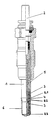
- the single figure shows the embodiment of the invention Glow plug in an axial partial sectional view.
- the embodiment of the glow plug according to the invention shown in the drawing comprises a housing in which a heating rod 1 is arranged, which consists of an inner pole 2 for connection to the electrical power supply and a glow tube 5, in which a heating element 3 is arranged, which has the inner pole 2 is electrically connected.
- the glow tube 5 has at least in the area in which the heating element 3 is provided, in particular at its tip, a coating 6 made of a material selected from a group of materials, the NiCrAlY, CoCrAlY, CoNiCrAlY, NiCrAl, NiCr, NiCrFe and NiCrWCo includes.
- This protective coating can consist, for example, of Ni 22Cr 10Al 1Y.
- the coating 6, which is applied directly to the glow tube 5, has a thickness between 10 and 50 ⁇ m, in particular between 20 and 30 ⁇ m.
- the glow tube 5 can consist of the alloys conventionally used hitherto, such as Inconel 600 or 601, but with a low wall thickness over its entire length or at its tip, or of another, in particular less expensive, alloy.
- a suitable heating rod or glow tube shape is provided with a geometry in which edges, corners and sharp transitions are avoided and rounded.
- R1 denotes a place where there is no coating.
- the entire heating rod tip has a radius of about 1 - 5 mm between R1 and R2.
- the radius R3 is approximately 3 to 5 mm.
Landscapes
- Engineering & Computer Science (AREA)
- Chemical & Material Sciences (AREA)
- Combustion & Propulsion (AREA)
- Mechanical Engineering (AREA)
- General Engineering & Computer Science (AREA)
- Resistance Heating (AREA)
- Investigating, Analyzing Materials By Fluorescence Or Luminescence (AREA)
- Fats And Perfumes (AREA)
- Orthopedics, Nursing, And Contraception (AREA)
- Liquid Crystal Substances (AREA)
- Finger-Pressure Massage (AREA)
Abstract
Description
- Die Erfindung betrifft eine Glühkerze nach dem Gattungsbegriff des Patentanspruchs 1.
- Eine derartige Glühkerze, die beispielsweise aus der DE-OS 41 33 338 bekannt ist, kann in Form einer Stabglühkerze ausgebildet sein und dient z. B. als Starthilfe für eine luftverdichtende Brennkraftmaschine.
- Glühkerzen werden darüber hinaus auch zur Zündungsunterstützung bei Heizgeräten eingesetzt.
- Das Problem bei den bisher üblichen bekannten Glühkerzen dieser Art besteht darin, daß sie den künftigen Anforderungen an eine kurze Aufheizzeit nicht genügen, oder aber die Verkürzung der Aufheizzeit mit einer Verringerung der Lebensdauer der Glühkerze erkauft werden muß.
- Die der Erfindung zugrundliegende Aufgabe besteht daher drin, eine Glühkerze der eingangs genannten Art zu schaffen, die eine kurze Aufheizzeit und eine lange Lebensdauer hat.
- Diese Aufgabe wird gemäß der Erfindung durch die Ausbildung gelöst, die im Kennzeichen des Patentanspruchs 1 angegeben ist.
- Die gemäß der Erfindung vorgesehene Beschichtung wirkt als Oberflächenschutz des Glührohres, so daß dessen Wandstärke erheblich verringert werden kann. Die dadurch erzielte geringere Masse hat zur Folge, daß die erfindungsgemäße Glühkerze eine kurze Aufheizzeit, d. h. eine schnelle Aufheizung zeigt, wodurch eine schnellere Startbereitschaft bei Dieselfahrzeugen erreicht werden kann, deren Maschine mit derartigen Glühkerzen ausgerüstet ist. Dabei wird die extrem schnelle Aufheizzeit ohne Beeinträchtigung der Lebensdauer der Glühkerze erzielt.
- Die erfindungsgemäße Ausbildung hat weiterhin den Vorteil, daR ein Abzundern des Materials des Glührohrs bei den erzielten kurzen Aufheizzeiten, einem langen Nachglühen und hohen Temperaturen vermieden wird, wodurch der Einsatz von Glührohren aus einem Material möglich wird, was mit geringen Kosten verbunden ist. Eine Kostenersparnis ergibt sich darüber hinaus dadurch, daß das Glührohr geringere Rohrwandstärken haben kann.
- Durch die gemäß der Erfindung vorgesehene Beschichtung wird darüber hinaus durch die Porosität die Glührohroberfläche vergrößert und damit die Wärmeabstrahlung verbessert. Es ergibt sich eine gleichmäßigere Temperaturverteilung und eine bessere Aufbereitung der auftreffenden Kraftstoffteilchen.
- Besonders bevorzugte Weiterbildungen und Ausgestaltungen der erfindungsgemäßen Glühkerze sind Gegenstand der Ansprüche 2 und 3.
- Im folgenden wird anhand der zugehörigen Zeichnung ein besonders bevorzugtes Ausführungsbeispiel der Erfindung näher beschrieben.
- Die einzige Figur zeigt das Ausführungsbeispiel der erfindungsgemäßen Glühkerze in einer axialen Teilschnittansicht.
- Das in der Zeichnung dargestellte Ausführungsbeispiel der erfindungsgemäßen Glühkerze umfaßt ein Gehäuse, in dem ein Heizstab 1 angeordnet ist, der aus einem Innenpol 2 zum Anschluß an die elektrische Energieversorgung und einem Glührohr 5 besteht, in dem ein Heizelement 3 angeordnet ist, das mit dem Innenpol 2 elektrisch verbunden ist. Das Heizelement 3, das aus einer Heiz- und einer Regelwendel bestehen kann, von denen die Regelwendel mit dem Innenpol 2 verbunden ist, ist in eine MgO-Füllung 4 im Glührohr 5 eingebettet.
- Das Glührohr 5 weist wenigstens in dem Bereich, in dem das Heizelement 3 vorgesehen ist, insbesondere an seiner Spitze eine Beschichtung 6 aus einem Material auf, das aus einer Materialgruppe gewählt ist, die NiCrAlY, CoCrAlY, CoNiCrAlY, NiCrAl, NiCr, NiCrFe und NiCrWCo umfaßt. Diese Schutzbeschichtung kann beispielsweise aus Ni 22Cr 10Al 1Y bestehen.
- Die Beschichtung 6, die direkt auf das Glührohr 5 aufgebracht ist, hat eine Dicke zwischen 10 und 50 µm, insbesondere zwischen 20 und 30 µm.
- Bei einer derartigen Ausbildung kann das Glührohr 5 aus den bisher üblicherweise verwendeten Legierungen, wie beispielsweise Inconel 600 oder 601, allerdings mit einer niedrigen Wandstärke über seine gesamte Länge oder an seiner Spitze oder aus einer anderen insbesondere kostengünstigeren Legierung bestehen.
- Bei einer dünneren Wandung des Glührohres 5 wird eine schnellere Wärmeübertragung vom Heizelement 3 zur Glührohroberfläche erreicht, wobei durch die Beschichtung das Glührohr 5 vor einer Verzunderung geschützt ist.
- Um eine ausreichende Haftung der Beschichtung über die gesamte Lebensdauer der Glühkerze sicherzustellen, ist eine geeignete Heizstab- oder Glührohrform mit einer Geometrie vorgesehen, bei der Kanten, Ecken und scharfe Übergänge vermieden und abgerundet sind. In der Zeichnung bezeichnet R1 eine Stelle, an der keine Beschichtung vorhanden ist. Bei einer Beschichtung der ganzen Heizstabspitze ist zwischen R1 und R2 ein Radius von etwa 1 - 5 mm vorgesehen. Der Radius R3 beträgt demgegenüber etwa 3 bis 5 mm.
- Aufgrund der möglichen geringeren Rohrwandstärke des Glührohres 5 und dem erzielten gleichbleibenden Aufheizverhalten kann der Energiebedarf der Glühkerze erheblich gesenkt werden, was das Heizelement 3 schont. Dabei sind niedrigere Heizstabendtemperaturen aufgrund der erzielten größeren Oberfläche möglich und ergibt sich eine Annäherung an Keramikkerzen.
Claims (3)
- Glühkerze mit einem Heizstab aus einem Innenpol und einem Glührrohr, in dem ein Heizelement angeordnet ist, das mit dem Innenpol elektrisch verbunden ist, dadurch gekennzeichnet, daß das Glührohr wenigstens in dem Bereich, in dem das Heizelement angeordnet ist, mit einer Beschichtung aus einem Material versehen ist, das aus einer Materialgruppe gewählt ist, die NiCrAlY, CoCrAlY, CoNiCrAlY, NiCrAl, NiCr, NiCrFe und NiCrWCo umfaßt.
- Glühkerze nach Anspruch 1, dadurch gekennzeichnet, daß die Dicke der Beschichtung 10 bis 50 µm beträgt.
- Glühkerze nach Anspruch 2, dadurch gekennzeichnet, daß die Dicke der Beschichtung 20 bis 30µm beträgt.
Applications Claiming Priority (2)
| Application Number | Priority Date | Filing Date | Title |
|---|---|---|---|
| DE19511376A DE19511376A1 (de) | 1995-03-28 | 1995-03-28 | Glühkerze |
| DE19511376 | 1995-03-28 |
Publications (3)
| Publication Number | Publication Date |
|---|---|
| EP0735323A2 true EP0735323A2 (de) | 1996-10-02 |
| EP0735323A3 EP0735323A3 (de) | 1998-02-18 |
| EP0735323B1 EP0735323B1 (de) | 2003-02-05 |
Family
ID=7757971
Family Applications (1)
| Application Number | Title | Priority Date | Filing Date |
|---|---|---|---|
| EP96103902A Expired - Lifetime EP0735323B1 (de) | 1995-03-28 | 1996-03-12 | Glühkerze |
Country Status (8)
| Country | Link |
|---|---|
| US (1) | US5626781A (de) |
| EP (1) | EP0735323B1 (de) |
| JP (1) | JPH08278027A (de) |
| KR (1) | KR100416730B1 (de) |
| AT (1) | ATE232286T1 (de) |
| BR (1) | BR9601148A (de) |
| DE (2) | DE19511376A1 (de) |
| ES (1) | ES2188683T3 (de) |
Families Citing this family (9)
| Publication number | Priority date | Publication date | Assignee | Title |
|---|---|---|---|---|
| US6076493A (en) * | 1998-10-26 | 2000-06-20 | Caterpillar Inc. | Glow plug shield with thermal barrier coating and ignition catalyst |
| DE19920766C1 (de) * | 1999-05-05 | 2000-12-21 | Beru Ag | Glühkerze und Verfahren zur Herstellung derselben |
| US6215105B1 (en) * | 1999-08-18 | 2001-04-10 | Delphi Technologies, Inc. | Ion sensor glow plug assembly with coating between sheath and shell |
| US6285007B1 (en) * | 1999-08-18 | 2001-09-04 | Delphi Technologies, Inc. | Ion sensor glow plug assembly |
| US6465759B1 (en) * | 2000-03-14 | 2002-10-15 | Delphi Technologies, Inc. | Ion sensor glow plug assembly |
| US6512204B1 (en) * | 2000-03-14 | 2003-01-28 | Delphi Technologies, Inc. | Ion sensor glow plug assembly |
| DE102005024622B4 (de) * | 2005-05-30 | 2007-10-04 | Beru Ag | Stabglühkerze |
| US8869739B2 (en) | 2011-10-28 | 2014-10-28 | General Electric Company | Wheel coating method and apparatus for a turbine |
| JP6996848B2 (ja) * | 2017-02-03 | 2022-01-17 | 日本特殊陶業株式会社 | グロープラグ |
Citations (3)
| Publication number | Priority date | Publication date | Assignee | Title |
|---|---|---|---|---|
| JPS6022075A (ja) * | 1983-07-16 | 1985-02-04 | Toyota Motor Corp | 副燃焼室式デイ−ゼルエンジン |
| DE8815005U1 (de) * | 1988-12-02 | 1990-03-29 | Robert Bosch Gmbh, 7000 Stuttgart, De | |
| DE9315442U1 (de) * | 1993-10-12 | 1993-12-23 | Beru Werk Ruprecht Gmbh Co A | Glühkerze |
Family Cites Families (8)
| Publication number | Priority date | Publication date | Assignee | Title |
|---|---|---|---|---|
| GB927336A (en) * | 1960-10-14 | 1963-05-29 | Wilkinson Sword Ltd | Improvements in or relating to igniting devices |
| JPS57155025A (en) * | 1981-03-20 | 1982-09-25 | Hitachi Ltd | Quick heating type glow plug for diesel engine |
| JPS58123025A (ja) * | 1982-01-18 | 1983-07-22 | Ngk Spark Plug Co Ltd | シ−ズグロ−プラグおよびその製造法 |
| JPS58150715A (ja) * | 1982-03-02 | 1983-09-07 | Nippon Denso Co Ltd | デイ−ゼルエンジンの予熱栓 |
| JPS59167735A (ja) * | 1983-03-14 | 1984-09-21 | Oki Electric Ind Co Ltd | カナ漢字変換装置 |
| US4746896A (en) * | 1986-05-08 | 1988-05-24 | North American Philips Corp. | Layered film resistor with high resistance and high stability |
| JPH04263702A (ja) * | 1991-02-18 | 1992-09-18 | Hino Motors Ltd | グロープラグ |
| JPH04288410A (ja) * | 1991-03-15 | 1992-10-13 | Hino Motors Ltd | メタノールエンジン用グロープラグ |
-
1995
- 1995-03-28 DE DE19511376A patent/DE19511376A1/de not_active Withdrawn
-
1996
- 1996-03-12 DE DE59610102T patent/DE59610102D1/de not_active Expired - Fee Related
- 1996-03-12 AT AT96103902T patent/ATE232286T1/de not_active IP Right Cessation
- 1996-03-12 ES ES96103902T patent/ES2188683T3/es not_active Expired - Lifetime
- 1996-03-12 EP EP96103902A patent/EP0735323B1/de not_active Expired - Lifetime
- 1996-03-20 KR KR1019960007586A patent/KR100416730B1/ko not_active IP Right Cessation
- 1996-03-27 JP JP8099038A patent/JPH08278027A/ja active Pending
- 1996-03-27 BR BR9601148A patent/BR9601148A/pt not_active IP Right Cessation
- 1996-03-28 US US08/623,217 patent/US5626781A/en not_active Expired - Lifetime
Patent Citations (3)
| Publication number | Priority date | Publication date | Assignee | Title |
|---|---|---|---|---|
| JPS6022075A (ja) * | 1983-07-16 | 1985-02-04 | Toyota Motor Corp | 副燃焼室式デイ−ゼルエンジン |
| DE8815005U1 (de) * | 1988-12-02 | 1990-03-29 | Robert Bosch Gmbh, 7000 Stuttgart, De | |
| DE9315442U1 (de) * | 1993-10-12 | 1993-12-23 | Beru Werk Ruprecht Gmbh Co A | Glühkerze |
Non-Patent Citations (1)
| Title |
|---|
| PATENT ABSTRACTS OF JAPAN vol. 009, no. 142 (M-388), 18.Juni 1985 & JP 60 022075 A (TOYOTA JIDOSHA KK), 4.Februar 1985, * |
Also Published As
| Publication number | Publication date |
|---|---|
| BR9601148A (pt) | 1998-01-06 |
| KR960034719A (ko) | 1996-10-24 |
| JPH08278027A (ja) | 1996-10-22 |
| EP0735323A3 (de) | 1998-02-18 |
| EP0735323B1 (de) | 2003-02-05 |
| ES2188683T3 (es) | 2003-07-01 |
| DE59610102D1 (de) | 2003-03-13 |
| DE19511376A1 (de) | 1996-10-02 |
| ATE232286T1 (de) | 2003-02-15 |
| US5626781A (en) | 1997-05-06 |
| KR100416730B1 (ko) | 2004-04-17 |
Similar Documents
| Publication | Publication Date | Title |
|---|---|---|
| DE2802625C3 (de) | Glühkerze | |
| DE69819583T2 (de) | Keramischer Heizer | |
| DE4133046C2 (de) | Selbstregelnde Glühkerze | |
| EP0673493B1 (de) | Glühkerze | |
| EP0505368B1 (de) | Verfahren zur herstellung von elektroden für zündkerzen sowie zündkerzen-elektroden | |
| DE3421950A1 (de) | Selbstregelnde gluehkerze | |
| DE3825013A1 (de) | Gluehkerze | |
| EP0735323B1 (de) | Glühkerze | |
| EP0151122B1 (de) | Einrichtung zum einspritzen von kraftstoff in brennräume | |
| DE3434762C2 (de) | ||
| EP0078954B1 (de) | Zündkerze für Brennkraftmaschinen | |
| EP0607592A2 (de) | Stabflammglühkerze | |
| EP0392180B1 (de) | Glühstiftkerze | |
| EP0103775B1 (de) | Glühkerze für Brennkraftmaschinen | |
| DE3301559A1 (de) | Stabgluehkerze fuer eine luftverdichtende einspritzbrennkraftmaschine | |
| DE3003799A1 (de) | Gluehkerze fuer brennkraftmaschinen | |
| EP0392181B1 (de) | Glühstiftkerze | |
| DE3429262A1 (de) | Gluehzuender | |
| DE10004313B4 (de) | Dieselkraftstoff-Einspritzdüse | |
| DE102013104992A1 (de) | Glühkerze | |
| DE102020103863B4 (de) | Fremd gezündete Hubkolben-Brennkraftmaschine mit einem Vorkammerzündsystem | |
| DE4310821C2 (de) | Lichtbogen-Strahltriebwerk | |
| WO1999027302A1 (de) | Glühstiftkerze für brennkraftmaschinen | |
| DE2516727C3 (de) | Zündkerzen-Elektrode | |
| DE1948588A1 (de) | Zuendkerze |
Legal Events
| Date | Code | Title | Description |
|---|---|---|---|
| PUAI | Public reference made under article 153(3) epc to a published international application that has entered the european phase |
Free format text: ORIGINAL CODE: 0009012 |
|
| AK | Designated contracting states |
Kind code of ref document: A2 Designated state(s): AT DE ES FR GB IT NL SE |
|
| PUAL | Search report despatched |
Free format text: ORIGINAL CODE: 0009013 |
|
| AK | Designated contracting states |
Kind code of ref document: A3 Designated state(s): AT DE ES FR GB IT NL SE |
|
| 17P | Request for examination filed |
Effective date: 19980608 |
|
| RAP1 | Party data changed (applicant data changed or rights of an application transferred) |
Owner name: BERU RUPRECHT AG |
|
| RAP1 | Party data changed (applicant data changed or rights of an application transferred) |
Owner name: BERU AG |
|
| 17Q | First examination report despatched |
Effective date: 19991029 |
|
| GRAG | Despatch of communication of intention to grant |
Free format text: ORIGINAL CODE: EPIDOS AGRA |
|
| GRAG | Despatch of communication of intention to grant |
Free format text: ORIGINAL CODE: EPIDOS AGRA |
|
| GRAH | Despatch of communication of intention to grant a patent |
Free format text: ORIGINAL CODE: EPIDOS IGRA |
|
| GRAH | Despatch of communication of intention to grant a patent |
Free format text: ORIGINAL CODE: EPIDOS IGRA |
|
| GRAA | (expected) grant |
Free format text: ORIGINAL CODE: 0009210 |
|
| AK | Designated contracting states |
Designated state(s): AT DE ES FR GB IT NL SE |
|
| REG | Reference to a national code |
Ref country code: GB Ref legal event code: FG4D Free format text: NOT ENGLISH |
|
| REF | Corresponds to: |
Ref document number: 59610102 Country of ref document: DE Date of ref document: 20030313 Kind code of ref document: P |
|
| REG | Reference to a national code |
Ref country code: SE Ref legal event code: TRGR |
|
| GBT | Gb: translation of ep patent filed (gb section 77(6)(a)/1977) | ||
| REG | Reference to a national code |
Ref country code: ES Ref legal event code: FG2A Ref document number: 2188683 Country of ref document: ES Kind code of ref document: T3 |
|
| ET | Fr: translation filed | ||
| PLBE | No opposition filed within time limit |
Free format text: ORIGINAL CODE: 0009261 |
|
| STAA | Information on the status of an ep patent application or granted ep patent |
Free format text: STATUS: NO OPPOSITION FILED WITHIN TIME LIMIT |
|
| 26N | No opposition filed |
Effective date: 20031106 |
|
| PG25 | Lapsed in a contracting state [announced via postgrant information from national office to epo] |
Ref country code: IT Free format text: LAPSE BECAUSE OF NON-PAYMENT OF DUE FEES Effective date: 20050312 |
|
| PGFP | Annual fee paid to national office [announced via postgrant information from national office to epo] |
Ref country code: FR Payment date: 20050316 Year of fee payment: 10 |
|
| PGFP | Annual fee paid to national office [announced via postgrant information from national office to epo] |
Ref country code: ES Payment date: 20060303 Year of fee payment: 11 |
|
| PGFP | Annual fee paid to national office [announced via postgrant information from national office to epo] |
Ref country code: AT Payment date: 20060309 Year of fee payment: 11 |
|
| PGFP | Annual fee paid to national office [announced via postgrant information from national office to epo] |
Ref country code: NL Payment date: 20060310 Year of fee payment: 11 Ref country code: GB Payment date: 20060310 Year of fee payment: 11 |
|
| PG25 | Lapsed in a contracting state [announced via postgrant information from national office to epo] |
Ref country code: SE Free format text: LAPSE BECAUSE OF NON-PAYMENT OF DUE FEES Effective date: 20070313 |
|
| EUG | Se: european patent has lapsed | ||
| PG25 | Lapsed in a contracting state [announced via postgrant information from national office to epo] |
Ref country code: AT Free format text: LAPSE BECAUSE OF NON-PAYMENT OF DUE FEES Effective date: 20070312 |
|
| GBPC | Gb: european patent ceased through non-payment of renewal fee |
Effective date: 20070312 |
|
| NLV4 | Nl: lapsed or anulled due to non-payment of the annual fee |
Effective date: 20071001 |
|
| REG | Reference to a national code |
Ref country code: FR Ref legal event code: ST Effective date: 20071130 |
|
| PG25 | Lapsed in a contracting state [announced via postgrant information from national office to epo] |
Ref country code: NL Free format text: LAPSE BECAUSE OF NON-PAYMENT OF DUE FEES Effective date: 20071001 |
|
| PGFP | Annual fee paid to national office [announced via postgrant information from national office to epo] |
Ref country code: SE Payment date: 20060310 Year of fee payment: 11 |
|
| PG25 | Lapsed in a contracting state [announced via postgrant information from national office to epo] |
Ref country code: GB Free format text: LAPSE BECAUSE OF NON-PAYMENT OF DUE FEES Effective date: 20070312 |
|
| REG | Reference to a national code |
Ref country code: ES Ref legal event code: FD2A Effective date: 20070313 |
|
| PG25 | Lapsed in a contracting state [announced via postgrant information from national office to epo] |
Ref country code: FR Free format text: LAPSE BECAUSE OF NON-PAYMENT OF DUE FEES Effective date: 20070402 Ref country code: ES Free format text: LAPSE BECAUSE OF NON-PAYMENT OF DUE FEES Effective date: 20070313 |
|
| PG25 | Lapsed in a contracting state [announced via postgrant information from national office to epo] |
Ref country code: FR Free format text: LAPSE BECAUSE OF NON-PAYMENT OF DUE FEES Effective date: 20060331 |
|
| PGFP | Annual fee paid to national office [announced via postgrant information from national office to epo] |
Ref country code: DE Payment date: 20090331 Year of fee payment: 14 |
|
| PG25 | Lapsed in a contracting state [announced via postgrant information from national office to epo] |
Ref country code: DE Free format text: LAPSE BECAUSE OF NON-PAYMENT OF DUE FEES Effective date: 20101001 |