EP0734149B1 - Procédé de traitement de données d'image - Google Patents
Procédé de traitement de données d'image Download PDFInfo
- Publication number
- EP0734149B1 EP0734149B1 EP96104281A EP96104281A EP0734149B1 EP 0734149 B1 EP0734149 B1 EP 0734149B1 EP 96104281 A EP96104281 A EP 96104281A EP 96104281 A EP96104281 A EP 96104281A EP 0734149 B1 EP0734149 B1 EP 0734149B1
- Authority
- EP
- European Patent Office
- Prior art keywords
- threshold
- data
- positions
- image data
- determined
- Prior art date
- Legal status (The legal status is an assumption and is not a legal conclusion. Google has not performed a legal analysis and makes no representation as to the accuracy of the status listed.)
- Expired - Lifetime
Links
Images


Classifications
-
- H—ELECTRICITY
- H04—ELECTRIC COMMUNICATION TECHNIQUE
- H04N—PICTORIAL COMMUNICATION, e.g. TELEVISION
- H04N1/00—Scanning, transmission or reproduction of documents or the like, e.g. facsimile transmission; Details thereof
- H04N1/40—Picture signal circuits
- H04N1/405—Halftoning, i.e. converting the picture signal of a continuous-tone original into a corresponding signal showing only two levels
- H04N1/4051—Halftoning, i.e. converting the picture signal of a continuous-tone original into a corresponding signal showing only two levels producing a dispersed dots halftone pattern, the dots having substantially the same size
- H04N1/4052—Halftoning, i.e. converting the picture signal of a continuous-tone original into a corresponding signal showing only two levels producing a dispersed dots halftone pattern, the dots having substantially the same size by error diffusion, i.e. transferring the binarising error to neighbouring dot decisions
-
- H—ELECTRICITY
- H04—ELECTRIC COMMUNICATION TECHNIQUE
- H04N—PICTORIAL COMMUNICATION, e.g. TELEVISION
- H04N1/00—Scanning, transmission or reproduction of documents or the like, e.g. facsimile transmission; Details thereof
- H04N1/40—Picture signal circuits
- H04N1/405—Halftoning, i.e. converting the picture signal of a continuous-tone original into a corresponding signal showing only two levels
- H04N1/4051—Halftoning, i.e. converting the picture signal of a continuous-tone original into a corresponding signal showing only two levels producing a dispersed dots halftone pattern, the dots having substantially the same size
Definitions
- the present invention relates to a method of processing multivalued image data by converting the multivalued image data into binary image data to produce a halftone dot image.
- output devices typically laser printers
- output devices for converting multivalued image data into binary image data using predetermined threshold data, and selectively turning on and off a laser beam based on the produced binary image data thereby to form a halftone dot image with gradations on an output medium.
- gradations of tone of halftone dot images can be expressed by either one of two processes.
- One of the processes is referred to as an amplitude modulation process (AM process) by which the size of dots or pixels is modulated according to multivalued image data.
- AM process amplitude modulation process
- FM process frequency modulation process
- the size of dots remains unchanged, but the density of dots is modulated according to multivalued image data.
- the error distributing process when multivalued image data are to be converted into binary image data using predetermined threshold data, errors produced between the multivalued image data and the binary image data are distributed into surrounding pixels, generating binary image data having desired densities.
- the threshold process multivalued image data are converted into binary image data using threshold data that are established as a dither matrix.
- a conventional threshold process employs a distributed dither matrix (known as a Bayer's dither matrix) corresponding to each region of an image that is divided into a plurality of blocks. This conventional threshold process tends to allow undesirable regular patterns to be visually noticed in a reproduced halftone dot image.
- a distributed dither matrix known as a Bayer's dither matrix
- the conventional threshold process is also disadvantageous in that since it does not take into account the effect of a dot gain of an output device or medium for outputting an image, a halftone dot image reproduced by the conventional threshold process is degraded if the dot gain is large.
- a laser beam in a laser printer used as an output device for forming a halftone dot image has a beam spot which is either circular or elliptical in shape, and the laser intensity of the beam spot is of a normal distribution. Consequently, the laser beam is liable to blur surrounding pixels that are recorded, failing to reproduce accurate gradations of tone in a halftone dot image.
- An output medium on which a halftone dot image is to be reproduced also has a dot gain such as blurring of a blackened area and blurring of an ink, causing gradation errors.
- a dither matrix comprises an array of numbers arranged in rows and columns, and the numbers arrayed in the direction of either rows or columns are greater than the numbers arrayed in the other direction of columns or rows.
- the numbers arrayed in the other direction are rearranged randomly in each of blocks into which an image is divided. In this manner, an undesirable regular pattern produced by the repetition of the dither matrix is made less visually recognizable, and the storage capacity of a memory for storing the dither matrix is reduced.
- the disclosed method is unable to completely eliminate the regular pattern, and cannot avoid an image degradation due to a dot gain depending on an output device used, as with the process using the Bayer's dither matrix.
- the disclosed method is more time-consuming than the process using the Bayer's dither matrix because it is necessary to rearrange repeatedly the numbers arrayed in the other direction.
- Japanese laid-open patent publication No. 5-3540 reveals one error distributing process in which when multivalued image data are to be converted into binary image data, a dot generating pattern (binarizing pattern) is determined in advance with respect to those pixels which surround a pixel in question, an error caused by the binarizing process is corrected using a corrective value corresponding to the dot generating pattern which is stored in a pattern table memory, and the corrected error is used as a new error for error distribution.
- the proposed process is capable of establishing accurate corrective values with respect to ideal dot generating patterns such as a circular dot generating pattern, and hence of reproducing good images with those ideal dot generating patterns.
- this process is applicable to not all output devices and output mediums which have output characteristics and various dot gain characteristics depending on beam spot configurations, etc.
- the proposed process requires a considerable processing time because it is an error distributing process.
- a major object of the present invention is to determine the positions of thresholds in a sequence to maximize the distance between those positions in a threshold matrix for increasing the spatial frequency of an error which is caused when multivalued image data are converted into binary image data using the threshold matrix, and also to take into account the positions of thresholds in surrounding threshold matrixes in determining the positions of thresholds in the threshold matrix, for thereby reducing the visibility of a periodic pattern produced by a repetition of threshold matrixes.
- Another object of the present invention is to use a point spread function produced in view of visual characteristics as a weighting filter and successively determine the positions of thresholds in order to minimize the variation of a weighting distribution which is produced by causing the weighting filter to act primarily on the positions of thresholds that have already been determined, for thereby producing a threshold matrix capable of reducing the visibility of an undesirable granularity in a produced image.
- Still another object of the present invention is to determine thresholds in view of surrounding threshold matrixes for thereby reducing the visibility of a periodic pattern produced by discrete surrounding thresholds .
- Yet still another object of the present invention is to determine the positions of thresholds in view of the distances between the thresholds in highlight and shadow regions of thresholds, and determine the positions of thresholds using predetermined weighting filters in an intermediate region of thresholds, for thereby producing a threshold matrix for making any granularity and periodic patterns less visually recognizable in the entire range of a produced image.
- a further object of the present invention is to generate test patterns using an output device or an output medium which is actually used, measure the densities or halftone dot area percentages of the test patterns, determine effective gradation incremental data from the differences between the measured densities or halftone dot area percentages and an ideal density or an ideal halftone dot area percentage, and convert multivalued image data into binary image data using the gradation incremental data for thereby generating a highly accurate gradation data in view of gradation increases due to surrounding pixels.
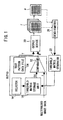
- FIG. 1 shows in block form a system to which a method of processing image data according to the present invention is applied.
- Multivalued image data I inputted from an external device to a raster image processor (RIP) 10 are supplied to a comparator 12.
- the comparator 12 compares the supplied multivalued image data I with threshold data TH which have been selected by a selector 14 based on output conditions including a screen ruling, an output medium, etc. and outputted from a threshold matrix storage unit 16, and converts the multivalued image data I into binary image data B.
- the threshold data TH are generated by a threshold matrix generator 22 in a manner described later on.
- the threshold matrix generator 22 may be integrally combined with the raster image processor 10.
- the binary image data B are supplied to an output device 20 such as a laser printer.
- the output device 20 Based on the supplied binary image data B, the output device 20 selectively turns on and off a laser beam to form a halftone dot image on a photographic film F, producing an original film plate. From the original film plate, there is produced a printing plate which is then set in a printing press (not shown) to form a desired printed document P that comprises a printing sheet as a recording medium with a halftone dot image formed thereon.
- thresholds ranging from 1 to 25 are established in the threshold matrixes.
- the principles of the present invention are also applicable to establishing thresholds in any desired numerical range in threshold matrixes.
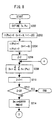
- FIGS. 2 through 4 are flowcharts of a processing sequence of a method of processing image data according to a first embodiment of the present invention.
- threshold matrixes are generated such that thresholds having close values are not positioned closely to each other, so that halftone dots of an image which is formed by the threshold matrixes are not unduly localized, thus lowering the granularity of a reproduced halftone dot image.
- the thresholds in a threshold matrix are arranged in view of other threshold matrixes established adjacent thereto for thereby preventing a regular pattern from being produced by a repetition of threshold matrixes.
- the thresholds t(P k1 ) have x coordinates x k1 and y coordinates y k1 .
- pixel points P k1 whose thresholds t(P k1 ) are to be set to 3 through 25 are determined as follows:
- the minimum value Rmin (i) can be determined according to a flowchart shown in FIG. 4.
- steps S152, S154, S156, S158, S160, S162 are carried out, and then a pixel point P k1 whose threshold t(P k1 ) is set to other than 0 is extracted in a step S164.
- the distance RR thus determined and the minimum value Rmin (i) are compared with each other in a step S168. If RR ⁇ Rmin (i), then the minimum value Rmin (i) is set to the distance RR in a step S170.
- the above process is effected on all the pixel points P k1 whose thresholds t(P k1 ) are not 0, thereby determining the minimum value Rmin (i) of the distances between the pixel point P 5i and surrounding pixel points P k1 whose thresholds t(P k1 ) have already been established.
- variable i is incremented in the step S116, a minimum value Rmin (i) is determined again in the step S122, and the minimum value Rmin (i) and a maximum value Rmax updated in the step S126 are compared with each other in the steps S124, S130.
- Rmin (i) Rmax in the step S130, then there are two or more pixel points P 5i that are spaced by equal distances from the pixel points P k1 whose thresholds t(P k1 ) have already been established, as shown in FIG. 6.
- two pixel points P 5i whose thresholds t(P 5i ) are indicated by 3A, 3B in FIG. 6.
- a random number NEWRND which can have a value of either 0 or 1 is determined in a step S132, and compared with the random number RND established in the step S112 in a step S134.
- RND NEWRND
- the step S108 is repeated, and thresholds t(P k1 ) are set to 4 ⁇ 25, thereby establishing the thresholds t(P k1 ) with respect to all the pixel points P k1 in the threshold arrays T k in a step S110.
- threshold arrays T k thus determined, only the threshold array T 5 is extracted and stored as a threshold matrix in the threshold matrix storage unit 16 shown in FIG. 1.
- the selector 14 selects the threshold matrix (threshold array T 5 ) from the threshold matrix storage unit 16, and supplies its threshold data TH (corresponding to the threshold t(P 5l )) to the comparator 12.
- the comparator 12 compares the supplied threshold data TH with the multivalued image data I, thereby generating binary image data B.
- the binary image data B are outputted as a halftone dot image on a photographic film F by the output device 20, and a printed document P is produced from the photographic film F.
- the threshold matrixes are generated such that thresholds having close values are not positioned closely to each other, halftone dots of an image which is formed by the threshold matrixes are not unduly localized. Therefore, it is possible to produce a halftone dot image with a reduced degree of granularity.
- the thresholds are arranged in view of other surrounding threshold matrixes such as the threshold arrays T 1 ⁇ T 4 , T 6 ⁇ T 9 shown in FIG. 5. Accordingly, a halftone dot image is of a good quality, free of a regular pattern which would otherwise be produced by a repetition of threshold matrixes.
- a threshold t(P k1 ) is set to successive numerical values in an ascending order, e.g., it is set successively to 1, 2, ⁇ .
- a threshold t(P k1 ) is to be set to a large numerical value, since the thresholds t(P k1 ) of most pixel points P k1 have already been established, mutually close pixel points P k1 may have to be selected.
- a pixel point P k3 for which a threshold t(P k3 ) is set to 3 is determined, after which a pixel point P k23 for which a threshold t(P k23 ) is set to 23 is determined.
- thresholds P k1 are set alternately, one by one, to numerical values from highlight and shadow regions, thereby establishing a threshold array T 5 .
- the thresholds P k1 set to numerical values from highlight and shadow regions are sufficiently spaced from each other. Consequently, when a halftone dot image is generated using a threshold matrix which comprises the threshold array T 5 , the generated halftone dot image is of a good quality, free from harshness in both the highlight and shadow regions.
- FIGS. 8 and 9 are illustrative of a method of processing image data according to a third embodiment of the present invention.
- visual spatial frequency characteristics (MTF) shown in FIG. 15 are subjected to a two-dimensional Fourier transform to determine a visual point spread function shown in FIG. 10, and the visual point spread function is caused to act on positions corresponding to the positions of thresholds to effect accumulative addition or subtraction of weighted values for thereby determining a hypothetical distribution of densities of an image produced by the thresholds.
- threshold matrixes By establishing threshold matrixes in order to minimize the variation of the hypothetical distribution of densities, an unwanted granularity is reduced.
- the thresholds in the threshold matrix are arranged in view of other threshold matrixes established adjacent to the threshold matrix for thereby preventing a regular pattern from being produced by a discrete repetition of threshold matrixes.
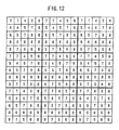
- the weighting filter f kl (P kz ) shown in FIG. 11 is a representation of the distribution of the visual point spread function shown in FIG. 10 as a two-dimensional density distribution that comprises a 5 ⁇ 5 matrix.
- the weighting filter f kl (P kz ) is caused to act mainly on the pixel points P kl of the threshold arrays T k for which the thresholds t(P kl ) are established, and the weighted values are added to produce a density distribution D kl shown in FIG. 12.
- the thresholds t(P kl ) By successively establishing the thresholds t(P kl ) to minimize the variation of the density distribution D kl , i.e., to achieve the minimum value thereof in this case, any undesirable granularity can be minimized.
- steps S224 ⁇ S238 which are the same as the steps S124 ⁇ S138 in the first embodiment shown in FIG. 3 are carried out to extract a pixel point P 5z (corresponding to the position of a numeral 4) of the lowest density from the density distribution D kl shown in FIG. 12.
- the step S208 is repeated, and thresholds t(P kl ) are set to 4 ⁇ 25, thereby establishing the thresholds t(P kl ) with respect to all the pixel points P kl in the threshold arrays T k in a step S212.
- the threshold arrays T k thus determined, only the threshold array T 5 is extracted and stored as a threshold matrix in the threshold matrix storage unit 16 shown in FIG. 1, as with the first embodiment.
- the thresholds in the threshold matrixes thus generated are arranged to minimize any undesirable granularity, they can produce a good-quality halftone-dot image. Because the thresholds are arranged in view of other surrounding threshold matrixes, a halftone dot image produced thereby is of a good quality, free of a regular pattern which would otherwise be produced by a repetition of threshold matrixes.
- thresholds P kl may be set alternately, one by one, to numerical values from highlight and shadow regions, for producing a better-quality halftone dot image.
- the density distribution D kl may be determined by accumulative subtraction, rather than accumulative addition, of weighting filters f kl (P kz ).
- the weighting filters f kl (P kz ) depending on the visual perception are of a finite magnitude, and minimum and maximum values may not uniquely be determined even when a density distribution D kl is determined and hence the position of a suitable threshold may not be determined in highlight and shadow regions where thresholds are spaced from each other by a distance greater than a range in which the weighting filters f kl (P kz ) act.
- thresholds t(P kl ) are established by the method according to the first embodiment (see FIGS. 2 and 3) in a highlight region (0 ⁇ t(P kl ) ⁇ TH W ) thereof, by the method according to the third embodiment (see FIGS. 8 and 9) in an intermediate region (TH W ⁇ t(P kl ) ⁇ TH B ) thereof, and by the method according to the first embodiment in a shadow region (TH B ⁇ t(P kl ) ⁇ TH MAX ) thereof.
- the thresholds TH W , TH B , TH MAX are related to each other by the relationship: 0 ⁇ TH W ⁇ TH B ⁇ TH MAX , and the threshold TH MAX represents a maximum value of the thresholds t(P kl ).
- the fourth embodiment it is possible to generate threshold matrixes for producing a halftone dot image with no undesirable granularity and periodic patterns in the entire threshold range from the highlight region to the shadow region.
- thresholds P kl may be set alternately, one by one, to numerical values from the highlight and shadow regions, for producing a better-quality halftone dot image.
- the beam configuration of a laser beam outputted by the output device 20 and the dot gains of output mediums including the photographic film F and the printed document P are taken into consideration when the photographic film F and the printed document P are produced, and the weighting filters f kl (P kz ) in the third embodiment are corrected by a microscopic gradation increase that is brought about depending on the status of surrounding pixels thereby to generate threshold matrixes, so that a halftone dot image with corrected dot gains can be produced.
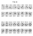
- Test patterns each composed of 3 ⁇ 3 pixels as shown in FIG. 13 are produced on the photographic film F or the printed document P by the output device 20 (see FIG. 1) based on test data T supplied from a test pattern data file 24 in the raster image processor 10. Each of the test patterns is measured for density by a densitometer 26. As shown in FIG. 14, correcting quantities Cor (Q 1 , Q 2 , Q 3 , Q 4 ) are then determined based on density differences with respect to ON (black) and OFF (white) states of surrounding pixels Q 1 , Q 2 , Q 3 , Q 4 when a central pixel Q in question changes from an OFF state to an ON state. Of the nine pixels shown in FIG.
- those four pixels other than the pixels Q, Q 1 , Q 2 , Q 3 , Q 4 are uniformly of an ON or OFF state.
- the pixels Q, Q 1 , Q 2 , Q 3 , Q 4 are represented by 0 when they are of an OFF state, and by 1 when they are of an ON state.
- Densities D1 of the ON/OFF patterns "Q 1 Q 2 Q 3 Q 4 - 1" and densities D2 of the ON/OFF patterns “Q 1 Q 2 Q 3 Q 4 - 2" are measured by the densitometer 26. Then, the threshold matrix generator 22 determines the differences between the densities D1, D2 as dot percentage differences ⁇ (%) between the test patterns.
- the correcting quantities Cor (Q 1 , Q 2 , Q 3 , Q 4 ) thus determined are supplied to the threshold matrix generator 22, which then generates threshold matrixes substantially in the same manner as with the third embodiment.
- the correcting quantities Cor (Q 1 , Q 2 , Q 3 , Q 4 ) for a density pattern in which only those pixels having the thresholds t(P k1 ), t(P k2 ) are blackened on the photographic film F or the printed document P become correcting quantities Cor (0, 0, 0, 0, 0) produced from the test patterns "0000-0" and "0000-1" shown in FIG. 13.
- a weighting filter f kl (P kz ) corrected in view of the dot gains is produced when the elements of the weighting filter f kl (P kz ) are multiplied by 1 + Cor (0, 0, 0, 0, 0).
- weighting filters f kl (P kz ) for pixel points P kl for which thresholds t(P kl ) are established are corrected in view of the dot gains, and the step S208 and following steps shown in FIGS. 8 and 9 are carried out again to generate desired threshold matrixes.
- the threshold matrixes are thus generated depending on the output device 20 and the output mediums, and then stored in the threshold matrix storage unit 16 shown in FIG. 1.
- the selector 14 selects a desired threshold matrix from the threshold matrix storage unit 16, and binary image data B are generated from the multivalued image data I using the selected threshold matrix.
- the binary image data B are then outputted as a halftone dot image on the photographic film F by the output device, and a printed document P is produced from the photographic film F with the halftone dot image recorded thereon.
- the threshold matrixes have been corrected for a microscopic gradation increase due to surrounding pixels in view of the characteristics of the output device depending on the beam spot configuration of the laser beam and the dot gains of the output mediums. Consequently, the halftone dot images on the photographic film F and the printed document P are generated as highly accurate gradation images.
- the thresholds are arranged depending on visual characteristics, it is possible to produce good-quality halftone dot images free from undesirable granularity.
- the thresholds in a threshold matrix are arranged in view of other surrounding threshold matrixes for thereby producing better-quality halftone dot images free from a regular pattern which would be caused by a repetition of threshold matrixes, as with the first embodiment. Inasmuch as the dot gains depending on output mediums including the photographic film F and the printed document D are corrected, it is possible to produce highly accurate halftone dot images with no visually recognizable granularity.
- gradation incremental data are determined by measuring the densities of the test patterns.
- halftone dot area percentages of the test patterns may be measured to determine gradation incremental data.
- a microscopic gradation increase caused under the influence of surrounding pixels is corrected for the generation of threshold matrixes.
- an error distributing process multivalued image data are compared with given threshold data to produce binary image data, and an error caused when the binary image data are produced is taken into account when next binary image data are produced.
- the error may be corrected by the gradation incremental data based on predetermined ON/OFF patterns of surrounding pixels. In this fashion, it is possible to produce halftone dot images having highly accurate gradations by a binarizing process according to the error distributing process.
- thresholds may be set alternately, one by one, to numerical values from highlight and shadow regions, for producing a better-quality halftone dot image.
- test patterns are generated to determine gradation incremental data, as shown in FIG. 13.
- one of horizontally or vertically symmetrical sets of test patterns may be dispensed with, and gradation incremental data may be determined from 8 or 4 test patterns.
- gradation incremental data may be determined from one test pattern.
- thresholds are established in a sequence of distances between pixels which make up a threshold matrix, for producing a good-quality binary image with no localized dots.
- the positions of pixel points of other surrounding threshold matrixes are taken into account, so that the produced binary image is free of a periodic pattern caused by a repetition of threshold matrixes.
- a visual point spread function obtained from visual characteristics is used as a weighting filter, and the weighting filter is caused to act primarily on the positions of thresholds which have already been determined. Thresholds are determined successively from regions where a weighting distribution obtained by accumulative addition or subtraction of weighted values is minimum. With the thresholds thus determined, it is possible to produce a good-quality binary image free from granularity and periodic patterns.
- the positions of thresholds are determined in view of the distances between the thresholds. In an intermediate region of thresholds, the positions of thresholds are determined using predetermined weighting filters. Therefore, any granularity and periodic patterns are less visually recognizable in the entire range of a produced image.
- test patterns are generated using a desired output device or a desired output medium, it is possible to determine highly accurate gradation incremental data depending on output characteristics of the output device such as a recording beam spot configuration or the dot gain thereof.
- threshold data for use in converting multivalued image data into binary image data are generated using such gradation incremental data or an error caused by a binarizing process according to an error distributing process is corrected using such gradation incremental data, it is possible to generate high-quality halftone dot images in view of surrounding pixels.
- dot gains can be corrected to generate binary images of greater accuracy.
Landscapes
- Engineering & Computer Science (AREA)
- Multimedia (AREA)
- Signal Processing (AREA)
- Image Processing (AREA)
- Facsimile Image Signal Circuits (AREA)
Claims (17)
- Procédé de traitement de données d'image afin de convertir des données d'image à multiples valeurs ou multivaleurs selon des données d'image binaires, comprenant les étapes de :détermination de données de seuil (t) d'un écran en demi-teinte comprenant une matrice de seuils (Tk) selon un ordre ascendant ou selon un ordre descendant en faisant en sorte qu'un filtre de pondération prédéterminé (f) opère essentiellement sur les positions de données de seuil (t) qui ont déjà été déterminées dans la matrice de seuils (Tk) ainsi que dans d'autres matrices de seuils identiques (Tk) qui sont positionnées selon une relation de voisinage par rapport à celle-ci ;réalisation d'une addition cumulative ou d'une soustraction cumulative de valeurs pondérées afin d'ainsi déterminer une distribution de pondération (D) au moyen du filtre de pondération (f) dans ladite matrice de seuils (Tk) ; etétablissement d'une position qui correspond à une valeur minimum ou à une valeur maximum de ladite distribution de pondération (D) en tant que position de nouvelles données de seuil (t) et ainsi, les positions de données de seuil (t) peuvent être déterminées de façon successive.
- Procédé selon la revendication 1, comprenant en outre les étapes de :production d'une pluralité de motifs de test qui comportent des pixels respectifs (Q) en question et des pixels voisins (Q1 à Q4) qui sont dans des états d'activation et de désactivation, sur un support d'information de sortie (F);mesure de densités ou de pourcentages de zones de points en demi-teinte de chacun desdits motifs de test afin de déterminer des valeurs de correction en fonction des états d'activation et de désactivation des pixels voisins (Q1 à Q4) ;puis association desdites valeurs de correction (Cor) avec les positions de données de seuil (t) qui ont déjà été déterminées dans la matrice de seuils (Tk) et dans les autres matrices de seuils identiques (Tk) qui sont positionnées selon une relation de voisinage par rapport à celle-ci ; etensuite, action consistant à forcer ledit filtre de pondération (f) à opérer sur lesdites valeurs de correction (Cor) essentiellement en relation avec les positions de données de seuil (t) qui ont déjà été déterminées.
- Procédé selon la revendication 1, dans lequel ledit filtre de pondération (f) comprend une fonction d'étalement de points qui est obtenue à partir de caractéristiques visuelles.
- Procédé selon la revendication 1, dans lequel lesdites positions sont déterminées selon l'ordre ascendant des données de seuil (t), selon l'ordre descendant des données de seuil ou, selon une variante, selon les ordres ascendant et descendant des données de seuil.
- Procédé selon la revendication 1, dans lequel, s'il y a au moins deux positions des nouvelles données de seuil (t) destinées à être établies, alors les positions des nouvelles données de seuil (t) destinées à être établies sont déterminées en utilisant des nombres aléatoires (RND).
- Procédé selon la revendication 2, dans lequel, s'il y a au moins deux positions des nouvelles données de seuil (t) destinées à être établies, alors les positions des nouvelles données de seuil (t) destinées à être établies sont déterminées en utilisant des nombres aléatoires (RND).
- Procédé de traitement de données d'image afin de convertir des données d'image à multiples valeurs ou multivaleurs selon des données d'image binaires, comprenant l'étape de :détermination de données de seuil (t) d'un écran en demi-teinte comprenant une matrice de seuils (Tk) selon un ordre ascendant ou selon un ordre descendant en déterminant les positions des nouvelles données de seuil (t) afin de maximiser la distance entre les positions de données de seuil (t) qui ont déjà été déterminées et les positions des nouvelles données de seuil (t), dans la matrice de seuils (Tk) ainsi que dans d'autres matrices de seuils identiques (Tk) qui sont positionnées selon une relation de voisinage par rapport à celle-ci.
- Procédé de traitement de données d'image afin de convertir des données d'image à multiples valeurs ou multivaleurs selon des données d'image binaires, comprenant les étapes de :détermination de données de seuil (t) d'un écran en demi-teinte comprenant une matrice de seuils (Tk) selon un ordre ascendant ou selon un ordre descendant en déterminant les positions des nouvelles données de seuil (t) afin de maximiser la distance entre les positions de données de seuil (t) qui ont déjà été déterminées et les positions des nouvelles données de seuil (t), dans la matrice de seuils (Tk) ainsi que dans d'autres matrices de seuils identiques (Tk) qui sont positionnées selon une relation de voisinage par rapport à celle-ci dans des régions suréclairées et ombrées des seuils; etaction consistant à forcer un filtre de pondération prédéterminé (f) à agir essentiellement sur les positions de données de seuil (t) qui ont déjà été déterminées dans la matrice de seuils (Tk) ainsi que dans d'autres matrices de seuils identiques (Tk) qui sont positionnées selon une relation de voisinage par rapport à celle-ci, à réaliser une addition cumulative ou une soustraction cumulative de valeurs pondérées afin d'ainsi déterminer une distribution de pondération (D) au moyen du filtre de pondération (f) dans ladite matrice de seuils (Tk) et à établir une position correspondant à une valeur minimum ou à une valeur maximum de ladite distribution de pondération (D) en tant que position de nouvelles données de seuil (t) dans une région intermédiaire des seuils et ainsi, les positions de données de seuil (t) peuvent être déterminées de façon successive.
- Procédé selon la revendication 8, dans lequel ledit filtre de pondération (f) comprend une fonction d'étalement de points qui est obtenue à partir de caractéristiques visuelles.
- Procédé selon la revendication 8, dans lequel lesdites positions sont déterminées selon l'ordre ascendant des données de seuil (t), selon l'ordre descendant des données de seuil ou, selon une variante, selon les ordres ascendant et descendant des données de seuil.
- Procédé selon la revendication 8, dans lequel, s'il y a au moins deux positions des nouvelles données de seuil (t) destinées à être établies, alors les positions de nouvelles données de seuil (t) destinées à être établies sont déterminées en utilisant des nombres aléatoires (RND).
- Procédé selon la revendication 11, comprenant en outre les étapes de :production d'une pluralité de motifs de test qui comportent des pixels respectifs (Q) en question et des pixels voisins (Q1 à Q4) qui sont dans des états d'activation et de désactivation, sur un support d'information de sortie (F) ;mesure de densités ou de pourcentages de zones de points en demi-teinte de chacun desdits motifs de test afin de déterminer des valeurs de correction (Cor) qui dépendent des états d'activation et de désactivation des pixels voisins (Q1 à Q4) ;puis association desdites valeurs de correction (Cor) avec les positions de données de seuil (t) qui ont déjà été déterminées dans la matrice de seuils (Tk) et dans les autres matrices de seuils identiques (Tk) qui sont positionnées selon une relation de voisinage par rapport à celle-ci ; etensuite, action consistant à forcer ledit filtre de pondération (f) à opérer sur lesdites valeurs de correction (Cor) essentiellement en relation avec les positions de données de seuil (t) qui ont déjà été déterminées.
- Procédé selon la revendication 12, dans lequel lesdites valeurs de correction (Cor) comprennent des données incrémentielles de gradation qui sont produites à partir de différences de densité ou de différences de pourcentage de zones de points en demi-teinte (Δ) en relation avec les états d'activation et de désactivation des pixels (Q) en question lorsque lesdits pixels voisins (Q1 à Q4) sont de façon uniforme d'états d'activation et de désactivation.
- Procédé de traitement de données d'image, comprenant les étapes de :production d'au moins un jeu de motifs de test qui comporte des pixels respectifs (Q) en question qui sont dans des états d'activation et de désactivation et des pixels voisins (Q1 à Q4) qui sont dans des états d'activation et de désactivation sur un support d'information de sortie (F);ensuite, mesure de densités ou de pourcentages de zones de points en demi-teinte de chacun desdits motifs de test ;détermination de différences de densité ou de différences de pourcentage de zones de points en demi-teinte (Δ) en relation avec les états d'activation et de désactivation des pixels (Q) en question lorsque lesdits pixels voisins (Q1 à Q4) sont de façon uniforme d'états d'activation et de désactivation ;génération de données incrémentielles de gradation (Cor) à partir desdites différences de densité ou desdites différences de pourcentage de zones de points en demi-teinte (Δ) ;correction de données d'image en utilisant lesdites données incrémentielles de gradation (Cor) ; etformation d'une image de points en demi-teinte avec les données d'image corrigées sur un support d'information de sortie (F).
- Procédé selon la revendication 14, dans lequel lesdites données d'image comprennent des données d'image binaires qui sont générées en comparant des données d'image à multiples valeurs ou multivaleurs avec des données de seuil (t) et ladite image de points en demi-teinte est formée sur le support d'information de sortie (F) sur la base desdites données d'image binaires.
- Procédé selon la revendication 15, dans lequel lesdites données de seuil (t) constituent une matrice de seuils (Tk) et sont agencées sur la base desdites données incrémentielles de gradation (Cor).
- Procédé selon la revendication 15, dans lequel lesdites données incrémentielles de gradation (Cor) comprennent des données de correction pour corriger lesdites données d'image binaires qui sont générées au moyen d'un processus de distribution d'erreurs.
Applications Claiming Priority (6)
| Application Number | Priority Date | Filing Date | Title |
|---|---|---|---|
| JP65647/95 | 1995-03-24 | ||
| JP6564795 | 1995-03-24 | ||
| JP06564795A JP3762800B2 (ja) | 1995-03-24 | 1995-03-24 | 網目スクリーンの作成方法 |
| JP7073293A JPH08274991A (ja) | 1995-03-30 | 1995-03-30 | 網点画像における階調増分データ作成方法およびそれを用いた画像処理方法 |
| JP7329395 | 1995-03-30 | ||
| JP73293/95 | 1995-03-30 |
Publications (3)
| Publication Number | Publication Date |
|---|---|
| EP0734149A2 EP0734149A2 (fr) | 1996-09-25 |
| EP0734149A3 EP0734149A3 (fr) | 1998-07-15 |
| EP0734149B1 true EP0734149B1 (fr) | 2002-08-14 |
Family
ID=26406787
Family Applications (1)
| Application Number | Title | Priority Date | Filing Date |
|---|---|---|---|
| EP96104281A Expired - Lifetime EP0734149B1 (fr) | 1995-03-24 | 1996-03-18 | Procédé de traitement de données d'image |
Country Status (3)
| Country | Link |
|---|---|
| US (1) | US5832122A (fr) |
| EP (1) | EP0734149B1 (fr) |
| DE (1) | DE69622905T2 (fr) |
Families Citing this family (29)
| Publication number | Priority date | Publication date | Assignee | Title |
|---|---|---|---|---|
| US6538768B2 (en) * | 1997-06-18 | 2003-03-25 | Canon Kabushiki Kaisha | Image processing apparatus and method thereof and storing medium |
| US6141114A (en) * | 1998-01-08 | 2000-10-31 | Xerox Corporation | Edge enhanced error diffusion with artifact correction in areas of highlights and shadows |
| US20020071140A1 (en) * | 1998-06-03 | 2002-06-13 | Takashi Suzuki | Threshold matrix, and method and apparatus of reproducing gray levels using threshold matrix |
| US6335989B1 (en) * | 1998-07-31 | 2002-01-01 | Hewlett-Packard Company | Halftone printing using donut filters |
| US6690420B1 (en) * | 1999-02-05 | 2004-02-10 | Syscan, Inc. | Integrated circuit architecture of contact image sensor for generating binary images |
| US6606168B1 (en) * | 1999-03-31 | 2003-08-12 | 3M Innovative Properties Company | Narrow band, anisotropic stochastic halftone patterns and methods of creating and using the same |
| GB9915365D0 (en) * | 1999-07-02 | 1999-09-01 | Software 2000 Ltd | Stochastic screens for printing |
| JP4282042B2 (ja) * | 1999-10-20 | 2009-06-17 | キヤノン株式会社 | 画像処理装置、方法及び画像形成システム |
| JP4150206B2 (ja) * | 2001-10-29 | 2008-09-17 | 富士フイルム株式会社 | 網点閾値データ作成方法 |
| US20030107768A1 (en) * | 2001-12-04 | 2003-06-12 | Crounse Kenneth R. | Halftoning with uniformly dispersed dot growth |
| US7212226B2 (en) * | 2003-03-25 | 2007-05-01 | Matsushita Electric Industrial Co., Ltd. | Image density control apparatus and image formation apparatus |
| US7025515B2 (en) | 2003-05-20 | 2006-04-11 | Software 2000 Ltd. | Bit mask generation system |
| US7277204B2 (en) * | 2003-07-31 | 2007-10-02 | Kodak Il Ltd. | Stochastic halftone screening method |
| JP2005252888A (ja) * | 2004-03-05 | 2005-09-15 | Fuji Photo Film Co Ltd | 閾値マトリクスの作成方法及びその閾値マトリクス並びにカラー画像の再現方法 |
| JP2005286999A (ja) * | 2004-03-05 | 2005-10-13 | Fuji Photo Film Co Ltd | 閾値マトリクスの割当方法 |
| JP4143560B2 (ja) * | 2004-03-05 | 2008-09-03 | 富士フイルム株式会社 | 閾値マトリクスの作成方法及びその装置 |
| JP2005252893A (ja) * | 2004-03-05 | 2005-09-15 | Fuji Photo Film Co Ltd | 閾値マトリクス |
| DE102004015155B4 (de) * | 2004-03-27 | 2006-05-04 | Man Roland Druckmaschinen Ag | Verfahren zur Erzeugung mindestens eines Schwellwertgebirges für die frequenzmodulierte Rasterung, Schwellwertgebirge und Verwendung desselben |
| GB2419250C (en) | 2004-10-18 | 2008-04-24 | Software 2000 Ltd | Bit mask generation system. |
| JP4241632B2 (ja) * | 2005-01-25 | 2009-03-18 | 富士フイルム株式会社 | 色版作成用閾値マトリクスの作成方法、カラー画像の再現方法、カラー画像分版作成装置及び閾値マトリクス |
| JP4614076B2 (ja) * | 2005-03-22 | 2011-01-19 | 富士フイルム株式会社 | 画像形成装置及び画像処理方法 |
| US7405743B2 (en) * | 2005-08-30 | 2008-07-29 | Seiko Epson Corporation | Image forming method and apparatus |
| CN100377566C (zh) * | 2005-10-26 | 2008-03-26 | 北京北大方正电子有限公司 | 多位成像深度设备上的调频调幅混合半色调图像处理方法 |
| JP4169054B2 (ja) * | 2006-07-12 | 2008-10-22 | コニカミノルタビジネステクノロジーズ株式会社 | 画像処理装置、画像処理方法及びプログラム |
| US8059312B2 (en) | 2007-02-08 | 2011-11-15 | Brother Kogyo Kabushiki Kaisha | Calibration data creating device |
| US8351062B2 (en) * | 2007-02-26 | 2013-01-08 | Marvell World Trade Ltd. | Bit selection from print image in memory of handheld image translation device |
| JP2009094786A (ja) | 2007-10-09 | 2009-04-30 | Konica Minolta Business Technologies Inc | 画像形成装置および画像形成方法 |
| US8782558B1 (en) | 2012-11-28 | 2014-07-15 | Advanced Testing Technologies, Inc. | Method, program and arrangement for highlighting failing elements of a visual image |
| TWI514840B (zh) * | 2014-10-20 | 2015-12-21 | Univ Nat Taipei Technology | 半色調資料隱寫編碼系統及半色調資料隱寫解碼系統 |
Family Cites Families (12)
| Publication number | Priority date | Publication date | Assignee | Title |
|---|---|---|---|---|
| JP2617469B2 (ja) * | 1987-05-11 | 1997-06-04 | 株式会社リコー | 画像領域識別装置 |
| US4924301A (en) * | 1988-11-08 | 1990-05-08 | Seecolor Corporation | Apparatus and methods for digital halftoning |
| US5051844A (en) * | 1989-01-30 | 1991-09-24 | Eastman Kodak Company | Digital halftoning with error diffusion |
| US5087981A (en) * | 1990-01-02 | 1992-02-11 | Eastman Kodak Company | Error diffusion of overlapping dots |
| JPH053540A (ja) * | 1990-10-05 | 1993-01-08 | Nippon Steel Corp | 画像処理装置 |
| EP0593304B1 (fr) * | 1992-10-15 | 1999-04-14 | Digital Equipment Corporation | Génération de matrices avec distribution homogène d'éléments binaires, applicables dans la reproduction d'images à demi-teinte |
| US5526021A (en) * | 1993-01-11 | 1996-06-11 | Canon Inc. | Dithering optimization techniques |
| JP2647618B2 (ja) * | 1993-04-08 | 1997-08-27 | ライノタイプ−ヘル アクチエンゲゼルシャフト | 網目スクリーンの最適化方法 |
| JP3241157B2 (ja) * | 1993-04-19 | 2001-12-25 | 富士写真フイルム株式会社 | 網点画像データ補正方法および補正機能を有する画像処理装置 |
| US5469515A (en) * | 1993-05-03 | 1995-11-21 | Lin; Qian | Halftone image formation using dither matrix generated based upon printed symbol models |
| US5729663A (en) * | 1995-12-07 | 1998-03-17 | Xerox Corporation | Method and apparatus for gray screening |
| US5748785A (en) * | 1996-09-26 | 1998-05-05 | Xerox Corporation | Inter-separation color image processing using error diffusion |
-
1996
- 1996-03-15 US US08/616,340 patent/US5832122A/en not_active Expired - Lifetime
- 1996-03-18 EP EP96104281A patent/EP0734149B1/fr not_active Expired - Lifetime
- 1996-03-18 DE DE69622905T patent/DE69622905T2/de not_active Expired - Lifetime
Also Published As
| Publication number | Publication date |
|---|---|
| DE69622905D1 (de) | 2002-09-19 |
| EP0734149A2 (fr) | 1996-09-25 |
| DE69622905T2 (de) | 2002-12-05 |
| US5832122A (en) | 1998-11-03 |
| EP0734149A3 (fr) | 1998-07-15 |
Similar Documents
| Publication | Publication Date | Title |
|---|---|---|
| EP0734149B1 (fr) | Procédé de traitement de données d'image | |
| EP0560872B1 (fr) | Procede et appareil pour rendre en demi-teinte une image d'echelle de gris a l'aide d'un masque de bruit de bleu | |
| US5854882A (en) | Halftone correction systems | |
| US5477305A (en) | Method and apparatus for halftone rendering of a gray scale image using a blue noise mask | |
| EP1241865B1 (fr) | Méthode de fabrication de masque, dispositif de production d'image et support d'enregistrement lisible par ordinateur | |
| EP0591274B1 (fr) | Systeme ameliore a diffusion d'erreur | |
| US7158264B2 (en) | Method of determining threshold array for generating gradation image | |
| EP0673151B1 (fr) | Procédé pour la compensation de caractéristiques de transfert d'un système d'impression dans un procédé de tramage en demi-teintes | |
| US7224488B2 (en) | Method of correcting threshold array, dot pattern data structure, method of correcting pixel layout of image, and method of determining threshold array for generating image | |
| US5493416A (en) | Method combining error diffusion and traditional halftoning with arbitrary screen orientation | |
| US6335989B1 (en) | Halftone printing using donut filters | |
| EP1366618B1 (fr) | Procede et systeme de diffusion d'erreur par points partiels | |
| US5818971A (en) | Method and image reproduction device for reproducing grey values using a combination of error diffusion and cluster dithering for enhanced resolution and tone | |
| JP3762800B2 (ja) | 網目スクリーンの作成方法 | |
| US6278802B1 (en) | Frequency-modulation halftone screen and method for making same | |
| EP0461250B1 (fr) | Suppression de faux contours de densite utilisant des signaux d'entree modifies de maniere aleatoire, compares a des valeurs de seuil | |
| EP0837598B1 (fr) | Procédé pour la transformation en demi-teintes des signaux à valeur de gris des éléments d'une image et appareil de reproduction d'images | |
| EP0721278B1 (fr) | Procédé pour la production d'une matrice de seuil et méthode et appareil pour la génération d'images en demi-teintes | |
| US5825932A (en) | Method of establishing halftone dot thresholds, apparatus for generating binary data, and image film/plate-making system | |
| JP3917634B2 (ja) | 網目スクリーンの作成方法 | |
| CA2154100C (fr) | Systeme de creation de grises dans les images | |
| JPH01122270A (ja) | 画像の多値化階調処理装置 |
Legal Events
| Date | Code | Title | Description |
|---|---|---|---|
| PUAI | Public reference made under article 153(3) epc to a published international application that has entered the european phase |
Free format text: ORIGINAL CODE: 0009012 |
|
| AK | Designated contracting states |
Kind code of ref document: A2 Designated state(s): DE GB |
|
| PUAL | Search report despatched |
Free format text: ORIGINAL CODE: 0009013 |
|
| AK | Designated contracting states |
Kind code of ref document: A3 Designated state(s): DE GB |
|
| 17P | Request for examination filed |
Effective date: 19981014 |
|
| 17Q | First examination report despatched |
Effective date: 20010207 |
|
| GRAG | Despatch of communication of intention to grant |
Free format text: ORIGINAL CODE: EPIDOS AGRA |
|
| GRAG | Despatch of communication of intention to grant |
Free format text: ORIGINAL CODE: EPIDOS AGRA |
|
| GRAH | Despatch of communication of intention to grant a patent |
Free format text: ORIGINAL CODE: EPIDOS IGRA |
|
| GRAH | Despatch of communication of intention to grant a patent |
Free format text: ORIGINAL CODE: EPIDOS IGRA |
|
| GRAA | (expected) grant |
Free format text: ORIGINAL CODE: 0009210 |
|
| AK | Designated contracting states |
Kind code of ref document: B1 Designated state(s): DE GB |
|
| REG | Reference to a national code |
Ref country code: GB Ref legal event code: FG4D |
|
| REF | Corresponds to: |
Ref document number: 69622905 Country of ref document: DE Date of ref document: 20020919 |
|
| PLBE | No opposition filed within time limit |
Free format text: ORIGINAL CODE: 0009261 |
|
| STAA | Information on the status of an ep patent application or granted ep patent |
Free format text: STATUS: NO OPPOSITION FILED WITHIN TIME LIMIT |
|
| 26N | No opposition filed |
Effective date: 20030515 |
|
| REG | Reference to a national code |
Ref country code: GB Ref legal event code: 732E |
|
| REG | Reference to a national code |
Ref country code: SE Ref legal event code: REB3 Effective date: 20111221 |
|
| PGFP | Annual fee paid to national office [announced via postgrant information from national office to epo] |
Ref country code: DE Payment date: 20150310 Year of fee payment: 20 |
|
| PGFP | Annual fee paid to national office [announced via postgrant information from national office to epo] |
Ref country code: GB Payment date: 20150318 Year of fee payment: 20 |
|
| REG | Reference to a national code |
Ref country code: DE Ref legal event code: R071 Ref document number: 69622905 Country of ref document: DE |
|
| REG | Reference to a national code |
Ref country code: GB Ref legal event code: PE20 Expiry date: 20160317 |
|
| PG25 | Lapsed in a contracting state [announced via postgrant information from national office to epo] |
Ref country code: GB Free format text: LAPSE BECAUSE OF EXPIRATION OF PROTECTION Effective date: 20160317 |