EP0591274B1 - Systeme ameliore a diffusion d'erreur - Google Patents
Systeme ameliore a diffusion d'erreur Download PDFInfo
- Publication number
- EP0591274B1 EP0591274B1 EP92912198A EP92912198A EP0591274B1 EP 0591274 B1 EP0591274 B1 EP 0591274B1 EP 92912198 A EP92912198 A EP 92912198A EP 92912198 A EP92912198 A EP 92912198A EP 0591274 B1 EP0591274 B1 EP 0591274B1
- Authority
- EP
- European Patent Office
- Prior art keywords
- pixels
- pixel
- block
- blocks
- density level
- Prior art date
- Legal status (The legal status is an assumption and is not a legal conclusion. Google has not performed a legal analysis and makes no representation as to the accuracy of the status listed.)
- Expired - Lifetime
Links
Images


Classifications
-
- H—ELECTRICITY
- H04—ELECTRIC COMMUNICATION TECHNIQUE
- H04N—PICTORIAL COMMUNICATION, e.g. TELEVISION
- H04N1/00—Scanning, transmission or reproduction of documents or the like, e.g. facsimile transmission; Details thereof
- H04N1/40—Picture signal circuits
- H04N1/405—Halftoning, i.e. converting the picture signal of a continuous-tone original into a corresponding signal showing only two levels
- H04N1/4051—Halftoning, i.e. converting the picture signal of a continuous-tone original into a corresponding signal showing only two levels producing a dispersed dots halftone pattern, the dots having substantially the same size
- H04N1/4052—Halftoning, i.e. converting the picture signal of a continuous-tone original into a corresponding signal showing only two levels producing a dispersed dots halftone pattern, the dots having substantially the same size by error diffusion, i.e. transferring the binarising error to neighbouring dot decisions
Definitions
- This invention relates in general to digital halftone systems and in particular, to an improved digital halftone system using error diffusion.
- a multi-level or continuous tone original image is scanned pixel by pixel.
- Signals representing the density levels of the pixels or blocks of pixels scanned are processed to provide a bi-level output for a printer.
- the printer would either print a dot or not to provide an image resembling the original.
- Two types of digital halftoning techniques have been used.
- the signals representing the density levels of the pixels or blocks of pixels of the original image scanned are multiplied by or compared to signals representing a two-dimensional screen function to provide the bi-level output.
- the printer will print or not print dots at fixed output positions.
- no screening function is used. Instead, the error that results in quantizing the density level of a pixel or a block of pixels (i.e. converting to a bi-level output) is taken into account when pixels or blocks of pixels in a neighborhood are subsequently converted into bi-level outputs (i.e. diffused to neighborhood pixels or blocks).
- the printer In contrast to screening or dithering, in error diffusion systems, the printer is not caused to print dots in fixed output positions; instead, the printer may print dots at whatever locations selected, and indeed the density level desired is achieved by selecting the appropriate dot spacing or wavelength corresponding to the scanned density level.
- the wavelength of dots to be printed by the printer varies inversely with the density level of the pixel or block of pixels scanned from the original image.
- the wavelength of dots to be printed also changes.
- the wavelength of dots to be printed as a function of the density level of the scanned image may be stored in a lookup table in the computer memory.
- the scanned density level ranges from 0 to 255, and the particular density level of the scanned image has the value "1," this means that one dot should be printed in a 16 x 16 array so that one dot should be printed on every sixteenth position in the printing direction by the printer. This in turn defines a dot wavelength of 16.
- the dot size is typically fixed, unlike screening and dithering techniques.
- Error diffusion was first proposed by R.W. Floyd and L. Steinberg. Such technique is described in some detail in Section 8.2, pages 239-252 of the book “Digital Halftoning," by Robert Ulichney, Massachusetts Institute of Technology, 1987.
- One example of such error diffusion and algorithm proposed by Floyd and Steinberg is illustrated in Fig. 8.6(a) of Ulichney, where a rectangular grid is used in printing. Such figure shows the proportions of the error distributed to neighboring pixels when the density level at the pixel represented by the black dot is converted to a bi-level output. An error term given by 7/16th of the quantization error is distributed to the next pixel immediately to its right on the same line for printing.
- a weighted error given by 1/16th of the quantization error is distributed to the pixel immediately beneath the prior pixel to which error has been distributed and 5/16th and 3/15th of the quantization error are distributed to the two pixels immediately to the left, all as shown in Fig. 8.6(a) of Ulichney.
- This operation is known as an error filter, where weighted portions of the quantization error are distributed to four pixels as shown. It is noted that the four weights (7/16, 1/16, 5/16 and 3/16) add up to "1.”
- the density level of the pixel scanned is compared to a threshold (such as "128" for full range of density levels from "0" to "255").
- the printer When the density level is beneath the threshold, the printer is commanded to print a dot at such location and the quantization error is equal to the input signal representing the density level. If the input signal is greater than the threshold, then no dot is printed and the error is given by the difference between the maximum value (e.g., "255") and the input signal representing the density level of the scanned pixel.
- the maximum value e.g., "255”
- the input signal representing the density level of the scanned pixel.
- This invention is based on the observation that, particularly for highlight portions and for dark portions of an image, the patterned artifacts or "worms" are reduced by introducing periodicity in the weighting factors for distributing errors to neighboring pixels.
- periodicity is introduced into the weights for deriving the error terms for distribution to neighboring pixels or blocks in the manner described below.
- the weights used in error diffusion are such that the derived correction terms of such pixel or block have components that vary with respect to the position of the pixel or block of pixels and that are periodic with respect to a wavelength which is a function of the density level or corrected density level of said pixel or block.
- One aspect of the invention is directed towards an apparatus as defined in appended claim 1 for converting a multiple level digital or continuous tone original image into a bi-level image.
- quantization errors in converting density levels of pixels or blocks of pixels of the image are distributed to neighborhood pixels or blocks of pixels.
- the apparatus comprises a scanner for scanning the original image to detect the density levels of pixels or blocks of pixels within a predetermined range of optical wavelengths, means for adding to the density level of each of a plurality of pixels or blocks of pixels scanned an error correction term to provide a corrected density level for said pixel or block of pixels, means for comparing the corrected density level of each of said pixels or blocks of pixels to a predetermined threshold, and for providing a bi-level output corresponding to the pixel or block of pixels to convert said pixel or block, means for deriving from the corrected density level of each of said pixels or blocks or pixels and the bi-level output error correction terms of such pixels or block of pixels for distribution to at least two neighborhood pixels or block of pixels of such pixel or block of pixels wherein for at least one converted pixel or block of pixels whose density level or corrected density level is in a predetermined range, the correction term of such pixel or block has a component that varies with respect to the position of the pixel or block of pixels relative to a reference and that is periodic with respect to a wavelength
- the method of this invention as defined in claim 13 comprises scanning the original image to detect the density levels of pixels or blocks of pixels within a predetermined range of optical wavelengths, adding to the density level of each of a plurality of pixels or blocks of pixels scanned an error correction term to provide a corrected density level for said pixel or block of pixels to convert said pixel or block, comparing the corrected density level of each of said pixels or blocks of pixels to a predetermined threshold, and providing a bi-level output corresponding to the pixel or block of pixels, and deriving from the corrected density level of each of said pixels or blocks of pixels and the bi-level output, error correction terms of such pixel or block of pixels for distribution to at least two neighborhood pixels or blocks of pixels of such pixel or block, wherein for at least one converted pixel or block of pixels whose density level or corrected density level is in a predetermined range, at least one of the correction terms of such pixel or block has a component that vary with respect to the position of the pixel or block of pixels relative to a reference and that is periodic with respect to
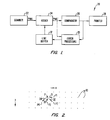
- Fig. 1 is a functional block diagram of a system for converting a multiple level digital or continuous tone original image into a bi-level image to illustrate the preferred embodiment of the invention.
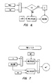
- Fig. 2 is a schematic view of pixel positions of an image to illustrate the error diffusion technique of this invention.
- Fig. 3 is a flow chart to illustrate the operation of the system of Fig. 1.
- Figs. 4-7 are system diagrams to illustrate the operation of the system of Fig. 1.
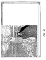
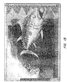
- Figs. 8-10 are bi-level images produced using conventional error diffusion techniques proposed by Floyd and Steinberg and Figs. 11-13 are the bi-level renditions of the same pictures using the techniques of this invention to illustrate the advantages of the invention.
- Fig. 14 is composed of 16 bi-level images of 16 different density levels rendered using the invention to illustrate its advantages.
- Fig. 1 is a functional block diagram of a system for converting a multiple level digital or continuous tone original image into bi-level image.
- System 20 includes a scanner 22 for scanning the original image to provide a signal Pval of a pixel or a block of pixels of the image scanned by the scanner indicating the density level of the pixel or block scanned.
- Adder 24 adds to the signal Pval an error correction term described below to provide a signal Pval' representing the corrected density level of the pixel or block scanned.
- Comparator 26 compares the signal Pval' to a threshold T having a predetermined value (diamond 54 of Fig. 3).
- T is one of a number of randomly variable threshold values evenly distributed around a predetermined value such as 128 in a range of density values from 0 to 255. If Pval' is greater than the threshold, the pixel or block is turned off and printer 28 is instructed to not print a colored dot at such pixel or block position (block 56 of Fig. 3). If Pval' is lower than the threshold, the pixel or block is turned on and printer 28 is instructed to print a colored dot at such pixel position (block 58 of Fig. 3).
- the bi-level output of comparator 26 and the corrected density level Pval' are supplied to error processing unit 30 to calculate the error terms of the converted pixel or block of pixels just described for distribution to at least two neighborhood pixels or blocks of pixels of such converted pixel or block.
- Error processing unit 30 performs the operations indicated in blocks 60-64 of Fig. 3. These error terms are then stored in line buffer 32.
- the correction term stored in buffer 32 corresponding to such pixel or block is then fetched from buffer 32 and added to the input signal to derive a corrected density level Pval'.
- blocks 66 and 52 the correction terms for neighboring pixels or blocks derived by error processing unit 30 are stored in the line buffer which are then provided to adder 24 when the signals representing the density levels of such neighboring pixels or blocks are processed by adder 24.
- Fig. 2 is a schematic diagram of dots printed by a printer in a rectangular grid to illustrate the invention.
- printer 28 (not shown in Fig. 2) is capable of printing a two-dimensional array of dots such as dots 40 shown in Fig. 2.
- the dots 40 shown are much smaller than their actual size; when all of the dots 40 are actually printed, the whole area of the image shown in Fig. 2 will be of a particular color from the colorant that is being printed.
- the printer prints one dot at a time so that the two-dimensional array shown in Fig. 2 is printed one row at a time, for example, from top to bottom in the y direction and the dots in each row are printed, for example, from left to right in the "x" direction. After the printer has finished printing one row of pixels, the printer would then move in the y direction to the next row to print the next row of dots in the "x" direction.
- system 20 of Fig. 1 processes the conversion of the density level at point P in Fig. 2, system 20 derives correction terms which are distributed to points P1, P2, P3 and P4, the same four points to which errors are diffused or distributed as proposed by Floyd and Steinberg.
- the error terms to be distributed to these four points are obtained by multiplying by certain weights the quantization error which results when comparator 26 converts the density level of the pixel P to a bi-level output.
- the density level is less than the threshold, and the pixel or block is turned on, then the density level itself is the error.
- the difference between the maximum value of the density level (255 in this case) and the actual density level at pixel P is the error and is derived in accordance with block 60.
- This error term may be derived in unit 30 by subtracting the output of comparator 26 and the corrected density level Pval', where the output of comparator 26 is a "1" or a "0" and the corrected density level Pval' is normalized as a fraction of the maximum value of the density level (255 in this case).
- Such difference is then multiplied by a weight characteristic of the direction of distribution.
- the weight is w 1 , or in general where the distribution is in the direction Dn, the weight applied is w n , where n ranges from "1" to "4.”
- the four error terms to be distributed to the four points P1, P2, P3, P4 are respectively: w 1 .”error”, w 2 .”error”, w 3 .”error” and w 4 .”error", where "error” is computed as described above by computing the difference between the output of comparator 26 and the normalized output of adder 24. Then these four error terms are stored in line buffer 32.
- scanner 22 provides the scanned density level at the next pixel P1 to adder 24, the error term w 1 .”error” is fetched from buffer 32 and is added to the density level scanned to provide the corrected density level for P1 at the output of adder 24 to be processed in the same manner as described above.
- the total correction at points P2, P3 will be updated by adding to each correction term stored in the line buffer for each of the two points, the additional correction term that is derived when the density level at point P1 is being converted to bi-level. This is repeated until the density level at point P3 or point P4 is scanned and processed, at which time the cumulative correction terms are then added by adder 24 to provide a corrected density level, which is then processed as before to provide a bi-level output and to carry on further error processing.
- the weights w 1 , w 2 , w 3 and w 4 in conventional error diffusion systems have fixed values.
- error diffusion schemes give rise to patterned artifacts or "worms.”
- This invention is based on the observation that these "worms" can be reduced or even eliminated in the light or dark areas of a picture by introducing a certain amount of periodicity to the location of the dots printed by the printer. This reduces the patterned artifacts or "worms,” particularly in the highlight portions or dark portions of a picture reproduced in digital halftone.
- this is achieved by detecting whether the scanned density level of a pixel or block of pixels is above a certain value such as "192" or below a certain value such as "63,” where the density level may range from “0" to "255.”
- the weights w 1 , w 2 , w 3 and w 4 are made to include a component which varies with the position of the pixel or block and which is periodic with respect to a wavelength which is a function of the density level or corrected density level of such pixel or block for the purpose of calculating error correction terms for neighboring pixels or blocks.
- the weights have periodic components with respect to wavelengths that are functions of the corrected density level.
- Block 62 of Fig. 3 is illustrated in more detail in Figs. 4-7.
- at least one of the four weights w 1 , w 2 , w 3 and w 4 is a sine function of the location of the pixel or block to be converted, where the sine function is periodic with respect to a wavelength which is a function of the corrected density level.
- the derivation of the four weights w 1 , w 2 , w 3 and w 4 may be accomplished by means of the systems in Figs. 4 and 5.
- I is the distance of pixel P from the y axis.
- the wavelength ⁇ of dots to be printed can be fetched from a lookup table as a function of the corrected density level Pval'.
- the dot pattern printed by the printer at such location therefore repeats for every half of the wavelength ⁇ .
- the weight w 4 is therefore a sine function of the position of the pixel or block and is periodic with respect to a wavelength ⁇ which is a function of the corrected density level of the pixel or block.
- the expression for weight w 4 is designed to ensure that the weight does not go negative.
- weights with periodicity are introduced only when the corrected density level is above a certain value such as "192" for a highlight area or below a certain value such as "63" for a dark area of an image.
- introducing periodicity in the correction term may be desirable only when the corrected density level of pixels or blocks of pixels are within certain range of values. When the corrected density levels are outside such ranges, it may be desirable for the weights to remain constant, as in the conventional error diffusion approach.
- the invention is best illustrated by reference to an example below, where periodicity is introduced in the correction terms when the corrected density level is in the range of "192" to "255,” that is, in the highlight portion of the image. It will be understood, however, that the invention is readily applicable to a dark area, where the corrected density level is below a certain value, such as "63;" all such variations are within the scope of the invention.
- each of the four weights used in computing the four correction terms will have a component which is periodic with respect to the wavelength of dot density as discussed above.
- the four weights also have constant components that do not vary as a function of the position of the pixel or block of the wavelength, so that the weights employed are each a blend of a periodic component and a constant component.
- Figs. 6 and 7 together with Fig. 3 illustrate a system for computing the correction terms to implement the above equations.
- the corrected density level Pval' is provided to error processing unit 30 for calculating the weights w 1 ", w 2 ", w 3 " and w 4 ".
- error processing unit 30 performs the following operations. The number "192" is subtracted from the corrected density level Pval' and the result is checked. If the result is negative, the quantity Vblend is set to "0.” If the quantity is smaller than "0,” it is divided by "63” which then becomes the value of Vblend, which is the same as the quantity "temp” in equations 8-12 above.
- the invention has been described above by referenced to a scheme where correction terms are distributed to four neighborhood pixels or blocks, it will be understood that a different number of correction terms may be derived for distribution to a different number of neighborhood of pixels or blocks, such as deriving at least two correction terms for at least two neighborhood pixels or blocks.
- the at least two pixels or blocks to which the error correction terms are to be distributed are not collinear with the pixel or block from which the error correction terms are derived.
- the corrected density value Pval' is used for deriving the error correction term, it will be understood that the uncorrected density value may be used instead and is within the scope of the invention.
- Figs. 8-10 Halftone images achieved using the conventional Floyd and Steinberg system are illustrated in Figs. 8-10, whereas an error diffusion rendition of the same pictures using this invention are illustrated in Figs. 11-13.
- a comparison of the two sets of pictures will illustrate that, for the images produced using the error diffusion scheme of this invention, the highlight and dark portions of the images contain a much more orderly distribution of colored dots, where patterned artifacts or "worms" are not noticeable, in contrast to the highlight and dark areas in the images reproduced using the conventional error diffusion scheme.
- Fig. 14 is composed of 16 bi-level images of 16 different density levels rendered using the invention to illustrate its advantages.
Landscapes
- Engineering & Computer Science (AREA)
- Multimedia (AREA)
- Signal Processing (AREA)
- Facsimile Image Signal Circuits (AREA)
- Image Processing (AREA)
Claims (23)
- Appareil pour convertir une image originale à teintes continues ou numérique multiniveau selon une image biniveau, dans lequel des erreurs de quantification lors de la conversion de niveaux de densité de pixels ou de blocs de pixels de l'image sont distribuées sur des pixels voisins ou des blocs de pixels voisins, ledit appareil comprenant:un dispositif de balayage (22) pour balayer ladite image originale afin de détecter les niveaux de densité de pixels ou de blocs de pixels dans une plage prédéterminée de longueurs d'onde optiques;des moyens (24) pour additionner au niveau de densité de chacun d'une pluralité de pixels ou de blocs de pixels balayés un terme de correction d'erreur afin de produire un niveau de densité corrigé pour ledit pixel ou ledit bloc de pixels afin de convertir ledit pixel ou ledit bloc;des moyens (26) pour comparer le niveau de densité corrigé de chacun desdits pixels ou desdits blocs de pixels à un seuil prédéterminé et pour produire une sortie biniveau correspondant au pixel ou au bloc de pixels; etdes moyens (30) pour dériver, à partir du niveau de densité corrigé de chacun desdits pixels ou desdits blocs de pixels et à partir de la sortie biniveau des moyens de comparaison et de production (26), des termes de correction d'erreur de ce pixel ou de ce bloc de pixels pour une distribution sur au moins deux pixels ou blocs de pixels voisins de ce pixel ou de ce bloc de pixels, dans lequel, pour au moins un pixel ou un bloc de pixels converti dont un niveau de densité ou un niveau de densité corrigé est dans une plage prédéterminée, le terme de correction de ce pixel ou de ce bloc présente une composante qui varie en fonction de la position du pixel ou du bloc de pixels par rapport à une référence et qui est périodique par rapport à une longueur d'onde de point spatiale qui est une fonction du niveau de densité ou du niveau de densité corrigé dudit pixel ou dudit bloc.
- Appareil selon la revendication 1, dans lequel les pixels sont agencés selon un réseau bidimensionnel par rapport à une direction d'impression, où chacun desdits pixels ou desdits blocs de pixels et ses au moins deux pixels ou blocs de pixels voisins correspondants sont non colinéaires.
- Appareil selon la revendication 1, lesdits moyens de dérivation (30) incluant un filtre d'erreur qui, pour chacun desdits pixels ou desdits blocs de pixels dont des niveaux de densité ont été convertis et pour lesquels des termes de correction ont été dérivés, distribue sur des pixels ou des blocs de pixels voisins de ce pixel ou bloc des termes de correction donnés par des parties pondérées de la différence entre le niveau de densité corrigé de chacun desdits pixels ou desdits blocs de pixels et la sortie biniveau pour ce pixel ou bloc.
- Appareil selon la revendication 3, dans lequel lesdits termes de correction d'un pixel ou d'un bloc sont donnés par les produits de poids et de ladite différence pour ce pixel ou bloc et dans lequel, pour des pixels ou des blocs de pixels dont des niveaux de densité corrigés sont dans ladite plage, lesdits poids sont des fonctions des niveaux de densité corrigés de ces pixels ou blocs.
- Appareil selon la revendication 4, dans lequel ladite plage est définie par des valeurs supérieures ou égales à une première valeur et inférieures à une seconde valeur supérieure à la première valeur ou par des valeurs inférieures ou égales à une première valeur et supérieures à une seconde valeur inférieure à la première valeur.
- Appareil selon la revendication 5, dans lequel des valeurs des niveaux de densité et des niveaux de densité corrigés sont dans la plage de 0 à 255 et dans lequel ladite première valeur est d'environ 192 et ladite seconde valeur est d'environ 63.
- Appareil selon la revendication 5, dans lequel, pour chaque pixel ou chaque bloc de pixels dont un niveau de densité corrigé est dans ladite plage, lesdits poids pour ledit pixel ou ledit bloc de pixels incluent en outre des composantes qui sont sensiblement égales aux produits de ladite différence et de constantes.
- Appareil selon la revendication 7, dans lequel, pour chaque pixel ou chaque bloc de pixels dont un niveau de densité corrigé est dans ladite plage, au moins quatre termes de correction de ce pixel ou bloc sont distribués sur des pixels ou blocs de pixels voisins, où lesdits poids pour les quatre termes de correction incluent w1", w2", w3", w4" donnés par:oùPval' étant le niveau de densité corrigé dudit pixel ou bloc;wn' étant des constantes;où I est la distance dudit pixel ou bloc depuis un axe de référence suivant une direction d'impression et λ est la longueur d'onde qui est une fonction prédéterminée du niveau de densité ou du niveau de densité corrigé dudit pixel ou bloc.n = 1, 2, 3, 4;w4 = 0,5 [sin(π/2 - 2πx/λ) + 1];w1 = 1 - w4;w2 = w3 = 0;x = λ/2 - I.modλ;
- Appareil selon la revendication 8, dans lequel w1', w3' sont sensiblement égaux à 0,3 et w2', w4' sont sensiblement égaux à 0,2.
- Appareil selon la revendication 4, dans lequel lesdits poids incluent des expressions qui sont proportionnelles à une fonction sinus qui est périodique par rapport à ladite longueur d'onde.
- Appareil selon la revendication 4, dans lequel, pour des pixels ou des blocs de pixels dont des niveaux de densité corrigés sont à l'extérieur de ladite plage, lesdits poids sont sensiblement constants.
- Appareil selon la revendication 11, dans lequel, pour chaque pixel ou bloc de pixels dont un niveau de densité corrigé est à l'extérieur de ladite plage, au moins quatre termes de correction de ce pixel ou bloc sont distribués sur des pixels ou blocs de pixels voisins, où lesdits poids pour les quatre termes de correction incluent w1", w2", w3", w4", où w1", w3" sont sensiblement égaux à 0,3 et w2", w4" sont sensiblement égaux à 0,2.
- Procédé pour convertir une image originale à teintes continues ou numérique multiniveau selon une image biniveau, dans lequel des erreurs de quantification lors de la conversion de niveaux de densité de pixels ou de blocs de pixels de l'image sont distribuées sur des pixels voisins ou des blocs de pixels voisins, ledit procédé comprenant:le balayage de ladite image originale pour détecter les niveaux de densité de pixels ou de blocs de pixels dans une plage prédéterminée de longueurs d'onde optiques;l'addition au niveau de densité de chacun d'une pluralité de pixels ou de blocs de pixels balayés d'un terme de correction d'erreur afin de produire un niveau de densité corrigé pour ledit pixel ou ledit bloc de pixels afin de convertir ledit pixel ou ledit bloc;la comparaison du niveau de densité corrigé de chacun desdits pixels ou desdits blocs de pixels à un seuil prédéterminé et la production d'une sortie biniveau correspondant au pixel ou au bloc de pixels; etla dérivation, à partir du niveau de densité corrigé de chacun desdits pixels ou desdits blocs de pixels et de la sortie biniveau de l'étape de comparaison et de production, de termes de correction d'erreur de ce pixel ou de ce bloc de pixels pour une distribution sur au moins deux pixels ou blocs de pixels voisins de ce pixel ou de ce bloc de pixels, où, pour au moins un pixel ou un bloc de pixels converti dont un niveau de densité ou un niveau de densité corrigé est dans une plage prédéterminée, le terme de correction de ce pixel ou de ce bloc présente une composante qui varie en fonction de la position du pixel ou du bloc de pixels par rapport à une référence et qui est périodique par rapport à une longueur d'onde de point spatiale qui est une fonction du niveau de densité ou du niveau de densité corrigé dudit pixel ou dudit bloc.
- Procédé selon la revendication 13, pour chacun desdits pixels ou desdits blocs de pixels dont des niveaux de densité ont été convertis et pour lesquels des termes de correction ont été dérivés, ladite étape de dérivation inclut l'étape de distribution sur des pixels ou des blocs de pixels voisins de ce pixel ou bloc de termes de correction donnés par des parties pondérées de la différence entre le niveau de densité corrigé de chacun desdits pixels ou desdits blocs de pixels et la sortie biniveau pour ce pixel ou bloc.
- Procédé selon la revendication 14, dans lequel ladite étape de distribution inclut la multiplication de poids et de ladite différence pour ce pixel ou bloc afin d'obtenir des termes de correction de ce pixel ou bloc et dans lequel, pour des pixels ou des blocs de pixels dont des niveaux de densité corrigés sont dans ladite plage, lesdits poids sont des fonctions des niveaux de densité corrigés de ces pixels ou blocs.
- Procédé selon la revendication 15, dans lequel ladite plage est définie par des valeurs supérieures ou égales à une première valeur et inférieures à une seconde valeur supérieure à la première valeur ou par des valeurs inférieures ou égales à une première valeur et supérieures à une seconde valeur inférieure à la première valeur.
- Procédé selon la revendication 16, dans lequel des valeurs des niveaux de densité et des niveaux de densité corrigés sont dans la plage de 0 à 255 et dans lequel ladite première valeur est d'environ 192 et ladite seconde valeur est d'environ 63.
- Procédé selon la revendication 16, dans lequel, pour chaque pixel ou chaque bloc de pixels dont un niveau de densité corrigé est dans ladite plage, lesdits poids pour ledit pixel ou ledit bloc de pixels incluent en outre des composantes qui sont sensiblement égales aux produits de ladite différence et de constantes.
- Procédé selon la revendication 18, dans lequel, pour chaque pixel ou chaque bloc de pixels dont un niveau de densité corrigé est dans ladite plage, au moins quatre termes de correction de ce pixel ou bloc sont distribués sur des pixels ou blocs de pixels voisins, où lesdits poids pour les quatre termes de correction incluent w1", w2", w3", w4" donnés par:oùPval' étant le niveau de densité corrigé dudit pixel ou bloc;wn' étant des constantes;où I est la distance dudit pixel ou bloc depuis un axe de référence suivant une direction d'impression et λ est la longueur d'onde qui est une fonction prédéterminée du niveau de densité ou du niveau de densité corrigé dudit pixel ou bloc.n = 1, 2, 3, 4;w4 = 0,5 [sin(π/2 - 2πx/λ) + 1];w1 = 1 - w4;w2 = w3 = 0;x = λ/2 - I.modλ;
- Procédé selon la revendication 19, dans lequel w1', w3' sont sensiblement égaux à 0,3 et w2', w4' sont sensiblement égaux à 0,2.
- Procédé selon la revendication 16, dans lequel lesdits poids incluent des expressions qui sont proportionnelles à une fonction sinus qui est périodique par rapport à ladite longueur d'onde.
- Procédé selon la revendication 16, dans lequel, pour des pixels ou des blocs de pixels dont des niveaux de densité corrigés sont à l'extérieur de ladite plage, lesdits poids sont sensiblement constants.
- Procédé selon la revendication 22, dans lequel, pour chaque pixel ou bloc de pixels dont un niveau de densité corrigé est à l'extérieur de ladite plage, au moins quatre termes de correction de ce pixel ou bloc sont distribués sur des pixels ou blocs de pixels voisins, où lesdits poids pour les quatre termes de correction incluent w1, w2", w3", w4", où w1", w3" sont sensiblement égaux à 0,3 et w2", w4" sont sensiblement égaux à 0,2.
Applications Claiming Priority (3)
| Application Number | Priority Date | Filing Date | Title |
|---|---|---|---|
| US07/722,592 US5130823A (en) | 1991-06-27 | 1991-06-27 | Error diffusion system |
| PCT/US1992/003729 WO1993000656A1 (fr) | 1991-06-27 | 1992-05-05 | Systeme ameliore a diffusion d'erreur |
| US722592 | 2000-11-28 |
Publications (3)
| Publication Number | Publication Date |
|---|---|
| EP0591274A4 EP0591274A4 (fr) | 1994-03-21 |
| EP0591274A1 EP0591274A1 (fr) | 1994-04-13 |
| EP0591274B1 true EP0591274B1 (fr) | 1999-07-14 |
Family
ID=24902513
Family Applications (1)
| Application Number | Title | Priority Date | Filing Date |
|---|---|---|---|
| EP92912198A Expired - Lifetime EP0591274B1 (fr) | 1991-06-27 | 1992-05-05 | Systeme ameliore a diffusion d'erreur |
Country Status (7)
| Country | Link |
|---|---|
| US (1) | US5130823A (fr) |
| EP (1) | EP0591274B1 (fr) |
| JP (1) | JP3571716B2 (fr) |
| AU (1) | AU1993292A (fr) |
| CA (1) | CA2112469C (fr) |
| DE (1) | DE69229599D1 (fr) |
| WO (1) | WO1993000656A1 (fr) |
Families Citing this family (26)
| Publication number | Priority date | Publication date | Assignee | Title |
|---|---|---|---|---|
| JP2500834B2 (ja) * | 1991-09-05 | 1996-05-29 | ゼロックス コーポレイション | 画素値の量子化方法及び装置 |
| JP3030981B2 (ja) * | 1991-09-26 | 2000-04-10 | 富士ゼロックス株式会社 | 中間調画像再現方法及びその装置 |
| EP0571010B1 (fr) | 1992-05-22 | 1997-03-12 | Agfa-Gevaert N.V. | Procédé perfectionné pour l'obtention de demi-teintes à modulation de fréquence |
| US5337160A (en) * | 1992-07-01 | 1994-08-09 | Hewlett-Packard | Error diffusion processor and method for converting a grey scale pixel image to a binary value pixel image |
| US5325211A (en) * | 1993-01-04 | 1994-06-28 | Xerox Corporation | Error diffusion with output and input based feedback |
| US5521989A (en) * | 1993-08-05 | 1996-05-28 | Xerox Corporation | Balanced error diffusion system |
| US5515456A (en) * | 1993-10-26 | 1996-05-07 | Visual Edge Technology, Inc. | Process for providing digital halftone image with random error diffusion, color correction and enlargement |
| US5588094A (en) * | 1994-01-03 | 1996-12-24 | Tektronix, Inc. | Post-processing bit-map decimation compensation method for printing high quality images |
| US5563985A (en) * | 1994-01-05 | 1996-10-08 | Xerox Corporation | Image processing method to reduce marking material coverage in printing processes |
| JP3603906B2 (ja) * | 1994-04-15 | 2004-12-22 | 富士写真フイルム株式会社 | 画像信号2値化処理装置および方法 |
| US5467201A (en) * | 1994-05-31 | 1995-11-14 | Xerox Corporation | Iterative error diffusion system |
| US5534945A (en) * | 1994-12-16 | 1996-07-09 | International Business Machines Corporation | System and method for providing black diffusion in video image processing |
| US5587811A (en) * | 1995-04-28 | 1996-12-24 | Dataproducts Corporation | Halftone screen using spot function to rank pixels following one or more design rules |
| US5821915A (en) * | 1995-10-11 | 1998-10-13 | Hewlett-Packard Company | Method and apparatus for removing artifacts from scanned halftone images |
| US5737453A (en) * | 1996-05-17 | 1998-04-07 | Canon Information Systems, Inc. | Enhanced error-diffusion method for color or black-and-white reproduction |
| US5835687A (en) * | 1996-10-21 | 1998-11-10 | Vidar Systems Corporation | Methods and apparatus for providing digital halftone images with random error diffusion dithering |
| JPH10271331A (ja) * | 1997-03-26 | 1998-10-09 | Oki Data:Kk | 画像処理方法及びその装置 |
| US6081340A (en) * | 1997-03-31 | 2000-06-27 | Xerox Corporation | Image processing method to reduce marking material coverage with non-linear specifications |
| US6137519A (en) * | 1997-06-12 | 2000-10-24 | 3M Innovative Properties Company | System and method for reducing striations in electrostatic printing |
| US6185005B1 (en) | 1998-04-30 | 2001-02-06 | Hitachi Koki Imaging Solutions, Inc. | Half tone image enhancement for printers |
| US6671835B1 (en) | 2000-05-15 | 2003-12-30 | International Business Machines Corporation | Error detection in digital scanning device having parallel data streams |
| US7551323B2 (en) * | 2003-04-16 | 2009-06-23 | Lexmark International, Inc. | Systems and methods for error diffusion |
| JP2005012726A (ja) * | 2003-06-23 | 2005-01-13 | Konica Minolta Business Technologies Inc | 画像処理装置および画像処理方法 |
| US6977663B2 (en) * | 2004-03-29 | 2005-12-20 | Sharp Laboratories Of America, Inc. | Color error diffusion with color bleed control |
| US7639887B2 (en) | 2004-12-14 | 2009-12-29 | Intel Corporation | Error diffusion-based image processing |
| CN110455219A (zh) * | 2019-07-05 | 2019-11-15 | 苏州江奥光电科技有限公司 | 一种基于误差扩散抖动算法的三维成像方法 |
Family Cites Families (13)
| Publication number | Priority date | Publication date | Assignee | Title |
|---|---|---|---|---|
| US4205341A (en) * | 1978-01-24 | 1980-05-27 | Nippon Telegraph And Telephone Public Corporation | Picture signal coding apparatus |
| US4196454A (en) * | 1978-12-04 | 1980-04-01 | Xerox Corporation | Tone error control for relatively large image areas |
| EP0031247B1 (fr) * | 1979-12-20 | 1984-03-14 | Cambridge Consultants Limited | Dispositif et procédé pour la fabrication d'une image demi-ton se composant de points dispersés à partir d'une image sans graduation |
| DE3176774D1 (en) * | 1980-12-10 | 1988-07-07 | Fuji Xerox Co Ltd | Elongate thin-film reader |
| US4449150A (en) * | 1981-01-19 | 1984-05-15 | Ricoh Company, Ltd. | Method of processing medium tone picture |
| US4466021A (en) * | 1982-09-21 | 1984-08-14 | Terminal Data Corporation | Electronic camera |
| US4654721A (en) * | 1985-04-12 | 1987-03-31 | International Business Machines Corporation | System for reproducing multi-level digital images on a bi-level printer of fixed dot size |
| US4890167A (en) * | 1986-10-17 | 1989-12-26 | Matsushita Electric Industrial Co., Ltd. | Apparatus for processing image signal |
| US5008950A (en) * | 1987-01-22 | 1991-04-16 | Canon Kabushiki Kaisha | Image processing method and apparatus for error-dispersion digitization without moire or spurious stripe formation |
| US4975786A (en) * | 1987-12-28 | 1990-12-04 | Canon Kabushiki Kaisha | Image processing method and apparatus with error diffusion capability |
| JP2683014B2 (ja) * | 1988-03-08 | 1997-11-26 | キヤノン株式会社 | 画像処理方法及び装置 |
| US4962542A (en) * | 1988-08-29 | 1990-10-09 | Eastman Kodak Company | Method for reducing artifacts in error diffused images |
| US4891714A (en) * | 1989-04-24 | 1990-01-02 | Eastman Kodak Company | Apparatus for non-linear error diffusion thresholding of multilevel video images |
-
1991
- 1991-06-27 US US07/722,592 patent/US5130823A/en not_active Expired - Lifetime
-
1992
- 1992-05-05 WO PCT/US1992/003729 patent/WO1993000656A1/fr active IP Right Grant
- 1992-05-05 JP JP50145093A patent/JP3571716B2/ja not_active Expired - Fee Related
- 1992-05-05 CA CA002112469A patent/CA2112469C/fr not_active Expired - Fee Related
- 1992-05-05 EP EP92912198A patent/EP0591274B1/fr not_active Expired - Lifetime
- 1992-05-05 AU AU19932/92A patent/AU1993292A/en not_active Abandoned
- 1992-05-05 DE DE69229599T patent/DE69229599D1/de not_active Expired - Lifetime
Also Published As
| Publication number | Publication date |
|---|---|
| CA2112469A1 (fr) | 1993-01-07 |
| CA2112469C (fr) | 2001-02-27 |
| DE69229599D1 (de) | 1999-08-19 |
| JPH07501428A (ja) | 1995-02-09 |
| EP0591274A1 (fr) | 1994-04-13 |
| AU1993292A (en) | 1993-01-25 |
| WO1993000656A1 (fr) | 1993-01-07 |
| JP3571716B2 (ja) | 2004-09-29 |
| EP0591274A4 (fr) | 1994-03-21 |
| US5130823A (en) | 1992-07-14 |
Similar Documents
| Publication | Publication Date | Title |
|---|---|---|
| EP0591274B1 (fr) | Systeme ameliore a diffusion d'erreur | |
| EP0702482B1 (fr) | Obtention de demi-teintes par diffusion d'erreurs avec réponse homogène dans des régions d'images de forte/faible intensité | |
| EP0749231B1 (fr) | Procédé et appareil pour rendre en demi-teinte une image d'échelle de gris à l'aide d'un masque de bruit bleu | |
| US5325448A (en) | Image treatment method and apparatus with error dispersion and controllable quantization | |
| US5353127A (en) | Method for quantization gray level pixel data with extended distribution set | |
| EP0545734B1 (fr) | Obtention de demi-teintes à rétroaction d'erreurs et à amélioration dépendante de l'image | |
| EP0639023B1 (fr) | Procédé de fabrication des images de demi-teintes à modulation de fréquence | |
| EP1505821B1 (fr) | Appareil et procédé de traitement d'images et appareil de formation d'images | |
| US5521989A (en) | Balanced error diffusion system | |
| EP0531170A2 (fr) | Méthode de quantification de données de pixel à tonalité de gris avec mise en oeuvre de diffusion d'erreur sous compensée | |
| JPH06233121A (ja) | 画像処理システム | |
| JP3973734B2 (ja) | 電子イメージ処理システム及び処理方法 | |
| EP0710006B1 (fr) | Appareil de formation d'images capable de produire des images en pseudo demi-teintes par l'utilisation de modèles de tremblement | |
| US5289294A (en) | Image processing apparatus | |
| US5493416A (en) | Method combining error diffusion and traditional halftoning with arbitrary screen orientation | |
| US5157741A (en) | Image processing method and apparatus for out-putting dot-processed data with suppression of false contours and other noise | |
| EP0817466B1 (fr) | Diffusion des erreurs avec amélioration des bords | |
| CA2313774C (fr) | Procede et appareil servant a produire des matrices de seuils en minimisant la variance et en calculant les angles des pixels | |
| JPH0622123A (ja) | ディジタル画像用ハーフトーンマスク及びその作成方法 | |
| US6026199A (en) | Method and apparatus for halftoning grey value signals | |
| EP0382580B1 (fr) | Dispositif pour le traitement d'images | |
| JPH01115271A (ja) | 画像処理装置 | |
| JP2733314B2 (ja) | 画像処理装置 | |
| JPH01157166A (ja) | 画像処理装置 | |
| JPH06164935A (ja) | 画像処理方法 |
Legal Events
| Date | Code | Title | Description |
|---|---|---|---|
| PUAI | Public reference made under article 153(3) epc to a published international application that has entered the european phase |
Free format text: ORIGINAL CODE: 0009012 |
|
| 17P | Request for examination filed |
Effective date: 19940121 |
|
| AK | Designated contracting states |
Kind code of ref document: A1 Designated state(s): DE FR GB IT |
|
| RHK1 | Main classification (correction) |
Ipc: H04N 1/40 |
|
| 17Q | First examination report despatched |
Effective date: 19960410 |
|
| RAP1 | Party data changed (applicant data changed or rights of an application transferred) |
Owner name: MINNESOTA MINING AND MANUFACTURING COMPANY |
|
| GRAG | Despatch of communication of intention to grant |
Free format text: ORIGINAL CODE: EPIDOS AGRA |
|
| GRAG | Despatch of communication of intention to grant |
Free format text: ORIGINAL CODE: EPIDOS AGRA |
|
| GRAH | Despatch of communication of intention to grant a patent |
Free format text: ORIGINAL CODE: EPIDOS IGRA |
|
| GRAH | Despatch of communication of intention to grant a patent |
Free format text: ORIGINAL CODE: EPIDOS IGRA |
|
| GRAA | (expected) grant |
Free format text: ORIGINAL CODE: 0009210 |
|
| AK | Designated contracting states |
Kind code of ref document: B1 Designated state(s): DE FR GB IT |
|
| PG25 | Lapsed in a contracting state [announced via postgrant information from national office to epo] |
Ref country code: IT Free format text: LAPSE BECAUSE OF FAILURE TO SUBMIT A TRANSLATION OF THE DESCRIPTION OR TO PAY THE FEE WITHIN THE PRE;WARNING: LAPSES OF ITALIAN PATENTS WITH EFFECTIVE DATE BEFORE 2007 MAY HAVE OCCURRED AT ANY TIME BEFORE 2007. THE CORRECT EFFECTIVE DATE MAY BE DIFFERENT FROM THE ONE RECORDED.SCRIBED TIME-LIMIT Effective date: 19990714 Ref country code: FR Free format text: LAPSE BECAUSE OF FAILURE TO SUBMIT A TRANSLATION OF THE DESCRIPTION OR TO PAY THE FEE WITHIN THE PRESCRIBED TIME-LIMIT Effective date: 19990714 |
|
| REF | Corresponds to: |
Ref document number: 69229599 Country of ref document: DE Date of ref document: 19990819 |
|
| PG25 | Lapsed in a contracting state [announced via postgrant information from national office to epo] |
Ref country code: DE Free format text: LAPSE BECAUSE OF FAILURE TO SUBMIT A TRANSLATION OF THE DESCRIPTION OR TO PAY THE FEE WITHIN THE PRESCRIBED TIME-LIMIT Effective date: 19991015 |
|
| EN | Fr: translation not filed | ||
| PLBE | No opposition filed within time limit |
Free format text: ORIGINAL CODE: 0009261 |
|
| STAA | Information on the status of an ep patent application or granted ep patent |
Free format text: STATUS: NO OPPOSITION FILED WITHIN TIME LIMIT |
|
| 26N | No opposition filed | ||
| REG | Reference to a national code |
Ref country code: GB Ref legal event code: IF02 |
|
| PGFP | Annual fee paid to national office [announced via postgrant information from national office to epo] |
Ref country code: GB Payment date: 20030430 Year of fee payment: 12 |
|
| PG25 | Lapsed in a contracting state [announced via postgrant information from national office to epo] |
Ref country code: GB Free format text: LAPSE BECAUSE OF NON-PAYMENT OF DUE FEES Effective date: 20040505 |
|
| GBPC | Gb: european patent ceased through non-payment of renewal fee |
Effective date: 20040505 |