EP0639023B1 - Procédé de fabrication des images de demi-teintes à modulation de fréquence - Google Patents
Procédé de fabrication des images de demi-teintes à modulation de fréquence Download PDFInfo
- Publication number
- EP0639023B1 EP0639023B1 EP94201857A EP94201857A EP0639023B1 EP 0639023 B1 EP0639023 B1 EP 0639023B1 EP 94201857 A EP94201857 A EP 94201857A EP 94201857 A EP94201857 A EP 94201857A EP 0639023 B1 EP0639023 B1 EP 0639023B1
- Authority
- EP
- European Patent Office
- Prior art keywords
- threshold value
- halftone
- tone
- value
- gradation
- Prior art date
- Legal status (The legal status is an assumption and is not a legal conclusion. Google has not performed a legal analysis and makes no representation as to the accuracy of the status listed.)
- Expired - Lifetime
Links
Images


Classifications
-
- H—ELECTRICITY
- H04—ELECTRIC COMMUNICATION TECHNIQUE
- H04N—PICTORIAL COMMUNICATION, e.g. TELEVISION
- H04N1/00—Scanning, transmission or reproduction of documents or the like, e.g. facsimile transmission; Details thereof
- H04N1/40—Picture signal circuits
- H04N1/407—Control or modification of tonal gradation or of extreme levels, e.g. background level
-
- H—ELECTRICITY
- H04—ELECTRIC COMMUNICATION TECHNIQUE
- H04N—PICTORIAL COMMUNICATION, e.g. TELEVISION
- H04N1/00—Scanning, transmission or reproduction of documents or the like, e.g. facsimile transmission; Details thereof
- H04N1/40—Picture signal circuits
- H04N1/405—Halftoning, i.e. converting the picture signal of a continuous-tone original into a corresponding signal showing only two levels
- H04N1/4051—Halftoning, i.e. converting the picture signal of a continuous-tone original into a corresponding signal showing only two levels producing a dispersed dots halftone pattern, the dots having substantially the same size
Definitions
- the present invention relates to the halftoning of continuous tone images for use in high quality reproduction of such images.
- a typical digital film recorder consists of a scanning laser beam exposing a photosensitive material at high resolution.
- the "grid” that defines the resolution at which the laser beam can be switched on or off usually has an element size in the range of 1/1800 of an inch.
- the photosensitive material can be a photographic film, from which a printing plate is later prepared by means of photomechanical techniques.
- the smallest addressable unit on a recorder is often called a "micro dot", “recorder element", or "rel”.
- a dot-size modulated halftone dot is made up of a clustered set of recorder elements, while frequency modulated halftone dots constitute a dispersed set of individual recording elements.
- Amplitude modulation screening has as its major advantages that it has excellent photomechanical reproduction characteristics, and that, for screens with rulings up to 200 dots / inch, it prints predictably on offset presses.
- An important disadvantage of amplitude modulation screening is the fact that unwanted patterns can occur within the halftoned image. Depending on their origin, these patterns are called subject moiré, color moiré and internal moiré. Subject moiré results from the geometric interaction between periodic components in the original subject matter and the halftone screen itself. Methods addressing subject moiré are disclosed in e.g. US-A-5,130,821, EP-A-369,302 and EP-A-488,324. These methods do not, however, completely solve the problem.
- Internal moiré refers to patterns resulting from the geometric interaction between the halftones and the addressable grid on which they are rendered.
- Methods to reduce internal moiré are usually based on the introduction of a random element that breaks up or "diffuses" the phase error that periodically builds up as a consequence of the frequency and angle relation between the halftone screen and the addressable grid on which it is rendered. Examples of such techniques are disclosed in US-A-4,456,924, US-A-4,499,489, US-A-4,700,235, US-A-4,918,622, US-A-5,150,428 and WO-A-90/04898.
- dot frequency modulation screening techniques have been disclosed and they can be divided into the following subclasses: (1) Point-to-point thresholding based techniques; (2) Error Diffusion techniques (and their variations); and, (3) Special techniques, such as that disclosed in DE-A-29,31,092, and further developed in US-A-4,485,397.
- Bayer dither matrix Bayer B.E., "An Optimum Method for Two-Level Rendition of Continuous-Tone Pictures", Proc. IEEE International Conference on Communications, Conference Record, pp. (26-11), (26-15), 1973.
- This Bayer dither matrix has a size that is a power of two, and contains threshold values that are arranged in such a fashion that, when thresholded against increasing levels of density, every halftone dot is "as far away as possible” from the halftone dots that are used to render the lower density levels.
- Another point-to-point thresholding technique uses a "Blue Noise Mask” instead of a Bayer dither matrix. It is described in US-A-5,111,310.
- the Blue Noise Mask is the result of an optimization (filtering) of a non-deterministic randomized mask performed iteratively (for the subsequent threshold "layers") between the halftone dot patterns produced by the mask and their Fourier transform.
- the halftone dot patterns produced by the Bayer dither matrix contain strong periodic components, visible as "texture” that can potentially create moiré problems similar to the dot-size modulation algorithms. Because the energy of the periodic dither components is "spread" over the different harmonics, and because most of these harmonics have a relatively high frequency compared to the fundamental frequency of dot-size modulation, the moiré which occurs is less disturbing.
- the "Blue Noise Mask” threshold matrix produces distributions of halftone dots which are aperiodic. This method is therefore free of the moiré problems which occur with the dot-size modulation methods or with the Bayer dither matrix.
- the aperiodic character of the halftone dot distributions of the Blue Noise Mask technique translates in the frequency domain into a "continuous" power spectrum. This suggests that at least some energy is also present in the very low frequency bands of the spectrum. This energy at low (visible) spatial frequencies is one of the reasons why tints rendered with the Blue Noise Mask technique may appear grainy.
- the relation between "graininess” introduced by frequency modulation halftoning techniques and the shape of the frequency spectrum is extensively discussed by Ulichney, Robert, "Digital Halftoning", MIT Press Cambridge Massachusetts, 1987, ISBN 0-262-21009-6.
- tone gain arises from the fact that halftone dots can change their size in the various steps of the reproduction process.
- the first place where this takes place is during the recording of the halftone dots on film.
- An "ideal recorder” would be capable of imaging "square" recorder elements with a size equal to one recording period on its addressable grid.
- a rigorous analysis is more complicated than it first appears, it is quite easy to accept the fact that in most practical systems, the optics of the recorder are not able to focus the scanning laser beam well enough to achieve this ideal. Instead, a recorder element is imaged as a more or less rounded square spot with an area that exceeds the area of an ideal recorder element. This results in a gain in size of the black halftone dots on the film. On positive films, this results in a tone reproduction that makes the image generally darker. On negative films, on the other hand, it makes the printed image lighter.
- a second step in which changes in dot size can occur is the plate-making process.
- In the positive plate-making process internal light diffusion causes a smaller area on the plate to remain hydrophobic than the area of the corresponding black dot on the film. The resulting image is accordingly lighter than that corresponding to the film.
- In the negative plate-making process on the other hand, light diffusion causes a slightly larger area on the plate to become hydrophobic than the white (negative) dot on the film. Hence the dot that is printed is enlarged as a consequence of this effect, darkening the image.
- a third place where dots change size is on the printing press itself.
- Two effects take place in this case.
- a second effect is called “optical dot gain”, and is related to the optical dispersion which takes place in the paper at the boundaries of the halftone dots.
- FIG. 2 shows that a certain fraction of the light that has been spectrally filtered by the halftone dot near its boundary is diffused to the outside of the halftone dot, making the halftone dot effectively appear larger.
- Physical and optical dot gain each cause an apparent increase in the size of dots, and therefore cause tones to be rendered darker.
- FIG. 1A and FIG. 1B compares clustered dots and a distribution of dispersed dots having the same total area.
- the total perimeter of the dispersed dots in FIG. 1A however is four times larger than that of the clustered dots in FIG. 1B, and the total amount of gain is therefore expected to be four times as large.
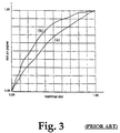
- FIG. 3 shows the result of the above discussions in practical situations.
- the x-axis shows the nominal dot value on a scale from 0.0 to 1.0. This is the digital value dot area as it is offered to the halftoning process.
- On the y-axis is shown the "dot area on paper" as it is obtained from the spatially-integrated density value using the Murray Davis equation.
- the Murray Davis equation is a mathematical translation of the assumption that a dot area can be associated with a tint that is proportional to the amount of its spatially integrated absorption (See Yule, J. A. "Principles of Color Reproduction", John Wiley and Sons, 1967 ).
- the curve (a) shows the gradation that is obtained with a 150 line per inch (lpi) conventional screen
- the curve (b) is the result of measurement of a dispersed halftone with dots having a size of 21 microns.
- Both (a) and (b) show the global gradation of a negative plate making process (i.e., recorder gain, plate gain, physical and optical press gain).
- the total gain of the dispersed dot dither is significantly higher than the total gain of the clustered dot dither.
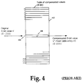
- Loss of resolution in the compensated values V' can be particularly severe if the lookup table of FIG. 4 must compensate for the steep gradation produced by a dispersed dot dither algorithm, in which case it is possible that the number of shades is reduced sufficiently to show visible tone quantization in the final image reproduction. It can be calculated that, if the gradation of curve (a) in FIG. 3 is compensated using an 8-bit table lookup procedure, the effective number of visible shades is reduced from the initial 256 to approximately 180.
- a periodic screen function for gradation correction is known in the art.
- S is a screening or thresholding function which is periodic with regard to the position coordinate x, thereby yielding a set of values S(x) for given values of x.
- V(x) represents the pixel values as a function of the position coordinate x.
- Halftoning is achieved by comparing at every position x the pixel value V(x) with the screen function value S(x).
- the integrated halftone dot value over the distance from 0 to X is equal to:
- the average halftone dot value A over the distance from 0 to X equals: Assuming now that:
- a non-periodic screen function and in particular a stochastic screen function, produces such an increase in dot size that it is all the more necessary to be able to perform gradation compensation without loss of tone scale.
- FREQUENCY-MODULATION HALFTONING shall mean any halftoning technique except bi-level, exclusively dot-size modulated, halftoning based upon a periodic screen function. Specifically included but without limitation are:
- FREQUENCY-MODULATION HALFTONE SCREEN shall mean a screen generated by the process of FREQUENCY-MODULATION HALFTONING.
- NON-HALFTONE VALUE(S) shall mean one or more of the following value(s):
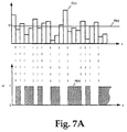
- a stochastic screen function S(x) produces a pseudo-random sequence of threshold values as shown in FIG. 7A.
- the average integrated halftone dot value is expressed by:
- the expression (7) is difficult to evaluate.
- the screen function S is replaced by another screen function S' which produces exactly the same threshold values as the original statistical screen function S but in a different sequence. More precisely, the sequence of the threshold values of the function S' is such that the threshold values S' (x) are ordered according to their values, from smallest to largest.
- FIG. 7B shows a one-dimensional representation of the altered function S' (x).
- the gradation of a halftone can be controlled by altering the screen function as opposed to altering the pixel values. If the screen function values are quantized after the transformation, the gradation control does not result in a loss of the number of reproducible shades.
- FIG. 8 shows a first circuit to perform the halftoning method for a non-periodic screen function in combination with a binary recording device.
- Block 802 is a memory block containing the contone pixel values of an image. Typically these are 8-bit values, organized as N lines with M columns. The contents of block 802 can for example be the result of scanning a photographic original image.
- Block 804 is a memory block with the same layout as block 802, in which the halftoned pixel values are to be stored after processing. In the case of a binary recording device, every halftoned pixel has a word length of 1 bit.
- Block 806 is a binary recording device, capable of recording the information on a substrate 808.
- Block 820 is a unit that produces uncorrected, uncompensated 16-bit threshold values representing the stochastic screen function.
- Block 822 is a lookup table which converts uncompensated 16-bit screen function values S 16 to compensated 8-bit screen function values S' 8 .
- Block 830 is a comparator and block 840 is an address generator.
- the address generator 840 sequentially generates the coordinate positions (i,j) corresponding to the indices i and j of all elements in block 802 and 804. At every coordinate position, a 16-bit screen function value S 16 (i,j) is produced by block 820, which is transformed into a corrected 8-bit threshold value S 8 (i,j) by the lookup table 822. This threshold value is compared with the pixel value V(i,j) in the comparator 830, and depending on the outcome of this comparison, a halftone dot value H(i,j), equal to 0 or to 1, is written at the coordinate position (i,j) of block 804. It will now be explained how the contents of lookup table 822 can be calculated.
- the gradation compensation function G(x) at that point is usually available in an "explicit" form, i.e., in the form of number pairs (x,G(x)).
- the lookup table 822 can contain data which alters the tone gradation of the input pixel values in any manner desired, subject only to the requirement that the function G(x) be monotonic in nature. Accordingly, in addition to or instead of the above calculation, any monotonic function can be reduced to explicit form and stored in the table, including one aimed at altering the tone gradation for aesthetic purposes.
- FIG. 9 A second circuit for gradation compensation using a non-periodic screen function is shown in FIG. 9.
- the circuit is based upon that previously described, except for the fact that it contains more than one screen function generator 820, each having its own correction lookup table 822. It should be noted that the contents of the LUT's 822 are in general different from each other, and apply to different regions of the contone image in memory 802.
- Selector switch 910 is coupled to address generator 840, and selects which one of the compensated 8-bit values is selected for comparison with the contone value V(i,j) at the comparator 830. This mechanism effectively allows screening of different parts of the contone image in block 802 with different screen functions.
- One part of the image can for example be screened with a dot-size modulation technique, while another part can be screened with a FREQUENCY-MODULATION HALFTONING technique.
- FIG. 10 shows an example of a circuit which can be used for implementation of error diffusion gradation compensation in combination with a binary recording device.
- the error diffusion algorithm in this drawing is one in which the halftoning error is entirely propagated to only one pixel.
- Block 1002 is a lookup table which transforms uncorrected 8-bit pixel values into corrected 16-bit values. The error of the previously halftoned pixel is added to the corrected halftone pixel with 16-bit precision in arithmetic unit 1006. At the next clock cycle, this 16-bit value is shifted through the delay register 1010. Comparator 1020 compares this value with the threshold value generated by block 1030. Depending on the outcome of this comparison, a halftone value of either 0 or 65536 is produced at the output of the comparator.
- the most significant bit of this number (which is either a 0 or a 1) is obtained as the output of shift register 1044, and used to turn the modulator of the laser recording device 806 either "on” or "off".
- a new error is then calculated in arithmetic unit 1040 from the difference between the halftoned value at the output of the comparator 1020 and the value at its input.
Claims (11)
- Procédé de production de valeurs de demi-teinte pour une image de tramage à modulation de fréquence à partir de pixels co-tonals d'une image à modelé continu, comprenant les étapes suivantes consistant à- produire une valeur de seuil T selon une fonction de grille non périodique S;- modifier ladite valeur de seuil T pour produire une valeur de seuil modifiée T' correspondante pour une compensation de la gradation; et- utiliser ladite valeur de seuil modifiée T' pour produire une valeur de demi-teinte à partir d'une valeur de pixel d'un pixel co-tonal;caractérisé en ce que ladite valeur de seuil T est produite à une résolution co-tonale supérieure à la résolution co-tonale de ladite valeur de pixel.
- Procédé selon la revendication 1, comprenant en outre les étapes consistant à:- produire une autre fonction de grille non périodique S2;- modifier ladite autre fonction de grille non périodique S2 pour produire une autre fonction de grille non périodique S2' correspondante; et- utiliser ladite autre fonction de grille non périodique S2' correspondante et des valeurs de pixels autres que ladite valeur de pixel pour produire au moins une valeur de demi-teinte pour ladite image de trame.
- Procédé selon la revendication 1 ou 2, dans lequel:la résolution tonale de ladite valeur de seuil modifiée T' est plus grossière queladite résolution tonale de ladite valeur de seuil T.
- Procédé selon l'une quelconque des revendications 1 à 3, comprenant les étapes consistant à:- définir une fonction de gradation tonale G voulue pour compenser la gradation des valeurs de pixels à restituer;- utiliser ladite fonction de gradation tonale G pour obtenir une fonction de gradation inverse G-1;- utiliser ladite fonction de gradation inverse G-1 pour modifier ladite valeur de seuil T afin de produire ladite valeur de seuil modifiée T'.
- Procédé selon l'une quelconque des revendications 1 à 4, dans lequel ladite valeur de seuil T ou ladite valeur de seuil modifiée T' compense les effets de gain de presse.
- Procédé selon l'une quelconque des revendications 1 à 5, dans lequel ladite valeur de seuil T ou ladite valeur de seuil modifiée T' compense les effets de gain d'enregistreur.
- Procédé selon l'une quelconque des revendications 1 à 6, dans lequel ladite valeur de seuil T ou ladite valeur de seuil modifiée T' compense les caractéristiques tonales dans un but esthétique.
- Procédé selon l'une quelconque des revendications 1 à 7, dans lequel ladite valeur de seuil T est modifiée à ladite résolution tonale de ladite valeur de seuil T.
- Procédé selon l'une quelconque des revendications 1 à 8, dans lequel lesdites valeurs de demi-teinte sont à deux niveaux.
- Procédé selon l'une quelconque des revendications 1 à 8, dans lequel lesdites valeurs de demi-teinte sont à plusieurs niveaux.
- Image tramée produite par le procédé selon l'une quelconque des revendications 1 à 10.
Applications Claiming Priority (2)
| Application Number | Priority Date | Filing Date | Title |
|---|---|---|---|
| US10633393A | 1993-08-13 | 1993-08-13 | |
| US106333 | 1993-08-13 |
Publications (2)
| Publication Number | Publication Date |
|---|---|
| EP0639023A1 EP0639023A1 (fr) | 1995-02-15 |
| EP0639023B1 true EP0639023B1 (fr) | 1997-06-04 |
Family
ID=22310857
Family Applications (1)
| Application Number | Title | Priority Date | Filing Date |
|---|---|---|---|
| EP94201857A Expired - Lifetime EP0639023B1 (fr) | 1993-08-13 | 1994-06-28 | Procédé de fabrication des images de demi-teintes à modulation de fréquence |
Country Status (4)
| Country | Link |
|---|---|
| US (1) | US5818604A (fr) |
| EP (1) | EP0639023B1 (fr) |
| JP (1) | JP3380337B2 (fr) |
| DE (1) | DE69403581T2 (fr) |
Families Citing this family (36)
| Publication number | Priority date | Publication date | Assignee | Title |
|---|---|---|---|---|
| EP0691577A1 (fr) * | 1994-07-06 | 1996-01-10 | Agfa-Gevaert N.V. | Procédé de fabrication d'une plaque d'impression lithographique |
| FR2722584B1 (fr) * | 1994-07-13 | 1996-10-31 | Nouel Jean Marie | Utilisation du tramage a modulation de frequence pour alleger en offset les surfaces imprimantes |
| EP0734151B1 (fr) * | 1995-03-22 | 2000-06-14 | Agfa-Gevaert N.V. | Tramage stochastique modulé en taille |
| DE69517504T2 (de) * | 1995-03-22 | 2001-02-08 | Agfa Gevaert Nv | Zeitmodulierte stochastische Halbtonrasterung |
| DE69517503T2 (de) * | 1995-03-22 | 2001-02-08 | Agfa Gevaert Nv | Intensitätsmodulierte stochastische Rasterung zur Herstellung lithographischer Druckplatten |
| CN1062079C (zh) * | 1995-06-21 | 2001-02-14 | 时代集团公司 | 调幅调频挂网方法 |
| DE69523327D1 (de) * | 1995-12-11 | 2001-11-22 | Agfa Gevaert Nv | Verfahren zur Herstellung einer lithographischen Druckform nach dem Verfahren der Silbersalz-Diffusionsübertragung |
| SE9602696L (sv) * | 1996-07-01 | 1998-01-02 | Forskarpatent I Linkoeping Ab | Snabbt rastreringsförfarande |
| US5898820A (en) * | 1996-09-05 | 1999-04-27 | Adobe Systems Incorporated | Device for injecting high energy laser beam into optical fiber |
| US6108450A (en) * | 1996-11-19 | 2000-08-22 | Brother Kogyo Kabushiki Kaisha | Threshold matrix-employed error diffusion image conversion method |
| US5953498A (en) * | 1997-05-02 | 1999-09-14 | Professional Software Technologies, Inc. | Nonliner calibration of output devices |
| US6445465B1 (en) * | 1997-10-02 | 2002-09-03 | Pcc Artwork Systems | Digital halftoning combining dot size modulation screen with dot frequency modulation screen within a single image |
| US6690837B1 (en) * | 1998-11-03 | 2004-02-10 | Agfa-Gevaert | Screening method for overlapping sub-images |
| US6433891B1 (en) * | 1998-12-14 | 2002-08-13 | Oak Technology, Inc. | Stochastic screening method with dot pattern regularity control and dot growth |
| US6643032B1 (en) * | 1998-12-28 | 2003-11-04 | Xerox Corporation | Marking engine and method to optimize tone levels in a digital output system |
| US6496603B1 (en) * | 1999-02-08 | 2002-12-17 | Sharp Laboratories Of America, Incorporated | Enhanced error diffusion by using directional guided line thresholding |
| JP3884878B2 (ja) | 1999-02-24 | 2007-02-21 | キヤノン株式会社 | 記録装置及び吸引回復制御方法 |
| US6507666B1 (en) * | 1999-05-19 | 2003-01-14 | Jesus Hill De La Torre | Method and apparatus for compensating for dot gain in stochastic printing |
| US20030107768A1 (en) * | 2001-12-04 | 2003-06-12 | Crounse Kenneth R. | Halftoning with uniformly dispersed dot growth |
| US20040223173A1 (en) * | 2002-10-17 | 2004-11-11 | Seiko Epson Corporation | Generating method for color conversion table, method and apparatus for creating correspondence definition data |
| US8237989B2 (en) * | 2004-07-09 | 2012-08-07 | Kabushiki Kaisha Toshiba | Method to improve a halftone by combining halftoning with algorithmic processing |
| KR100888235B1 (ko) * | 2004-07-09 | 2009-03-12 | 올림푸스 가부시키가이샤 | 화상 처리 장치 및 방법 |
| US8432582B2 (en) * | 2004-08-20 | 2013-04-30 | Xerox Corporation | Uniformity compensation in halftoned images |
| US20060077468A1 (en) * | 2004-10-12 | 2006-04-13 | Xerox Corporation | System and method for smart color halftoning |
| US8132508B2 (en) | 2005-04-14 | 2012-03-13 | Esko Software Bvba | Method of controlling ink film thickness on a printing plate |
| CN100377567C (zh) * | 2005-10-26 | 2008-03-26 | 北京北大方正电子有限公司 | 在多位成像深度设备上的调频调幅混合网点网型控制方法 |
| JP4645921B2 (ja) * | 2008-11-27 | 2011-03-09 | ソニー株式会社 | 画像信号処理装置および方法、プログラム、並びに撮像装置 |
| DE102013010970A1 (de) * | 2013-07-01 | 2015-01-08 | Heidelberger Druckmaschinen Ag | Speziell gerastertes Graumessfeld |
| EP2963908B1 (fr) * | 2014-07-01 | 2020-10-28 | Canon Kabushiki Kaisha | Appareil de traitement d'image, procédé de traitement d'image et support de stockage |
| US9925678B2 (en) | 2014-12-30 | 2018-03-27 | The Gillette Company Llc | Razor blade with a printed object |
| US20160199992A1 (en) * | 2015-01-08 | 2016-07-14 | The Gillette Company | Razor cartridge with a printed lubrication member |
| US10315323B2 (en) | 2015-01-08 | 2019-06-11 | The Gillette Company Llc | Razor cartridge with a printed lubrication control member |
| US10675772B2 (en) | 2016-06-29 | 2020-06-09 | The Gillette Company Llc | Printed lubricious material disposed on razor blades |
| US10384360B2 (en) | 2016-06-29 | 2019-08-20 | The Gillette Company Llc | Razor blade with a printed object |
| EP3834405A1 (fr) * | 2018-08-10 | 2021-06-16 | Agfa Nv | Tramage numérique par micropoints groupés |
| WO2023239359A1 (fr) * | 2022-06-08 | 2023-12-14 | Hewlett-Packard Development Company, L.P. | Génération de motif en demi-teintes |
Family Cites Families (15)
| Publication number | Priority date | Publication date | Assignee | Title |
|---|---|---|---|---|
| JPS56152373A (en) * | 1980-04-24 | 1981-11-25 | Fuji Photo Film Co Ltd | Laser recording device |
| GB2121658A (en) * | 1982-05-28 | 1983-12-21 | Linotype Paul Ltd | Mapping ram for a modulated display |
| JPS61285867A (ja) * | 1985-06-12 | 1986-12-16 | Dainippon Screen Mfg Co Ltd | 網点画像記録方法並びに装置 |
| US4965672A (en) * | 1987-05-11 | 1990-10-23 | The Mead Corporation | Method and apparatus for halftone imaging |
| EP0332468B1 (fr) * | 1988-03-10 | 1994-06-08 | Canon Kabushiki Kaisha | Appareil pour la formation d'une image |
| US4920501A (en) * | 1988-10-19 | 1990-04-24 | Eastman Kodak Company | Digital halftoning with minimum visual modulation patterns |
| US4924301A (en) * | 1988-11-08 | 1990-05-08 | Seecolor Corporation | Apparatus and methods for digital halftoning |
| US5341228A (en) * | 1990-12-04 | 1994-08-23 | Research Corporation Technologies | Method and apparatus for halftone rendering of a gray scale image using a blue noise mask |
| US5111310A (en) * | 1990-12-04 | 1992-05-05 | Research Technologies Corporation, Inc. | Method and apparatus for halftone rendering of a gray scale image using a blue noise mask |
| GB9101635D0 (en) * | 1991-01-25 | 1991-03-06 | Univ London | Method and apparatus for generating from a continuous-tone image a signal representative thereof |
| US5363213A (en) * | 1992-06-08 | 1994-11-08 | Xerox Corporation | Unquantized resolution conversion of bitmap images using error diffusion |
| US5335089A (en) * | 1992-07-29 | 1994-08-02 | R. R. Donnelley & Sons Company | Electronic high-fidelity screenless conversion system and method using a separable filter |
| US5278670A (en) * | 1992-12-18 | 1994-01-11 | Xerox Corporation | Content-based resolution conversion of color documents |
| US5394252A (en) * | 1994-03-02 | 1995-02-28 | Xerox Corporation | Hybrid quantization method for color document reproduction |
| US5426519A (en) * | 1994-08-25 | 1995-06-20 | Xerox Corporation | Method and apparatus for implementing accurate angle screens |
-
1994
- 1994-06-28 EP EP94201857A patent/EP0639023B1/fr not_active Expired - Lifetime
- 1994-06-28 DE DE69403581T patent/DE69403581T2/de not_active Expired - Fee Related
- 1994-08-11 JP JP21200894A patent/JP3380337B2/ja not_active Expired - Fee Related
-
1996
- 1996-05-02 US US08/642,115 patent/US5818604A/en not_active Expired - Fee Related
Also Published As
| Publication number | Publication date |
|---|---|
| JPH0851546A (ja) | 1996-02-20 |
| EP0639023A1 (fr) | 1995-02-15 |
| DE69403581T2 (de) | 1998-02-05 |
| JP3380337B2 (ja) | 2003-02-24 |
| US5818604A (en) | 1998-10-06 |
| DE69403581D1 (de) | 1997-07-10 |
Similar Documents
| Publication | Publication Date | Title |
|---|---|---|
| EP0639023B1 (fr) | Procédé de fabrication des images de demi-teintes à modulation de fréquence | |
| US5477305A (en) | Method and apparatus for halftone rendering of a gray scale image using a blue noise mask | |
| EP0560872B1 (fr) | Procede et appareil pour rendre en demi-teinte une image d'echelle de gris a l'aide d'un masque de bruit de bleu | |
| US6101285A (en) | Filter for producing continuous tone images from halftone digital images data | |
| US5748785A (en) | Inter-separation color image processing using error diffusion | |
| EP0591274B1 (fr) | Systeme ameliore a diffusion d'erreur | |
| EP0642259B1 (fr) | Procede de fabrication d une trame de demi-teintes à modulation de fréquence | |
| JPH0774950A (ja) | 印刷シンボルのモデル化を用いたハーフトーン画像生成方法 | |
| US5760920A (en) | System and method for generating calibrated dither matrices | |
| US6278802B1 (en) | Frequency-modulation halftone screen and method for making same | |
| US5700610A (en) | Time modulated stochastic screening | |
| US5764810A (en) | Screenless conversion of continuous tone images with alterable dot spacing patterns | |
| CA2231816C (fr) | Methode et dispositif de rendu demi-tons d'une image a niveaux de gris au moyen d'un masque a bruit bleu | |
| JPH01122270A (ja) | 画像の多値化階調処理装置 |
Legal Events
| Date | Code | Title | Description |
|---|---|---|---|
| PUAI | Public reference made under article 153(3) epc to a published international application that has entered the european phase |
Free format text: ORIGINAL CODE: 0009012 |
|
| AK | Designated contracting states |
Kind code of ref document: A1 Designated state(s): BE DE FR GB NL |
|
| 17P | Request for examination filed |
Effective date: 19950816 |
|
| 17Q | First examination report despatched |
Effective date: 19960207 |
|
| GRAG | Despatch of communication of intention to grant |
Free format text: ORIGINAL CODE: EPIDOS AGRA |
|
| GRAH | Despatch of communication of intention to grant a patent |
Free format text: ORIGINAL CODE: EPIDOS IGRA |
|
| GRAH | Despatch of communication of intention to grant a patent |
Free format text: ORIGINAL CODE: EPIDOS IGRA |
|
| GRAG | Despatch of communication of intention to grant |
Free format text: ORIGINAL CODE: EPIDOS AGRA |
|
| GRAA | (expected) grant |
Free format text: ORIGINAL CODE: 0009210 |
|
| AK | Designated contracting states |
Kind code of ref document: B1 Designated state(s): BE DE FR GB NL |
|
| PGFP | Annual fee paid to national office [announced via postgrant information from national office to epo] |
Ref country code: BE Payment date: 19970710 Year of fee payment: 4 |
|
| REF | Corresponds to: |
Ref document number: 69403581 Country of ref document: DE Date of ref document: 19970710 |
|
| ET | Fr: translation filed | ||
| PLBE | No opposition filed within time limit |
Free format text: ORIGINAL CODE: 0009261 |
|
| STAA | Information on the status of an ep patent application or granted ep patent |
Free format text: STATUS: NO OPPOSITION FILED WITHIN TIME LIMIT |
|
| 26N | No opposition filed | ||
| REG | Reference to a national code |
Ref country code: GB Ref legal event code: 746 Effective date: 19980601 |
|
| PG25 | Lapsed in a contracting state [announced via postgrant information from national office to epo] |
Ref country code: BE Free format text: LAPSE BECAUSE OF NON-PAYMENT OF DUE FEES Effective date: 19980630 |
|
| PGFP | Annual fee paid to national office [announced via postgrant information from national office to epo] |
Ref country code: NL Payment date: 19980630 Year of fee payment: 5 |
|
| REG | Reference to a national code |
Ref country code: FR Ref legal event code: D6 |
|
| BERE | Be: lapsed |
Owner name: AGFA-GEVAERT N.V. Effective date: 19980630 |
|
| PG25 | Lapsed in a contracting state [announced via postgrant information from national office to epo] |
Ref country code: NL Free format text: LAPSE BECAUSE OF NON-PAYMENT OF DUE FEES Effective date: 20000101 |
|
| NLV4 | Nl: lapsed or anulled due to non-payment of the annual fee |
Effective date: 20000101 |
|
| REG | Reference to a national code |
Ref country code: GB Ref legal event code: IF02 |
|
| REG | Reference to a national code |
Ref country code: GB Ref legal event code: 732E |
|
| REG | Reference to a national code |
Ref country code: FR Ref legal event code: TP |
|
| PGFP | Annual fee paid to national office [announced via postgrant information from national office to epo] |
Ref country code: FR Payment date: 20090420 Year of fee payment: 16 |
|
| PGFP | Annual fee paid to national office [announced via postgrant information from national office to epo] |
Ref country code: GB Payment date: 20090421 Year of fee payment: 16 Ref country code: DE Payment date: 20090421 Year of fee payment: 16 |
|
| GBPC | Gb: european patent ceased through non-payment of renewal fee |
Effective date: 20100628 |
|
| REG | Reference to a national code |
Ref country code: FR Ref legal event code: ST Effective date: 20110228 |
|
| PG25 | Lapsed in a contracting state [announced via postgrant information from national office to epo] |
Ref country code: DE Free format text: LAPSE BECAUSE OF NON-PAYMENT OF DUE FEES Effective date: 20110101 |
|
| PG25 | Lapsed in a contracting state [announced via postgrant information from national office to epo] |
Ref country code: FR Free format text: LAPSE BECAUSE OF NON-PAYMENT OF DUE FEES Effective date: 20100630 |
|
| PG25 | Lapsed in a contracting state [announced via postgrant information from national office to epo] |
Ref country code: GB Free format text: LAPSE BECAUSE OF NON-PAYMENT OF DUE FEES Effective date: 20100628 |