EP0733767A2 - Tiltable window of a glazed roof, a glazed wall or a similar construction made of plastics or metal - Google Patents
Tiltable window of a glazed roof, a glazed wall or a similar construction made of plastics or metal Download PDFInfo
- Publication number
- EP0733767A2 EP0733767A2 EP96103137A EP96103137A EP0733767A2 EP 0733767 A2 EP0733767 A2 EP 0733767A2 EP 96103137 A EP96103137 A EP 96103137A EP 96103137 A EP96103137 A EP 96103137A EP 0733767 A2 EP0733767 A2 EP 0733767A2
- Authority
- EP
- European Patent Office
- Prior art keywords
- folding
- folding wing
- pane
- wing according
- support
- Prior art date
- Legal status (The legal status is an assumption and is not a legal conclusion. Google has not performed a legal analysis and makes no representation as to the accuracy of the status listed.)
- Withdrawn
Links
Images

Classifications
-
- E—FIXED CONSTRUCTIONS
- E06—DOORS, WINDOWS, SHUTTERS, OR ROLLER BLINDS IN GENERAL; LADDERS
- E06B—FIXED OR MOVABLE CLOSURES FOR OPENINGS IN BUILDINGS, VEHICLES, FENCES OR LIKE ENCLOSURES IN GENERAL, e.g. DOORS, WINDOWS, BLINDS, GATES
- E06B3/00—Window sashes, door leaves, or like elements for closing wall or like openings; Layout of fixed or moving closures, e.g. windows in wall or like openings; Features of rigidly-mounted outer frames relating to the mounting of wing frames
- E06B3/30—Coverings, e.g. protecting against weather, for decorative purposes
- E06B3/308—Wing frames covered on the outside by a rigidly-mounted outer frame
-
- E—FIXED CONSTRUCTIONS
- E04—BUILDING
- E04D—ROOF COVERINGS; SKY-LIGHTS; GUTTERS; ROOF-WORKING TOOLS
- E04D13/00—Special arrangements or devices in connection with roof coverings; Protection against birds; Roof drainage; Sky-lights
- E04D13/03—Sky-lights; Domes; Ventilating sky-lights
- E04D13/035—Sky-lights; Domes; Ventilating sky-lights characterised by having movable parts
- E04D13/0351—Sky-lights; Domes; Ventilating sky-lights characterised by having movable parts the parts pivoting about a fixed axis
- E04D13/0354—Sky-lights; Domes; Ventilating sky-lights characterised by having movable parts the parts pivoting about a fixed axis the parts being flat
-
- E—FIXED CONSTRUCTIONS
- E04—BUILDING
- E04D—ROOF COVERINGS; SKY-LIGHTS; GUTTERS; ROOF-WORKING TOOLS
- E04D3/00—Roof covering by making use of flat or curved slabs or stiff sheets
- E04D3/02—Roof covering by making use of flat or curved slabs or stiff sheets of plane slabs, slates, or sheets, or in which the cross-section is unimportant
- E04D3/06—Roof covering by making use of flat or curved slabs or stiff sheets of plane slabs, slates, or sheets, or in which the cross-section is unimportant of glass or other translucent material; Fixing means therefor
- E04D3/08—Roof covering by making use of flat or curved slabs or stiff sheets of plane slabs, slates, or sheets, or in which the cross-section is unimportant of glass or other translucent material; Fixing means therefor with metal glazing bars
-
- E—FIXED CONSTRUCTIONS
- E06—DOORS, WINDOWS, SHUTTERS, OR ROLLER BLINDS IN GENERAL; LADDERS
- E06B—FIXED OR MOVABLE CLOSURES FOR OPENINGS IN BUILDINGS, VEHICLES, FENCES OR LIKE ENCLOSURES IN GENERAL, e.g. DOORS, WINDOWS, BLINDS, GATES
- E06B3/00—Window sashes, door leaves, or like elements for closing wall or like openings; Layout of fixed or moving closures, e.g. windows in wall or like openings; Features of rigidly-mounted outer frames relating to the mounting of wing frames
- E06B3/54—Fixing of glass panes or like plates
- E06B3/58—Fixing of glass panes or like plates by means of borders, cleats, or the like
- E06B3/585—Fixing of glass panes or like plates by means of borders, cleats, or the like adjustable, e.g. for accommodating panes of various thickness, or with provisions for altering the clamping force on the pane
-
- E—FIXED CONSTRUCTIONS
- E04—BUILDING
- E04D—ROOF COVERINGS; SKY-LIGHTS; GUTTERS; ROOF-WORKING TOOLS
- E04D3/00—Roof covering by making use of flat or curved slabs or stiff sheets
- E04D3/02—Roof covering by making use of flat or curved slabs or stiff sheets of plane slabs, slates, or sheets, or in which the cross-section is unimportant
- E04D3/06—Roof covering by making use of flat or curved slabs or stiff sheets of plane slabs, slates, or sheets, or in which the cross-section is unimportant of glass or other translucent material; Fixing means therefor
- E04D3/08—Roof covering by making use of flat or curved slabs or stiff sheets of plane slabs, slates, or sheets, or in which the cross-section is unimportant of glass or other translucent material; Fixing means therefor with metal glazing bars
- E04D2003/0818—Roof covering by making use of flat or curved slabs or stiff sheets of plane slabs, slates, or sheets, or in which the cross-section is unimportant of glass or other translucent material; Fixing means therefor with metal glazing bars the supporting section of the glazing bar consisting of several parts, e.g. compound sections
- E04D2003/0837—Sections comprising intermediate parts of insulating material
-
- E—FIXED CONSTRUCTIONS
- E04—BUILDING
- E04D—ROOF COVERINGS; SKY-LIGHTS; GUTTERS; ROOF-WORKING TOOLS
- E04D3/00—Roof covering by making use of flat or curved slabs or stiff sheets
- E04D3/02—Roof covering by making use of flat or curved slabs or stiff sheets of plane slabs, slates, or sheets, or in which the cross-section is unimportant
- E04D3/06—Roof covering by making use of flat or curved slabs or stiff sheets of plane slabs, slates, or sheets, or in which the cross-section is unimportant of glass or other translucent material; Fixing means therefor
- E04D3/08—Roof covering by making use of flat or curved slabs or stiff sheets of plane slabs, slates, or sheets, or in which the cross-section is unimportant of glass or other translucent material; Fixing means therefor with metal glazing bars
- E04D2003/0868—Mutual connections and details of glazing bars
Definitions
- the invention relates to a folding wing of a glass roof, a glass wall or a corresponding plastic or metal construction, with a pivotally hinged folding wing frame placed on a fixed frame of the opening of the glass roof, in which one or more (glass) panes are sealed sealed.
- DE 41 41 994 A1 discloses a folding wing of the aforementioned type. This has the advantage that the glass pane (s) of the folding wing can be designed with the same dimensions as the fixed glass panes of the glass roof, thus resulting in a trouble-free insertion of the folding wing into the image of the entire glass fields.
- a folding wing frame is provided with a lower or inner pane support, which is designed to be adjustable in the direction of the pane thickness.
- the fixed frame also expediently has a further adjusting device which can be adjusted to the pane thickness of the glass roof.
- a fixed frame is understood to mean a fixed frame, which is also referred to as a frame and is usually a composite profile, preferably two independent profiles with intermediate fixed plastic webs.
- the further adjusting device preferably has a spacer bar with a thickness which corresponds to the distance between two adjacent cutouts in the snap frame. If the pane thickness of a folding sash is chosen to be equal to the thickness of the remaining panes of the glass roof, a single folding sash frame and a single fixed frame can be used for different pane thicknesses with the help of simple conversion measures.
- the lower pane support preferably has a support bar, the base of which has a screw connection with a spacer to the rest of the folding casement.
- the spacer is preferably a plastic strip of a certain thickness.
- An advantageous development of the invention provides that the lower support bar for an upper sealing surface Folding wing disc and a lower sealing surface towards the fixed frame, in particular a single seal is provided, which can also have a further sealing lip in an expedient development of the invention.
- the upper disc support of the folding sash frame can also have a (separate) support strip, the base of which comprises a hook part in the manner of the lower support strip and can be positively hooked into a corresponding recess in the remaining folding sash frame and securely fastened therein.
- All spacers are preferably made of plastic, while the support strips are made of metal.
- the upper pane support can also be a glazing bead, which is an integral part of the folding sash frame.
- the fixed frame preferably has an upper sealing rail that extends over the entire glass roof, in order to ensure perfect sealing conditions on the fixed frame when the folding sash is closed.
- the invention thus creates a folding wing with a frame width that is equal to the rung width of the glass roof.
- universal frame construction parts of simple construction are offered, which can be used for different glass thicknesses. There are no cuts or partitions on the seals.
- the frame profiles are also thermally separated by the separate plastic parts. The visual appearance is very good.
- the installation of a folding wing is very inconspicuous. Overall, the invention is also suitable for cementless glazing.
- a rafter 22 is provided as part of a load-bearing glass construction consisting of rafters arranged inclined parallel to one another and at right angles to these purlins running horizontally.
- the fields formed by rafters and purlins are covered by glass panes 23, which together form a glass roof 2.
- Fixed glass panes 23 are not provided at one or more points on the glass roof 2, but folding wings 1 with a folding wing frame 4 which is pivotably articulated directly over a fixed frame 3, 3 ′ of the opening of the glass roof 2, specifically by one or more horizontal swivel joints 24 with the same axial direction of extension.
- the fixed frame or frame 3, 3 ' is screwed to the rafter 22 by vertical bolts 25, a lower sealing rail 30 and an upper sealing rail 31 being provided.
- the folding casement 4 has an upper swivel part 26 with two recesses 11, 11 'at the bottom and a further recess 27 at the top.
- the lower support bar 9 is attached in a form-fitting manner, on the inner seal of which the lower pane 5 is bonded to the upper pane 6 of the folding leaf 1 with interposition a spacer 28 loads.
- the folding leaf frame 4 is pivotally articulated on the fixed frame 3, 3 '.
- the lower support bar 9 is hooked into the recess 11, the sealing of which is supported with the lower sealing surface 16 on the opening frame 3.
- the folding sash frame 4 together with the support bar 9 must be moved downward so that the tightness at the lower sealing surface 16 is ensured.
- the bonded pane assembly consisting of upper pane 6 and lower pane 5 with an intermediate spacer 28 is inserted from above into the folding sash frame 4, so that the underside of the edge of the lower pane 5 fits snugly in a sealed manner on the upper sealing surface 15 of the lower support strip 9 .
- the upper separate support strip 19 is then hooked into the recess 27 with its hook part 20 without a seal 29.
- the recess 27 is made in such a way that the separate upper support bar 19 cannot be pivoted counterclockwise according to FIG. 1, but rather is locked in the horizontal position shown with respect to the closed folding sash frame 4.
- the upper seal 29 is finally on the side, i.e. introduced perpendicular to the plane of the drawing, so that a total of a press fit of the discs 5 and 6 between the seals 29 and 15 is formed.
- Such a hinged wing 1 can be opened in the counterclockwise direction according to FIG. 1 about the swivel joint 24.
- the support bar 9 has a displacement section 9 'with respect to its longitudinal extent, and the hook part is symmetrical with respect to the longitudinal axis of the support bar, so that the hook part can be positively hooked into each recess 11 or 11' in two different positions offset by 180 ° .
- other other slice thicknesses can be taken into account.
- a further adjustment device 8 of the opening frame 3 is provided, in particular by forming a spacer 12 made of plastic, which may be removed or removed in the case of thinner pane constructions can be replaced by less thick spacers. This allows the overall construction to be designed to be even flatter in height.
- the upper folding wing frame 4 moves further downwards by omitting the spacer 12.
- the embodiment shown in FIG. 2 essentially corresponds to that according to FIG. 1.
- another adjustment mechanism of the lower pane support 7 is provided here, namely in the form of an intermediate spacer 14 with associated screw connection 13 in the direction of the swivel part 26.
- Slimmer glass panes 5, 6 of a folding leaf 1 are to be installed ,
- a correspondingly slim spacer 14 is mounted by the screw connection 13, so that a fixed glass pane assembly 5, 6 of a folding wing 1 is again given.
- the lower spacer 12 can also be of slimmer dimensions, ie the one shown in FIG. 2 can be replaced by a less thick one, in order to provide glass panes 23 with a smaller thickness.
- the embodiment variant according to FIG. 2 has an upper pane support 18 in the form of a glass strip 21 which is integrated with the swivel part 26.
- a separate upper disk support 18 can also be provided, the base of which has a hook part 20 in the manner of the first embodiment variant.
- the non-articulated folding wing frame 4 is rotated by 180 °, so that the upper pane support 18 comes to rest at the bottom.
- the bonded pane assembly 5, 6 of the folding wing is now placed snugly on the seal 29 and then the spacer 14 and the lower pane support 7 are screwed on.
- Such a pivoted pivot part of a folding wing 1 is then attached to the pivot joint 24 in the position shown in FIG. 2.
Abstract
Description
Die Erfindung betrifft einen Klappflügel eines Glasdaches, einer Glaswand oder einer entsprechenden Kunststoff- oder Metallkonstruktion, mit einem auf einem Festrahmen der Öffnung des Glasdaches aufgesetztem, schwenkbar angelenktem Klappflügelrahmen, in welchem ein oder mehrere (Glas-)Scheiben abgedichtet eingefaßt sind.The invention relates to a folding wing of a glass roof, a glass wall or a corresponding plastic or metal construction, with a pivotally hinged folding wing frame placed on a fixed frame of the opening of the glass roof, in which one or more (glass) panes are sealed sealed.
Aus DE 41 41 994 A1 ist ein Klappflügel der vorgenannten Art bekannt. Dieser hat den Vorteil, daß die Glasscheibe(n) des Klappflügels mit den gleichen Abmessungen wie die festen Glasscheiben des Glasdachs ausgebildet werden können und sich somit eine störungsfreie Einfügung des Klappflügels in das Bild der gesamten Glasfelder ergibt.DE 41 41 994 A1 discloses a folding wing of the aforementioned type. This has the advantage that the glass pane (s) of the folding wing can be designed with the same dimensions as the fixed glass panes of the glass roof, thus resulting in a trouble-free insertion of the folding wing into the image of the entire glass fields.
Aufbauend auf vorgenanntem Stand der Technik ist es Aufgabe der Erfindung, einen Klappflügel der eingangs genannten Art zu schaffen, der bei gutem optischen Erscheinungsbild in der Gesamtanordnung der Konstruktion einfach aufgebaut ist und insbesondere eine Anpassung an unterschiedliche Scheibendicken der Konstruktion ermöglicht, ohne die Abdichtwirkung zu beeinträchtigen.Building on the aforementioned prior art, it is an object of the invention to provide a folding wing of the type mentioned which, with a good visual appearance, is of simple construction in the overall arrangement of the construction and, in particular, enables adaptation to different pane thicknesses of the construction without impairing the sealing effect .
Gelöst wird die der Erfindung zugrundeliegende Aufgabe durch die Merkmale des Anspruchs 1.The object on which the invention is based is achieved by the features of claim 1.
Vorteilhaft weitergebildet wird der Erfindungsgegenstand durch die Merkmale der Unteransprüche 2 bis 12.The subject of the invention is advantageously further developed by the features of
Erfindungsgemäß ist ein Klappflügelrahmen mit einer unteren bzw. rauminneren Scheibenabstützung vorgesehen, die in Richtung der Scheibendicke verstellbar ausgebildet ist.According to the invention, a folding wing frame is provided with a lower or inner pane support, which is designed to be adjustable in the direction of the pane thickness.
Um bei schlankeren Scheiben des Klappflügels den aufgesetzten Klappflügelrahmen weiter nach unten in Richtung Festrahmen anordnen zu können, weist auch der Festrahmen zweckmäßigerweise eine die Scheibendicke des Glasdachs verstellbare weitere Verstelleinrichtung auf. Unter einem Festrahmen versteht man einen fest stehenden Rahmen, welcher auch als Blendrahmen bezeichnet wird und üblicherweise ein Verbundprofil ist, vorzugsweise zwei unabhängige Profile mit zwischengeordneten festen Kunststoffstegen.To put on the slimmer hinges of the folding wing To be able to arrange the folding sash frame further downward in the direction of the fixed frame, the fixed frame also expediently has a further adjusting device which can be adjusted to the pane thickness of the glass roof. A fixed frame is understood to mean a fixed frame, which is also referred to as a frame and is usually a composite profile, preferably two independent profiles with intermediate fixed plastic webs.
Die weitere Verstelleinrichtung besitzt bevorzugt eine Abstandshalteleiste mit einer Dicke, welche dem Abstand zweier benachbarter Aussparungen des Klapprahmens entspricht. Wird also bei einem Klappflügel die Scheibendicke gleich der Dicke der restlichen Scheiben des Glasdaches gewählt, so kann mit Hilfe einfacher Umbaumaßnahmen ein einziger Klappflügelrahmen und ein einziger Festrahmen für unterschiedliche Scheibendicken verwendet werden.The further adjusting device preferably has a spacer bar with a thickness which corresponds to the distance between two adjacent cutouts in the snap frame. If the pane thickness of a folding sash is chosen to be equal to the thickness of the remaining panes of the glass roof, a single folding sash frame and a single fixed frame can be used for different pane thicknesses with the help of simple conversion measures.
Bevorzugt besitzt die untere Scheibenabstützung in alternativer Ausgestaltung eine Abstützungsleiste, deren Basis eine Schraubverbindung mit einem Abstandshalter zum restlichen Klappflügelrahmen aufweist. Der Abstandshalter ist bevorzugt eine Kunststoffleiste bestimmter Dicke. Durch Lösen der Schraubenverbindung kann ein anderer Abstandshalter mit einer anderen Dicke in den Klappflügelrahmen eingebaut werden, je nachdem, welche Scheibendicke beim Klappflügelrahmen einzustellen bzw. gewünscht ist. Auch die weitere Verstelleinrichtung des Festrahmens kann eine derartige Schraubverbindung mit einem individuell gestalteten Abstandshalter bestimmter Dicke vorsehen, um unterschiedliche Scheibendicken des Glasdaches oder dergl. einzurichten. Die letztgenannte Scheibendickenverstellung ist mithin stufenlos.In an alternative embodiment, the lower pane support preferably has a support bar, the base of which has a screw connection with a spacer to the rest of the folding casement. The spacer is preferably a plastic strip of a certain thickness. By loosening the screw connection, a different spacer with a different thickness can be installed in the folding sash frame, depending on which pane thickness is to be set or desired on the folding sash frame. The further adjusting device of the fixed frame can also provide such a screw connection with an individually designed spacer of a certain thickness in order to set up different pane thicknesses of the glass roof or the like. The last-mentioned slice thickness adjustment is therefore infinitely variable.
Eine vorteilhafte Weiterbildung der Erfindung sieht vor, daß die untere Abstützungsleiste eine obere Abdichtfläche zur Klappflügelscheibe und eine untere Abdichtfläche zum Festrahmen hin aufweist, wobei insbesondere eine einzige Abdichtung vorgesehen ist, die zudem in zweckmäßiger Weiterbildung der Erfindung eine weitere Abdichtlippe aufweisen kann.An advantageous development of the invention provides that the lower support bar for an upper sealing surface Folding wing disc and a lower sealing surface towards the fixed frame, in particular a single seal is provided, which can also have a further sealing lip in an expedient development of the invention.
Wie die untere Scheibenabstützung des Klappflügelrahmens, so kann auch die obere Scheibenabstützung des Klappflügelrahmens eine (separate) Stützleiste aufweisen, deren Basis ein Hakenteil nach Art der unteren Abstützungsleiste umfaßt und in einer entsprechenden Aussparung des restlichen Klappflügelrahmens formschlüssig eingehängt und satt darin befestigt werden kann.Like the lower disc support of the folding sash frame, the upper disc support of the folding sash frame can also have a (separate) support strip, the base of which comprises a hook part in the manner of the lower support strip and can be positively hooked into a corresponding recess in the remaining folding sash frame and securely fastened therein.
Sämtliche Abstandshalter sind bevorzugt aus Kunststoff gefertigt, während die Abstützungsleisten aus Metall bestehen. Die obere Scheibenabstützung kann auch eine Glasleiste sein, welche integrierter Bestandteil des Klappflügelrahmens ist.All spacers are preferably made of plastic, while the support strips are made of metal. The upper pane support can also be a glazing bead, which is an integral part of the folding sash frame.
Der Festrahmen weist bevorzugt eine obere, über das gesamte Glasdach gehende Abdichtschiene auf, um bei geschlossenem Klappflügel einwandfreie Abdichtverhältnisse am Festrahmen sicherzustellen.The fixed frame preferably has an upper sealing rail that extends over the entire glass roof, in order to ensure perfect sealing conditions on the fixed frame when the folding sash is closed.
Durch die Erfindung wird mithin ein Klappflügel mit einer Rahmenbreite geschaffen, die gleich der Sprossenbreite des Glasdaches ist. Im besonderen werden universelle Rahmenkonstruktionsteile einfachen Aufbaus angeboten, die für unterschiedliche Glasdicken verwendet werden können. Es ergeben sich keine Schnitte bzw. Trennwände an Dichtungen. Die Rahmenprofile sind durch die separaten Kunststoffteile zusätzlich thermisch getrennt. Das optische Erscheinungsbild ist sehr gut. Der Einbau eines Klappflügels ist sehr unauffällig. Insgesamt eignet sich die Erfindung auch für eine kittlose Verglasung.The invention thus creates a folding wing with a frame width that is equal to the rung width of the glass roof. In particular, universal frame construction parts of simple construction are offered, which can be used for different glass thicknesses. There are no cuts or partitions on the seals. The frame profiles are also thermally separated by the separate plastic parts. The visual appearance is very good. The installation of a folding wing is very inconspicuous. Overall, the invention is also suitable for cementless glazing.
Die Erfindung wird nachfolgend anhand von Ausführungsbeispielen unter Bezugnahme auf die beigefügte Zeichnung näher erläutert; es zeigen:
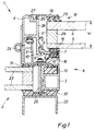
- Fig. 1
- einen schematischen Vertikalschnitt durch ein Glasdach im Bereich der Anlenkung eines Klappflügels, und
- Fig. 2
- eine weitere Ausführungsvariante eines Klappflügels in einem Vertikalschnitt entsprechend Fig. 1.
- Fig. 1
- a schematic vertical section through a glass roof in the region of the articulation of a folding wing, and
- Fig. 2
- a further embodiment of a folding wing in a vertical section corresponding to FIG. 1.
Gemäß Zeichnung ist ein Sparren 22 als Teil einer tragenden Glasbaukonstruktion aus parallel zueinander geneigt angeordneten Sparren und rechtwinklig zu diesen waagrecht verlaufenden Pfetten vorgesehen. Die durch Sparren und Pfetten gebildeten Feldern sind überdeckt von Glasscheiben 23, die zusammen ein Glasdach 2 ausbilden.According to the drawing, a
An einer oder mehreren Stellen des Glasdachs 2 sind keine festen Glasscheiben 23 vorgesehen, sondern Klappflügel 1 mit einem Klappflügelrahmen 4, der direkt über einem Festrahmen 3, 3' der Öffnung des Glasdachs 2 schwenkbar angelenkt ist, und zwar durch ein oder mehrere horizontale Schwenkgelenke 24 mit gleicher axialer Erstreckungsrichtung. Der Festrahmen oder Blendrahmen 3, 3' ist durch vertikale Bolzen 25 mit dem Sparren 22 verschraubt, wobei eine untere Abdichtschiene 30 und eine obere Abdichtschiene 31 vorgesehen sind.Fixed
Der Klappflügelrahmen 4 besitzt ein oberes Schwenkteil 26 mit zwei Aussparungen 11, 11' an unterer Stelle und einer weiteren Aussparung 27 an oberer Stelle. In der unteren Aussparung 11 ist die untere Abstützungsleiste 9 in einhängender Weise formschlüssig befestigt, auf deren randinnerer Abdichtung die untere Scheibe 5 in einem Verbund mit der oberen Scheibe 6 des Klappflügels 1 unter Zwischenordnung einer Distanzleiste 28 auflastet.The
Für eine Montage eines Klappflügels 1 wird vorab der Klappflügelrahmen 4 am Festrahmen 3, 3' schwenkbar angelenkt. Bevor die Klappflügelscheiben 5, 6 montiert werden, wird die untere Abstützungsleiste 9 in der Aussparung 11 eingehakt, deren Abdichtung sich mit der unteren Abdichtfläche 16 satt auf dem Öffnungsrahmen 3 abstützt. Gegebenenfalls muß der Klappflügelrahmen 4 samt Abstützungsleiste 9 nach unten verschoben werden, damit die Dichtigkeit bei der unteren Abdichtfläche 16 gewährleistet ist. Hiernach wird der verklebte Scheibenverbund bestehend aus oberer Scheibe 6 und unterer Scheibe 5 mit zwischengeordneter Distanzleiste 28 von oben in den Klappflügelrahmen 4 eingesetzt, so daß die Unterseite des Rands der unteren Scheibe 5 satt in abgedichteter Weise auf der oberen Abdichtfläche 15 der unteren Abstützungsleiste 9 aufliegt. Anschließend wird die obere separate Stützleiste 19 ohne Abdichtung 29 mit ihrem Hakenteil 20 in die Aussparung 27 eingehakt. Die Aussparung 27 ist so getroffen, daß die separate obere Stützleiste 19 nicht im Gegenuhrzeigersinn gemäß Fig. 1 geschwenkt werden kann, vielmehr in der gezeigten horizontalen Stellung bezüglich des geschlossenen Klappflügelrahmens 4 arretiert ist. In dieser arretierten Horizontalstellung wird schließlich die obere Abdichtung 29 seitlich, d.h. senkrecht zur Zeichenebene eingeführt, so daß insgesamt ein Preßsitz der Scheiben 5 und 6 zwischen den Abdichtungen 29 und 15 entsteht. Ein derartig verspannter Klappflügel 1 kann im Gegenuhrzeigersinn gemäß Fig. 1 um das Schwenkgelenk 24 geöffnet werden.For the assembly of a folding leaf 1, the
Insbesondere sind neben der unteren Aussparung 11 des Schwenkteils 26 mit Abstand weitere Aussparungen 11' an oberer Stelle vorgesehen, welche gleich dimensioniert sind. In diese Aussparungen 11' kann das Hakenteil 10 der unteren Abstützungsleiste 9 eingesetzt werden, wenn ein oder mehrere Scheiben 5 bzw. 6 geringerer Dicke d in den Klappflügelrahmen 4 eingesetzt werden sollen.In particular, in addition to the
Die Abstützungsleiste 9 weist bezüglich ihrer Längserstreckung einen Versetzungsabschnitt 9' auf, und es ist das Hakenteil bezüglich der Längsachse der Abstützungsleiste symmetrisch, so daß das Hakenteil in jeder Aussparung 11 bzw. 11' in zwei unterschiedlichen, um 180° versetzten Stellungen formschlüssig eingehängt werden kann. Dadurch kann weiteren anderen Scheibendicken Rechnung getragen werden.The
Um eine dünnere Scheibenkonstruktion nicht nur beim Klappflügel 1, sondern auch bei dem Rest des Glasdachs bei den Glasscheiben 23 zu realisieren, ist eine weitere Verstelleinrichtung 8 des Öffnungsrahmens 3 vorgesehen, insbesondere durch Ausbildung eines Abstandshalters 12 aus Kunststoff, welcher bei dünneren Scheibenkonstruktionen gegebenenfalls entfernt oder durch weniger dicke Abstandshalter ersetzt werden kann. Dadurch kann die Gesamtkonstruktion in der Höhe noch flacher konzipiert werden. Der obere Klappflügelrahmen 4 wandert durch Weglassung des Abstandshalters 12 weiter nach unten. Das in Fig. 2 gezeigte Ausführungsbeispiel entspricht im wesentlichen demjenigen nach Fig.1. Anstelle der Aussparungen 11, 11' des ersten Ausführungsbeispiels ist hier jedoch ein anderer Verstellmechanismus der unteren Scheibenabstützung 7 vorgesehen, und zwar in Form eines zwischengeordneten Abstandshalters 14 mit zugehöriger Schraubverbindung 13 in Richtung Schwenkteil 26. Sind schlankere Glasscheiben 5, 6 eines Klappflügels 1 zu montieren, wird ein entsprechend schlanker Abstandshalter 14 durch die Schraubverbindung 13 montiert, so daß wieder ein fester Glasscheibenverbund 5, 6 eines Klappflügels 1 gegeben ist. Auch der untere Abstandshalter 12 kann schlanker dimensioniert, d.h. der in der Fig. 2 gezeigte durch einen weniger dicken ausgetauscht werden, um Glasscheiben 23 mit einer geringeren Dicke vorzusehen.In order to realize a thinner pane construction not only with the folding wing 1, but also with the rest of the glass roof with the
Die Ausführungsvariante nach Fig. 2 besitzt eine obere Scheibenabstützung 18 in Form einer Glasleiste 21, die integriert mit dem Schwenkteil 26 ausgebildet ist. Jedoch kann auch eine separate obere Scheibenabstützung 18 vorgesehen sein, deren Basis ein Hakenteil 20 nach Art der ersten Ausführungsvariante besitzt.The embodiment variant according to FIG. 2 has an
Um den Klappflügel 1 zu montieren, wird der nichtangelenkte Klappflügelrahmen 4 um 180° gedreht, so daß die obere Scheibenabstützung 18 unten zu liegen kommt. Auf der Abdichtung 29 wird nun der verklebte Scheibenverbund 5, 6 des Klappflügels satt aufgesetzt und anschließend der Abstandshalter 14 nebst unterer Scheibenabstützung 7 verschraubt. Ein derartig verschraubter Schwenkteil eines Klappflügels 1 wird dann in der in Fig. 2 gezeigten Stellung am Schwenkgelenk 24 befestigt.In order to assemble the folding wing 1, the non-articulated folding
Es sei noch angemerkt, daß in den Unteransprüchen enthaltene selbständig schutzfähige Merkmale trotz der vorgenommenen formalen Rückbeziehung auf den Hauptanspruch entsprechenden eigenständigen Schutz haben sollen. Im übrigen fallen sämtliche in den gesamten Anmeldungsunterlagen enthaltenen erfinderischen Merkmale in den Schutzumfang der ErfindungIt should also be noted that, despite the formal reference back to the main claim, the independently protectable features contained in the subclaims should have appropriate independent protection. For the rest, all inventive features contained in the entire application documents fall within the scope of the invention
Claims (12)
dadurch gekennzeichnet,
daß der Klappflügelrahmen (4) eine untere bzw. rauminnere, die Scheibendicke (d) verstellbare Scheibenabstützung (7) aufweist.Folding sash (1) of a glass roof (2), a glass wall or a corresponding plastic or metal construction, with a hinged hinged sash frame (4), which is placed on a fixed frame (3, 3 ') of the opening of the glass roof (2), in which a or several (glass) panes (5, 6) are enclosed in a sealed manner,
characterized,
that the folding sash frame (4) has a lower or inner space, the pane thickness (d) adjustable pane support (7).
dadurch gekennzeichnet,
daß der Festrahmen (3, 3') eine die Scheibendicke des Glasdachs (2) verstellbare weitere Verstelleinrichtung (8) aufweist.Folding wing according to claim 1,
characterized,
that the fixed frame (3, 3 ') has a further adjusting device (8) which can be adjusted to the pane thickness of the glass roof (2).
dadurch gekennzeichnet,
daß die untere Scheibenabstützung (7) eine Abstützungsleiste (9) umfaßt, deren Basis ein Hakenteil (10) ist, welches entsprechend einer bestimmten Scheibendicke (d) des Klappflügels (1) in zugeordneten Aussparungen (11, 11') des Klappflügelrahmens (4) formschlüssig einhängbar und im montierten Zustand der Anordnung satt in der zugeordneten Aussparung (11 bzw. 11') befestigt ist (Fig.1).Folding wing according to claim 1 or 2,
characterized,
that the lower pane support (7) comprises a support strip (9), the base of which is a hook part (10) which, in accordance with a certain pane thickness (d) of the folding leaf (1), in associated recesses (11, 11 ') of the folding leaf frame (4) can be positively hooked in and in the assembled state of the arrangement is securely fastened in the associated recess (11 or 11 ') (FIG. 1).
dadurch gekennzeichnet,
daß die Abstützungsleiste (9) bezüglich ihrer Längserstreckung einen Versetzungsabschnitt (9') und ein zu ihrer Längsachse symmtrisches Hakenteil (10) aufweist, welches in den Aussparungen (11, 11') in zwei bezüglich der Längssachse um 180° versetzten unterschiedlichen Stellungen formschlüssig einhängbar ist.Folding wing according to claim 3,
characterized,
that the support strip (9) has a displacement section (9 ') with respect to its longitudinal extent and a hook part (10) symmetrical to its longitudinal axis, which can be positively hooked into the recesses (11, 11 ') in two different positions offset by 180 ° with respect to the longitudinal axis.
dadurch gekennzeichnet,
daß die untere Scheibenabstützung (7) eine Abstützungsleiste (9) umfaßt, deren plane Basis eine Schraubverbindung (13) mit einem Abstandshalter (14) zum restlichen Klappflügelrahmen (4) aufweist.Folding wing according to claim 1 or 2,
characterized,
that the lower pane support (7) comprises a support strip (9), the flat base of which has a screw connection (13) with a spacer (14) to the rest of the folding casement (4).
dadurch gekennzeichnet,
daß die weitere Verstelleinrichtung (8) eine Schraub- bzw. Klemmverbindung (25) aufweist.Folding wing according to claim 5,
characterized,
that the further adjusting device (8) has a screw or clamp connection (25).
dadurch gekennzeichnet,
daß die untere Abstützungsleiste (9) eine obere Abdichtfläche (15) zur Klappflügelscheibe (5) und eine untere Abdichtfläche (16) zum Festrahmen (3, 3') aufweist.Folding wing according to one of claims 1 to 6,
characterized,
that the lower support bar (9) has an upper sealing surface (15) to the folding wing disc (5) and a lower sealing surface (16) to the fixed frame (3, 3 ').
dadurch gekennzeichnet,
daß die untere Abstützungsleiste (9) eine einzige Abdichtung aufweist (Fig. 1).Folding wing according to claim 7,
characterized,
that the lower support bar (9) has a single seal (Fig. 1).
dadurch gekennzeichnet,
daß die einzige Abdichtung eine weitere Abdichtlippe (17) besitzt.Folding wing according to claim 8,
characterized,
that the only seal has a further sealing lip (17).
dadurch gekennzeichnet,
daß der Klappflügelrahmen (4) eine obere Scheibenabstützung (18) mit einer separaten Stützleiste (19) aufweist, deren Basis ein Hakenteil (20) nach Art der unteren Abstützungsleiste (9) umfaßt und im restlichen Klappflügelrahmen (4) formschlüssig einhängbar und satt befestigbar ist.Folding wing according to one of claims 3 to 9,
characterized,
that the folding casement (4) has an upper pane support (18) with a separate support strip (19), the base of which comprises a hook part (20) in the manner of the lower support strip (9) and can be positively hooked in and securely fastened in the remaining folding sash frame (4).
dadurch gekennzeichnet,
daß der Abstandshalter (14) sowie die Abstandshalteleiste (12) aus einem wärmeisolierenden Material, insbesondere aus Kunststoff, ausgebildet sind.Folding wing according to one of claims 4 to 10,
characterized,
that the spacer (14) and the spacer bar (12) are made of a heat-insulating material, in particular plastic.
dadurch gekennzeichnet,
daß der Festrahmen (3, 3') eine obere, über das ganzeGlasdach gehende Abdichtschiene (31) aufweist.Folding wing according to one of claims 1 to 11,
characterized,
that the fixed frame (3, 3 ') has an upper sealing rail (31) extending over the entire glass roof.
Applications Claiming Priority (2)
| Application Number | Priority Date | Filing Date | Title |
|---|---|---|---|
| DE29505023U | 1995-03-24 | ||
| DE29505023U DE29505023U1 (en) | 1995-03-24 | 1995-03-24 | Folding wing of a glass roof, a glass wall or a corresponding plastic or metal structure |
Publications (2)
| Publication Number | Publication Date |
|---|---|
| EP0733767A2 true EP0733767A2 (en) | 1996-09-25 |
| EP0733767A3 EP0733767A3 (en) | 1997-01-22 |
Family
ID=8005833
Family Applications (1)
| Application Number | Title | Priority Date | Filing Date |
|---|---|---|---|
| EP96103137A Withdrawn EP0733767A3 (en) | 1995-03-24 | 1996-03-01 | Tiltable window of a glazed roof, a glazed wall or a similar construction made of plastics or metal |
Country Status (2)
| Country | Link |
|---|---|
| EP (1) | EP0733767A3 (en) |
| DE (1) | DE29505023U1 (en) |
Cited By (2)
| Publication number | Priority date | Publication date | Assignee | Title |
|---|---|---|---|---|
| WO2004083552A1 (en) * | 2003-03-21 | 2004-09-30 | Burnden Holdings (Uk) Limited | Improvements in and relating to roof vents |
| CN105649280A (en) * | 2015-12-28 | 2016-06-08 | 山东华信塑胶股份有限公司 | Sunlight room skylight system and manufacturing method thereof |
Families Citing this family (4)
| Publication number | Priority date | Publication date | Assignee | Title |
|---|---|---|---|---|
| EP0833017B1 (en) * | 1996-08-27 | 2002-07-31 | Eternit Flachdach Gmbh | Roof element with a fastening device |
| US9683402B2 (en) | 2004-07-15 | 2017-06-20 | City Glass & Glazing (P) Ltd. | Glazing system with thermal break |
| CN1693648B (en) * | 2005-05-31 | 2012-01-25 | 杨俊普 | Hanging type sliding sash |
| US9243709B2 (en) | 2013-03-14 | 2016-01-26 | Mahle International Gmbh | Welded piston assembly |
Citations (8)
| Publication number | Priority date | Publication date | Assignee | Title |
|---|---|---|---|---|
| FR1275930A (en) * | 1960-12-12 | 1961-11-10 | Prefabricated strip, possibly removable and sealing by self-tightening, for installing windows, mirrors, panels | |
| DE2113691A1 (en) * | 1971-03-22 | 1972-11-30 | Beck Stahlbau Fertigbau H | Frame profile for window or facade strips |
| DE2300358A1 (en) * | 1973-01-04 | 1974-07-11 | Schoeninger Gmbh | SEAL ARRANGEMENT FOR WINDOWS AND DOORS |
| DE2354807A1 (en) * | 1973-11-02 | 1975-05-07 | Dynamit Nobel Ag | Sealed window wing frame - has sealing profiles holding pane between flange and frame fixed by holding pins |
| DE2532172A1 (en) * | 1975-07-18 | 1977-01-20 | Glas & Spiegel Manufactur Ag | Glass partition with opening window - has glass U-sections fitting in corresponding metal parts with securing slides |
| NL7802934A (en) * | 1978-03-17 | 1979-09-19 | Braat Bouwstoffen Nv | Fire protection equipment smoke release hatch - has detector coupled to spring for initial opening until actuator can operate fully |
| DE4141994A1 (en) * | 1991-12-19 | 1993-06-24 | Gerd Philippi | FOLDING LEAF OF A GLASS ROOF OR GLASS WALL |
| DE4339467C1 (en) * | 1993-11-19 | 1995-03-23 | Herbert Lacker | Roof-glazing system |
-
1995
- 1995-03-24 DE DE29505023U patent/DE29505023U1/en not_active Expired - Lifetime
-
1996
- 1996-03-01 EP EP96103137A patent/EP0733767A3/en not_active Withdrawn
Patent Citations (8)
| Publication number | Priority date | Publication date | Assignee | Title |
|---|---|---|---|---|
| FR1275930A (en) * | 1960-12-12 | 1961-11-10 | Prefabricated strip, possibly removable and sealing by self-tightening, for installing windows, mirrors, panels | |
| DE2113691A1 (en) * | 1971-03-22 | 1972-11-30 | Beck Stahlbau Fertigbau H | Frame profile for window or facade strips |
| DE2300358A1 (en) * | 1973-01-04 | 1974-07-11 | Schoeninger Gmbh | SEAL ARRANGEMENT FOR WINDOWS AND DOORS |
| DE2354807A1 (en) * | 1973-11-02 | 1975-05-07 | Dynamit Nobel Ag | Sealed window wing frame - has sealing profiles holding pane between flange and frame fixed by holding pins |
| DE2532172A1 (en) * | 1975-07-18 | 1977-01-20 | Glas & Spiegel Manufactur Ag | Glass partition with opening window - has glass U-sections fitting in corresponding metal parts with securing slides |
| NL7802934A (en) * | 1978-03-17 | 1979-09-19 | Braat Bouwstoffen Nv | Fire protection equipment smoke release hatch - has detector coupled to spring for initial opening until actuator can operate fully |
| DE4141994A1 (en) * | 1991-12-19 | 1993-06-24 | Gerd Philippi | FOLDING LEAF OF A GLASS ROOF OR GLASS WALL |
| DE4339467C1 (en) * | 1993-11-19 | 1995-03-23 | Herbert Lacker | Roof-glazing system |
Cited By (3)
| Publication number | Priority date | Publication date | Assignee | Title |
|---|---|---|---|---|
| WO2004083552A1 (en) * | 2003-03-21 | 2004-09-30 | Burnden Holdings (Uk) Limited | Improvements in and relating to roof vents |
| CN105649280A (en) * | 2015-12-28 | 2016-06-08 | 山东华信塑胶股份有限公司 | Sunlight room skylight system and manufacturing method thereof |
| CN105649280B (en) * | 2015-12-28 | 2018-03-13 | 山东华信塑胶股份有限公司 | A kind of glass sunlight house retractable roof system and its manufacture method |
Also Published As
| Publication number | Publication date |
|---|---|
| DE29505023U1 (en) | 1995-06-22 |
| EP0733767A3 (en) | 1997-01-22 |
Similar Documents
| Publication | Publication Date | Title |
|---|---|---|
| DE69913674T2 (en) | ROOF WINDOW WITH FRAME AND LEAF COVERING ELEMENTS | |
| DE202007018335U1 (en) | Composite frame for insertion into a building opening | |
| EP2666948B1 (en) | Frame assembly for a panel for sectional doors | |
| EP0658662B1 (en) | Glass-façade with window | |
| EP1431501A2 (en) | Sliding door assembly | |
| DE3509466C2 (en) | ||
| EP0785335A1 (en) | Holding device for glazing pane edge | |
| EP0733767A2 (en) | Tiltable window of a glazed roof, a glazed wall or a similar construction made of plastics or metal | |
| EP0450289B1 (en) | Composite wooden and metal frame for windows, doors and the like | |
| EP1067268A2 (en) | Window system with a window pane and an extruded section member | |
| EP1136644B1 (en) | Window or door with fixed and wing frame and a glazing panel | |
| EP0730068B1 (en) | Skylight | |
| WO2001059244A1 (en) | Window/door system | |
| DE4339467C1 (en) | Roof-glazing system | |
| DE19855028B4 (en) | Skylight constructions | |
| EP0702124B1 (en) | Finger guard for sectional doors | |
| EP3581752B1 (en) | Window | |
| DE19912900C1 (en) | Covering panels for a wall or roof are mounted on hinged supports fitted to mounting rails | |
| DE3535891C2 (en) | Skylight windows or facade windows | |
| DE69816740T2 (en) | Wall element made of a profile frame and double glazing with step edge | |
| DE4408916A1 (en) | Anti-break-in window | |
| AT1339U1 (en) | WINDOW | |
| EP0497315A1 (en) | Wall or roof surfaces made of glass panes | |
| DE2013319B2 (en) | Swing or turning door or window sealing - comprises mutually offset sealing bars joined into Z=shaped strip by cross member (OE 15.8.75) | |
| EP0730078A2 (en) | Tiltable wing for glazing contructions or the like |
Legal Events
| Date | Code | Title | Description |
|---|---|---|---|
| PUAI | Public reference made under article 153(3) epc to a published international application that has entered the european phase |
Free format text: ORIGINAL CODE: 0009012 |
|
| AK | Designated contracting states |
Kind code of ref document: A2 Designated state(s): AT CH DE FR LI |
|
| PUAL | Search report despatched |
Free format text: ORIGINAL CODE: 0009013 |
|
| AK | Designated contracting states |
Kind code of ref document: A3 Designated state(s): AT CH DE FR LI |
|
| RAP1 | Party data changed (applicant data changed or rights of an application transferred) |
Owner name: J. EBERSPAECHER GMBH & CO. |
|
| 17P | Request for examination filed |
Effective date: 19970523 |
|
| STAA | Information on the status of an ep patent application or granted ep patent |
Free format text: STATUS: THE APPLICATION HAS BEEN WITHDRAWN |
|
| 18W | Application withdrawn |
Withdrawal date: 19980219 |