EP2666948B1 - Frame assembly for a panel for sectional doors - Google Patents
Frame assembly for a panel for sectional doors Download PDFInfo
- Publication number
- EP2666948B1 EP2666948B1 EP13002491.2A EP13002491A EP2666948B1 EP 2666948 B1 EP2666948 B1 EP 2666948B1 EP 13002491 A EP13002491 A EP 13002491A EP 2666948 B1 EP2666948 B1 EP 2666948B1
- Authority
- EP
- European Patent Office
- Prior art keywords
- profile
- sectional door
- groove
- door according
- frame
- Prior art date
- Legal status (The legal status is an assumption and is not a legal conclusion. Google has not performed a legal analysis and makes no representation as to the accuracy of the status listed.)
- Active
Links
Images


Classifications
-
- E—FIXED CONSTRUCTIONS
- E06—DOORS, WINDOWS, SHUTTERS, OR ROLLER BLINDS IN GENERAL; LADDERS
- E06B—FIXED OR MOVABLE CLOSURES FOR OPENINGS IN BUILDINGS, VEHICLES, FENCES OR LIKE ENCLOSURES IN GENERAL, e.g. DOORS, WINDOWS, BLINDS, GATES
- E06B3/00—Window sashes, door leaves, or like elements for closing wall or like openings; Layout of fixed or moving closures, e.g. windows in wall or like openings; Features of rigidly-mounted outer frames relating to the mounting of wing frames
- E06B3/04—Wing frames not characterised by the manner of movement
- E06B3/263—Frames with special provision for insulation
- E06B3/26301—Frames with special provision for insulation with prefabricated insulating strips between two metal section members
- E06B3/26303—Frames with special provision for insulation with prefabricated insulating strips between two metal section members with thin strips, e.g. defining a hollow space between the metal section members
-
- E—FIXED CONSTRUCTIONS
- E06—DOORS, WINDOWS, SHUTTERS, OR ROLLER BLINDS IN GENERAL; LADDERS
- E06B—FIXED OR MOVABLE CLOSURES FOR OPENINGS IN BUILDINGS, VEHICLES, FENCES OR LIKE ENCLOSURES IN GENERAL, e.g. DOORS, WINDOWS, BLINDS, GATES
- E06B3/00—Window sashes, door leaves, or like elements for closing wall or like openings; Layout of fixed or moving closures, e.g. windows in wall or like openings; Features of rigidly-mounted outer frames relating to the mounting of wing frames
- E06B3/54—Fixing of glass panes or like plates
- E06B3/58—Fixing of glass panes or like plates by means of borders, cleats, or the like
- E06B3/5807—Fixing of glass panes or like plates by means of borders, cleats, or the like not adjustable
- E06B3/5821—Fixing of glass panes or like plates by means of borders, cleats, or the like not adjustable hooked on or in the frame member, fixed by clips or otherwise elastically fixed
-
- E—FIXED CONSTRUCTIONS
- E06—DOORS, WINDOWS, SHUTTERS, OR ROLLER BLINDS IN GENERAL; LADDERS
- E06B—FIXED OR MOVABLE CLOSURES FOR OPENINGS IN BUILDINGS, VEHICLES, FENCES OR LIKE ENCLOSURES IN GENERAL, e.g. DOORS, WINDOWS, BLINDS, GATES
- E06B3/00—Window sashes, door leaves, or like elements for closing wall or like openings; Layout of fixed or moving closures, e.g. windows in wall or like openings; Features of rigidly-mounted outer frames relating to the mounting of wing frames
- E06B3/68—Window bars
-
- E—FIXED CONSTRUCTIONS
- E06—DOORS, WINDOWS, SHUTTERS, OR ROLLER BLINDS IN GENERAL; LADDERS
- E06B—FIXED OR MOVABLE CLOSURES FOR OPENINGS IN BUILDINGS, VEHICLES, FENCES OR LIKE ENCLOSURES IN GENERAL, e.g. DOORS, WINDOWS, BLINDS, GATES
- E06B3/00—Window sashes, door leaves, or like elements for closing wall or like openings; Layout of fixed or moving closures, e.g. windows in wall or like openings; Features of rigidly-mounted outer frames relating to the mounting of wing frames
- E06B3/96—Corner joints or edge joints for windows, doors, or the like frames or wings
- E06B3/9636—Corner joints or edge joints for windows, doors, or the like frames or wings for frame members having longitudinal screw receiving channels
-
- E—FIXED CONSTRUCTIONS
- E06—DOORS, WINDOWS, SHUTTERS, OR ROLLER BLINDS IN GENERAL; LADDERS
- E06B—FIXED OR MOVABLE CLOSURES FOR OPENINGS IN BUILDINGS, VEHICLES, FENCES OR LIKE ENCLOSURES IN GENERAL, e.g. DOORS, WINDOWS, BLINDS, GATES
- E06B3/00—Window sashes, door leaves, or like elements for closing wall or like openings; Layout of fixed or moving closures, e.g. windows in wall or like openings; Features of rigidly-mounted outer frames relating to the mounting of wing frames
- E06B3/04—Wing frames not characterised by the manner of movement
- E06B3/263—Frames with special provision for insulation
- E06B2003/26349—Details of insulating strips
- E06B2003/2635—Specific form characteristics
- E06B2003/26358—Specific form characteristics stepped or undulated
-
- E—FIXED CONSTRUCTIONS
- E06—DOORS, WINDOWS, SHUTTERS, OR ROLLER BLINDS IN GENERAL; LADDERS
- E06B—FIXED OR MOVABLE CLOSURES FOR OPENINGS IN BUILDINGS, VEHICLES, FENCES OR LIKE ENCLOSURES IN GENERAL, e.g. DOORS, WINDOWS, BLINDS, GATES
- E06B3/00—Window sashes, door leaves, or like elements for closing wall or like openings; Layout of fixed or moving closures, e.g. windows in wall or like openings; Features of rigidly-mounted outer frames relating to the mounting of wing frames
- E06B3/04—Wing frames not characterised by the manner of movement
- E06B3/263—Frames with special provision for insulation
- E06B2003/26349—Details of insulating strips
- E06B2003/2635—Specific form characteristics
- E06B2003/26359—Specific form characteristics making flush mounting with neighbouring metal section members possible
-
- E—FIXED CONSTRUCTIONS
- E06—DOORS, WINDOWS, SHUTTERS, OR ROLLER BLINDS IN GENERAL; LADDERS
- E06B—FIXED OR MOVABLE CLOSURES FOR OPENINGS IN BUILDINGS, VEHICLES, FENCES OR LIKE ENCLOSURES IN GENERAL, e.g. DOORS, WINDOWS, BLINDS, GATES
- E06B3/00—Window sashes, door leaves, or like elements for closing wall or like openings; Layout of fixed or moving closures, e.g. windows in wall or like openings; Features of rigidly-mounted outer frames relating to the mounting of wing frames
- E06B3/04—Wing frames not characterised by the manner of movement
- E06B3/263—Frames with special provision for insulation
- E06B2003/26349—Details of insulating strips
- E06B2003/2635—Specific form characteristics
- E06B2003/26361—Openings, incisions or indents
-
- E—FIXED CONSTRUCTIONS
- E06—DOORS, WINDOWS, SHUTTERS, OR ROLLER BLINDS IN GENERAL; LADDERS
- E06B—FIXED OR MOVABLE CLOSURES FOR OPENINGS IN BUILDINGS, VEHICLES, FENCES OR LIKE ENCLOSURES IN GENERAL, e.g. DOORS, WINDOWS, BLINDS, GATES
- E06B3/00—Window sashes, door leaves, or like elements for closing wall or like openings; Layout of fixed or moving closures, e.g. windows in wall or like openings; Features of rigidly-mounted outer frames relating to the mounting of wing frames
- E06B3/04—Wing frames not characterised by the manner of movement
- E06B3/263—Frames with special provision for insulation
- E06B2003/26349—Details of insulating strips
- E06B2003/2635—Specific form characteristics
- E06B2003/26363—Screw channels
-
- E—FIXED CONSTRUCTIONS
- E06—DOORS, WINDOWS, SHUTTERS, OR ROLLER BLINDS IN GENERAL; LADDERS
- E06B—FIXED OR MOVABLE CLOSURES FOR OPENINGS IN BUILDINGS, VEHICLES, FENCES OR LIKE ENCLOSURES IN GENERAL, e.g. DOORS, WINDOWS, BLINDS, GATES
- E06B3/00—Window sashes, door leaves, or like elements for closing wall or like openings; Layout of fixed or moving closures, e.g. windows in wall or like openings; Features of rigidly-mounted outer frames relating to the mounting of wing frames
- E06B3/04—Wing frames not characterised by the manner of movement
- E06B3/263—Frames with special provision for insulation
- E06B2003/26349—Details of insulating strips
- E06B2003/26369—Specific material characteristics
- E06B2003/2637—Specific material characteristics reinforced
-
- E—FIXED CONSTRUCTIONS
- E06—DOORS, WINDOWS, SHUTTERS, OR ROLLER BLINDS IN GENERAL; LADDERS
- E06B—FIXED OR MOVABLE CLOSURES FOR OPENINGS IN BUILDINGS, VEHICLES, FENCES OR LIKE ENCLOSURES IN GENERAL, e.g. DOORS, WINDOWS, BLINDS, GATES
- E06B3/00—Window sashes, door leaves, or like elements for closing wall or like openings; Layout of fixed or moving closures, e.g. windows in wall or like openings; Features of rigidly-mounted outer frames relating to the mounting of wing frames
- E06B3/04—Wing frames not characterised by the manner of movement
- E06B3/263—Frames with special provision for insulation
- E06B2003/26349—Details of insulating strips
- E06B2003/26387—Performing extra functions
-
- E—FIXED CONSTRUCTIONS
- E06—DOORS, WINDOWS, SHUTTERS, OR ROLLER BLINDS IN GENERAL; LADDERS
- E06B—FIXED OR MOVABLE CLOSURES FOR OPENINGS IN BUILDINGS, VEHICLES, FENCES OR LIKE ENCLOSURES IN GENERAL, e.g. DOORS, WINDOWS, BLINDS, GATES
- E06B3/00—Window sashes, door leaves, or like elements for closing wall or like openings; Layout of fixed or moving closures, e.g. windows in wall or like openings; Features of rigidly-mounted outer frames relating to the mounting of wing frames
- E06B3/04—Wing frames not characterised by the manner of movement
- E06B3/263—Frames with special provision for insulation
- E06B2003/26392—Glazing bars
-
- E—FIXED CONSTRUCTIONS
- E06—DOORS, WINDOWS, SHUTTERS, OR ROLLER BLINDS IN GENERAL; LADDERS
- E06B—FIXED OR MOVABLE CLOSURES FOR OPENINGS IN BUILDINGS, VEHICLES, FENCES OR LIKE ENCLOSURES IN GENERAL, e.g. DOORS, WINDOWS, BLINDS, GATES
- E06B3/00—Window sashes, door leaves, or like elements for closing wall or like openings; Layout of fixed or moving closures, e.g. windows in wall or like openings; Features of rigidly-mounted outer frames relating to the mounting of wing frames
- E06B3/32—Arrangements of wings characterised by the manner of movement; Arrangements of movable wings in openings; Features of wings or frames relating solely to the manner of movement of the wing
- E06B3/48—Wings connected at their edges, e.g. foldable wings
- E06B3/485—Sectional doors
Definitions
- the invention relates to a sectional door according to the preamble of patent claim 1.
- Sectional doors are used to close garage and hall openings. They have a door leaf movable along a guide rail arrangement between an open position and a closed position.
- the door leaf consists of a plurality of respect. With respect to the direction of movement extending hinge axes against each other pivotable Se Erasmusaltorpaneelen.
- This Torblattkonstrutation allows an opening and closing movement along the guide rail assembly without pivoting of the door leaf in the space thus to be closed off the area because the Torblattpaneele rest along an arcuate guide rail area and can be tilted against each other.
- the guide rails are regular a first guide rail section running rectilinearly and in the direction of gravity, a second guide rail section running in a straight line and substantially in the horizontal direction, and a curved guide rail section interconnecting the two linearly extending guide rail sections.
- the horizontal guide rail area is usually arranged overhead, so that the Se Erasmusaltorblatt can be arranged in the open position above the head approximately in a horizontal plane, while it is arranged in the closed position approximately in a vertical plane.
- the panels of such door leaves can be designed as so-called sandwich constructions in which an insulating foam core is accommodated between two metal shells.
- Corresponding Sedgingaltorblattpaneele are, for example, in the EP 0 370 376 described. The disclosure of this document is hereby expressly incorporated into this description with regard to the construction of sectional aluminum panels, in particular with regard to their edge profiles.
- the individual frame profiles are connected to one another via two plastic strips, that is to say connecting elements made of a thermally insulating material.
- two transparent discs having filling can be used. This filling is usually on a seal assembly on a positioning web of the outer profile and can be locked there with the help of a filling engaging under holding device.
- the individual frame profiles are common, as well as the Holding device, to obtain a satisfactory overall stability made of a metallic material, esp. Executed as aluminum extruded profiles.
- insulating frame arrangements for doors and windows are described.
- EP 1 256 685 A2 a folding door is described with two or more mutually hinged Torfeldern, each of which has a support frame, which is made of frame profiles, wherein on the outside of the door trim strips are provided, which are clipped on at least one held on the frame profile insulating insert, and a the clear space of the support frame covering filling is held on the support frame.
- the invention has for its object to provide a sectional door with improved thermal separation between the interior and exterior.
- the invention is based on the knowledge that the problems observed in the prior art are essentially due to the heat or cold bridges provided by the holding device.
- a direct heat transfer between the outer and the inner profile of the frame assembly is prevented via the holding device, because the holding device can be coupled by avoiding simultaneous contact with two profiles of the frame assembly on the coupling device to the connecting device of thermally insulating material.
- a satisfactory thermal separation between exterior and interior is achieved with frame arrangements according to the invention.
- the coupling device integrally with a extending between the inner and the outer profile and preferably both on the inner and on the outer profile fastened connecting element of the connecting device is formed.
- the connecting element can be made entirely of plastic together with the coupling device, for example as a plastic extruded profile.
- the depth direction of the groove extending from the groove bottom in the direction of the groove opening therefore extends approximately perpendicular to the outside or inside of the frame.
- a groove wall may be formed by the filling surface facing the boundary surface of the connecting element. If this groove wall is flush with an adjoining support surface of the groove opening facing profile, preferably the inner profile, esp. Coplanar is designed so that the insertion of the retaining strip of the holding device is favored in the groove.
- the insertion of the retaining strip in the groove can be further facilitated without affecting the holding properties, when the groove tapers, starting from the groove opening in the direction of the groove bottom in a direction approximately perpendicular to the groove wall formed by the filling facing boundary surface of the connecting element.
- the groove width can remain constant in sections, so as to secure a stable coupling of the holding device to the connecting element.
- the retaining strip can be clamped with appropriate dimensioning between retaining web and coupling groove. It has proven to be favorable in terms of a particularly stable locking of the retaining strip when between holding web and support surface is open in the direction of the coupling groove holding groove for receiving a retaining lug on the side facing away from the coupling groove of the holding device or retaining strip.
- the connecting element is positively connected to at least one profile.
- a connecting edge of the connecting element extending in the longitudinal direction of a profile is thickened and received in a connecting groove of the profile.
- the connecting element is designed cranked. It has proved to be particularly favorable when the connecting element on opposite sides of the coupling groove in each case falls away in a direction away from the filling and terminates in a respective thickened connecting edge.
- the stability of the attachment of the holding device to the coupling device of the connecting element is further improved according to the invention that the connecting element in the region of its boundary surface facing away from the coupling device at least one extending in one of the filling direction extending and designed for supporting on a support bar of a profile supporting projection.
- the connecting device has at least one further, approximately parallel to the equipped with the coupling device connecting element, preferably connected at its opposite edges, each with a profile connecting element.
- the further connecting element can be designed cranked in terms of increasing the overall stability, and it can fall off in a direction away from its each received in a holding groove, preferably hidden edges in a filling direction to a central region.
- a connection or stabilization rung of a frame produced from a frame arrangement according to the invention arranged in the region of the filling usually becomes attached to the frame assembly with suitable fastening bolts or bolts. It has proved to be particularly useful in terms of increasing the overall stability while avoiding impairment of the thermal separation, if at least one profile of a frame assembly according to the invention has a support web with an applied for applying a bolt head thereto, the filling facing away from contact surface.
- the individual profiles of the frame assembly are thermally coupled to one another not only via the connecting elements, but also via the bolt head of the fastening bolt.
- the cross-section of a corresponding bolt head is, however, regularly made so low that the heat conduction over the bolt head is negligible and can be readily accepted in view of the stability increase achieved by the installation of the bolt head on the contact surface.
- a secure fixing of the filling to the frame assembly can be achieved if at least one connecting element has a recess penetrated by the fastening bolt, wherein the bolt head continues to rest against the contact surface of the frame Abutment web of the profile is applied.
- the support web can be arranged between the connecting elements.
- the support web is formed by the support strip, which therefore has a dual function in which one of the filling facing boundary surface of the support strip for supporting the support projection of a connecting element, while a filling facing away from the boundary surface of the support strip as a contact surface for the Bolt head is used.
- At least one profile is designed as an aluminum extruded profile with integrated support web, support bar and connecting grooves.
- At least one connecting element is at least partially made of a glass fiber reinforced plastic, such as polypropylene with glass fiber reinforcement.
- a glass fiber reinforced plastic such as polypropylene with glass fiber reinforcement.
- the connecting element preferably has a tensile strength according to ISO 527 of more than 50 MPa, preferably 57 MPa or more.
- the tensile modulus of the plastic used to make the fastener according to ISO 527 may be more than 3000, in particular 4000 MPa or more.
- the plastic expediently has an elongation at break of more than 2.5%, in particular 3% or more.
- the impact strength is expediently more than 15 kJ / m 2 , in particular 18 kJ / m 2 or more.
- the thermal conductivity of the plastic used to produce the connecting element according to DIN 52612 is preferably less than 0.35 W / m ⁇ K, in particular about 0.25 W / m ⁇ K.
- the coefficient of thermal expansion in the longitudinal direction may be 2.5 to 3.8 ⁇ 10 -5 / K.
- the melting temperature according to ISO 3146 is preferably more than 120 ° C, esp. 160 ° C or more.
- the heat distortion temperature (1.8 MPa) according to DIN EN ISO 75 is 118 ° C or more.
- a frame made using a frame assembly according to the invention may comprise four frame assemblies according to the invention which circulate a filling.
- a sectional aluminous panel made therefrom may have at least one frame.
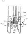
- frame assembly 10 comprises an outer boundary surface 21 of the frame assembly 10 forming profile 20, an inner boundary surface 41 of the frame assembly 10 forming profile 40, a total of 50 designated and two transparent discs 52 and 54, which are separated by a spacer 56 from each other, having a filling and a generally designated 60 holding means for holding the filling 50 to the frame assembly 10th
- the profiles 20 and 40 are executed in the embodiment of the invention shown in the drawing as extruded aluminum profiles and spaced apart in a direction perpendicular to the outer surface 21 and inner surface 41 extending direction.
- the profiles 20 and 40 are at the in Fig. 1 illustrated embodiment of the invention via a two connecting elements 80, 100 having connecting means connected to each other.
- the connecting element 80 arranged on the side of the connecting element 100 facing away from the filling 50 has an approximately perpendicular to the outer boundary surface 21 and parallel to the longitudinal axis of the profiles 20 and 40 extending central region, which increases in the direction of the filling 50 ramp areas 84 and 86th in thickened end portions 88 and 90 passes.
- the edge region 90 is received in a parallel to the longitudinal axis of the profile 20 extending lateral groove 30 of the profile 20.
- the thickened edge region 88 is received in a longitudinal groove 32 of the profile 40 which is open parallel to the longitudinal axis of the profile 40.
- the groove openings of the grooves 30 and 32 face each other.
- the filling walls 50 facing away from the groove walls 31 and 33 of the grooves 30 and 32 can be bent after insertion of the connecting element 80 in the direction of the filling 50 upwards.
- Overall, by receiving the thickened edge regions 88 and 90 in the grooves 30 and 32 of the profiles 20 and 40 ensures a positive connection between the profiles 20 and 40 via the connecting element 80.
- connection element 100 arranged on the side of the connecting element 80 facing the filling 50 is designed. It has a central region 101 which forms a boundary surface of the connecting element 100 facing the filling 50 and equipped with a coupling device 120. On both sides of the coupling device 120, the connecting element 100 drops over ramp areas 104 and 106 in the direction of thickened edge areas 108 and 110, respectively.
- the thickened edge regions 108 and 110 are received in grooves 22 and 42 of the profiles 20 and 40, respectively, which have mutually facing groove openings.
- the groove wall 24 of the groove 22 facing away from the connecting element 80 can be bent downwards in the direction of the connecting element 80 after insertion of the thickened edge region 110.
- the groove wall 44 facing away from the connecting element 80 can be bent down into the groove 42 after the thickened edge region 108 has been inserted so as to achieve a positive connection between the connecting element 100 and the edge profiles 20 and 40 arranged on both sides of the connecting element 100.
- the coupling device 120 arranged on the boundary surface 102 facing the filling 50 of the connecting element 100 is embodied in one piece with the connecting element 100 and has a bracket 124 extending approximately parallel to the boundary surface 102 of the connecting element facing the filling 50. Between the filling surface 50 facing away from the boundary surface of the bracket 124 and the filling 50 facing boundary surface 102 of the central region of the connecting element 100 is an open towards the inner profile 40 groove 122 is formed.
- the closed in the embodiment of the invention shown in the drawing groove bottom 126 of the groove 122 is the outer boundary surface 21 forming profile 20 faces.
- the groove 122 of the coupling device 120 serves to receive a retaining strip 62 of the holding device 60.
- the reception of the retaining strip 62 is promoted by the fact that the groove opening tapers in the direction of the groove bottom 126.
- the holding device 60 extends in the direction of the inner boundary surface 41 of the profile 40 approximately parallel to a coplanar to the filling 50 facing boundary surface 102 of the connecting element 100 extending support surface 46 of the profile 40. On its side facing away from the profile 20 If the bearing surface 46 in a in the direction of the filling 50 having the interior of the frame projecting retaining web 48 via.
- a groove open in the direction of the coupling groove 122 is formed, into which a retaining lug 64 of the holding device 60 can be clipped.
- the holding web 48 can be inserted into the coupling groove 122 and the holding device 60 can be pivoted overall in a direction away from the filling 50, whereby the retaining lug 64 is clipped into the retaining groove.
- the holding device 60 has on its side facing away from the holding web 48 an approximately parallel to the inner boundary surface 41 extending cover strip 66 which rests on the retaining lug 64 opposite side via two abutment protrusions 68 on the inner disc 54 of the filling 50. Due to the coplanar design of bearing surface 46 on the one hand and the filling 50 facing boundary surface 102 of the connecting device 100 on the other hand, the insertion of the holding device 60 is favored in the coupling groove 122.
- the outer boundary surface 21 forming profile 20 also has a preferably coplanar to the support surface 46 and the filling 50 facing boundary surface 28.
- the retaining web 70 serves to ensure a reliable positioning of the filling 50 with respect to the profile 20. He is a total, as well as the Connecting elements 80 and 100, made of a thermally insulating material, such as plastic. This further improves the thermal separation between the aluminum profiles 20 and 40.
- the profile 20 On the side facing away from the profile 40 of the boundary surface 28, the profile 20 is in a in the direction of the filling 50 receiving the interior of the frame extending sealing leg 27 over. This is provided on its outer disk 52 of the filling 50 facing side with a groove 26 in which a on the other hand on the outer disk 52 of the filling 50 fitting seal 29 is received.
- the inventively achievable thermal separation between the profiles 20 and 40 can also be achieved without affecting the overall stability of the arrangement, if this ratio in the range between 1: 4 and 1: 12, esp. 1: 6 and 1:10, is set.
- FIG. 2 is a sectional view of the in Fig. 1 shown frame assembly 10 in the region of a connecting rung 150 between two spaced parallel to each other extending frame assemblies 10 shown.
- a screw bolt 160 is screwed into the connecting rung 150.
- the bolt 160 passes through an opening 170 in the connecting element 80 and an opening 172 in the connecting element 100.
- the bolt head 162 is located on a connecting rung 150 facing away from the boundary surface of the support strips 25 and 45 at.
- the support strips 25 and 45 thus fulfill a dual function as a support web for the bolt head 162 of the bolt 160 and as a support strip for the support projections of the connecting element 100, as particularly clearly in Fig. 2 can be seen.
- connecting rungs 150 between individual frame assemblies 10 there is a metallic connection between the profiles 20 and 40 only in the area of usually also made of metal bolts 160.
- frame assemblies 10 is on the filling 50 and the connecting rung 150 facing away from a recess 200 formed, which serves in the production of sectional door panels for receiving a projection 68 at the upper edge of a arranged under the frame assembly 10 profile 20, 40.
- a Fingerklemmschutz can be effected. That is in detail in the EP 0 370 376 explained.
- the disclosure of this document is hereby incorporated by reference into this description with respect to the achievable by receiving projections in recesses finger protection effect and the shaping of projection and recess.
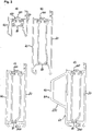
- FIG. 3 Frame assemblies 10 are shown which are provided to form a lower edge of a sectional door panel. All frame assemblies 10 have in common that they have two aluminum extrusions 20 and 40, which via connecting elements 80 and 100 are positively connected to each other, wherein in the region of the filling 50 (not shown) facing boundary surface 102 of the connecting element 100, a coupling device 120 for producing a positive connection with a designed to hold the filling 50 holding device 60 is arranged.
- FIG. 3a shown frame assembly corresponds to the frame assembly 10 according to the Fig. 1 and 2 ,
- the distance between the connecting elements 80 and 100 and the profile height of the profiles 20 and 40 are larger.
- the frame arrangements according to Fig. 3c) and 3d ) have at their lower edge a retaining groove 200 for receiving a bottom seal.
- a reinforcing element 220 is provided in the region of the inner boundary surface 41, which is placed on the boundary surface 41.
- Fig. 4a a frame arrangement is shown, which is intended to form an upper edge of Sedgingaltorpaneelen.
- FIG. 4 shown frame assemblies consisting essentially of two aluminum extruded profiles 20 and 40, of which the aluminum extruded profile 20 forms an outer boundary surface 21 of the frame assembly 10 and the aluminum extruded profile 40 an inner boundary surface 41 of the frame assembly 10.
- the profiles 20 and 40 according to Fig. 4 are, as well as the profiles (20, 40) according to Fig. 3 , via connecting elements 80 and 100 connected to each other, wherein the connecting element 80 on the filling 50 (not shown) opposite side of the connecting element 100 is disposed and on the filling 50 facing boundary surface 102 of the connecting element 100 has a coupling device 120 for producing a positive connection with associated with holding the filling 50 designed holding device 60.
- open projections 210 are formed, which can be inserted into corresponding recesses 200 in the region of the lower edge of the profiles 20 and 40 of adjacent Sekomaltorpaneele so as to bring about a desired Fingerklemmschutz für.
- the frame assemblies formed by the profiles 20 and 40 have an opening 250 which can be closed by means of a cover made of a suitable thermally insulating material, such as plastic.
- two, three or more frame assemblies 10 may be used in accordance with Fig. 1 to 4 be connected together so that they circulate a total of 50 filling.
- the frame is formed from only one frame assembly 10.
- a frame completely surrounding a filling 50 is first produced from the profiles 20 forming the outer boundary surface 21 and the profiles 40 and the connecting elements 80 and 100 forming the inner boundary surface 41. If necessary, a seal 29 and a spacer 56 are then inserted into the frame.
- the frame can be placed on the outer boundary surface 21.
- the filling 50 is then inserted into the frame prepared in this way.
- the holding device 60 is inserted into the coupling groove 122 until the projections 68 abut against the inner boundary surface 41 of the disk 54. Subsequently, the holding device 60 is pivoted in a direction away from the filling 50 until the retaining lug 64 clings into the retaining strip 62.
- the invention is not limited to the embodiments explained with reference to the drawing. Rather, it is also intended to the production of frame assemblies with only one connecting element. Furthermore, three, four or more connecting elements for producing inventive frame arrangements can be used. With appropriate design of the profiles can be dispensed with a spacer. Likewise, if necessary, can be dispensed with seals.
- the invention is not limited only in connection with sectional aluminum panels with anti-pinch measures. It can also be used on panels without such measures.
- the holding means for the filling is positively connected to a connecting element made of a thermally insulating material so as to prevent the direct metallic contact between the individual profiles of the frame assembly.
Description
Die Erfindung betrifft ein Sektionaltor nach dem Oberbegriff des Patentanspruchs 1.The invention relates to a sectional door according to the preamble of patent claim 1.
Sektionaltore werden zum Verschließen von Garagen- und Hallenöffnungen eingesetzt. Sie weisen ein längs einer Führungsschienenanordnung zwischen einer Öffnungsstellung und einer Schließstellung bewegbares Torblatt auf. Das Torblatt besteht aus einer Vielzahl von bzgl. senkrecht zur Bewegungsrichtung verlaufenden Gelenkachsen gegeneinander verschwenkbaren Sektionaltorpaneelen. Diese Torblattkonstruktion ermöglicht eine Öffnungs- und Schließbewegung längs der Führungsschienenanordnung ohne Ausschwenken des Torblatts in den dem damit zu verschließenden Raum abgewandten Bereich, weil die Torblattpaneele längs eines bogenförmigen Führungsschienenbereichs anliegen und gegeneinander verkippt werden können. Die Führungsschienen weisen regelmäßig einen ersten geradlinig und in Schwererichtung verlaufenden Führungsschienenabschnitt, einen zweiten geradlinig und im Wesentlichen in horizontaler Richtung verlaufenden Führungsschienenbereich und einen die beiden geradlinig verlaufenden Führungsschienenbereiche miteinander verbindenden gebogenen Führungsschienenbereich auf. Der horizontale Führungsschienenbereich ist dabei üblicherweise über Kopf angeordnet, so dass das Sektionaltorblatt in der Öffnungsstellung über Kopf etwa in einer horizontalen Ebene angeordnet werden kann, während es in der Schließstellung etwa in einer Vertikalebene angeordnet ist.Sectional doors are used to close garage and hall openings. They have a door leaf movable along a guide rail arrangement between an open position and a closed position. The door leaf consists of a plurality of respect. With respect to the direction of movement extending hinge axes against each other pivotable Sektionaltorpaneelen. This Torblattkonstruktion allows an opening and closing movement along the guide rail assembly without pivoting of the door leaf in the space thus to be closed off the area because the Torblattpaneele rest along an arcuate guide rail area and can be tilted against each other. The guide rails are regular a first guide rail section running rectilinearly and in the direction of gravity, a second guide rail section running in a straight line and substantially in the horizontal direction, and a curved guide rail section interconnecting the two linearly extending guide rail sections. The horizontal guide rail area is usually arranged overhead, so that the Sektionaltorblatt can be arranged in the open position above the head approximately in a horizontal plane, while it is arranged in the closed position approximately in a vertical plane.
Bei der Konstruktion von Sektionaltoren muss darauf geachtet werden, dass neben einem sicheren Öffnungsabschluss auch eine ausreichende Stabilität des Torblatts in der Öffnungsstellung gewährleistet ist. Darüber hinaus wird in vielen Fällen auch noch gefordert, dass durch das Torblatt eine thermische Trennung zwischen dem mit dem Torblatt zu verschließenden Raum und dem Außenraum bereitgestellt wird. Bekanntermaßen können die Paneele solcher Torblätter als sog. Sandwichkonstruktionen ausgeführt werden, bei denen zwischen zwei Metallschalen ein isolierender Schaumkern aufgenommen ist. Entsprechende Sektionaltorblattpaneele sind bspw. in der
Durch die vorstehend beschriebenen Sandwich-Paneele wird nicht nur ein guter Einbruchsschutz und eine zufriedenstellende thermische Trennung erreicht, sondern auch ein wirksamer Sichtschutz. In vielen Fällen ist es allerdings gewünscht, dass das Sektionaltorblatt in der Schließstellung auch die Funktion eines Fensters aufweist. Zu diesem Zweck werden in der
Bei diesen bekannten Rahmenanordnungen sind die einzelnen Rahmenprofile über zwei Kunststoffleisten, also Verbindungselemente aus einem thermisch isolierenden Material, miteinander verbunden. In einen solchen Rahmen kann eine bspw. zwei transparente Scheiben aufweisende Füllung (Thermopen-Füllung) eingesetzt werden. Diese Füllung liegt üblicherweise über eine Dichtungsanordnung an einem Positionierungssteg des äußeren Profils an und kann dort mit Hilfe einer die Füllung untergreifenden Halteeinrichtung arretiert werden. Dabei sind die einzelnen Rahmenprofile üblicherweise, ebenso wie die Halteeinrichtung, zum Erhalt einer zufriedenstellenden Gesamtstabilität aus einem metallischen Werkstoff hergestellt, insbes. als Aluminium-Strangpressprofile ausgeführt.In these known frame arrangements, the individual frame profiles are connected to one another via two plastic strips, that is to say connecting elements made of a thermally insulating material. In such a frame, for example, two transparent discs having filling (Thermopen filling) can be used. This filling is usually on a seal assembly on a positioning web of the outer profile and can be locked there with the help of a filling engaging under holding device. The individual frame profiles are common, as well as the Holding device, to obtain a satisfactory overall stability made of a metallic material, esp. Executed as aluminum extruded profiles.
In der
Beim Einsatz der vorstehend beschriebenen Rahmenanordnung zur Herstellung von Sektionaltorpaneelen hat es sich gezeigt, dass eine zufriedenstellende thermische Trennung zwischen dem mit dem Torblatt zu verschließenden Innenraum und dem Außenraum nicht erhalten wird.When using the above-described frame assembly for the production of sectional door panels, it has been found that a satisfactory thermal separation between the interior space to be closed with the door leaf and the exterior space is not obtained.
Demnach liegt der Erfindung die Aufgabe zugrunde, ein Sektionaltor mit verbesserter thermischer Trennung zwischen Innen- und Außenraum bereitzustellen.Accordingly, the invention has for its object to provide a sectional door with improved thermal separation between the interior and exterior.
Erfindungsgemäß wird diese Aufgabe durch die im kennzeichnenden Teil des Patentanspruchs 1 angegebene Weiterbildung der bekannten Sektionaltore gelöst.According to the invention this object is achieved by the specified in the characterizing part of claim 1 development of the known sectional doors.
Dabei geht die Erfindung auf die Erkenntnis zurück, dass die im Stand der Technik beobachteten Probleme im Wesentlichen auf die durch die Halteeinrichtung bereitgestellten Wärme- bzw. Kältebrücken zurückzuführen sind. Bei der erfindungsgemäßen Weiterbildung wird ein unmittelbarer Wärmeübergang zwischen dem äußeren und dem inneren Profil der Rahmenanordnung über die Halteeinrichtung verhindert, weil die Halteeinrichtung unter Vermeidung eines gleichzeitigen Kontakts mit beiden Profilen der Rahmenanordnung über die Kopplungseinrichtung an die Verbindungseinrichtung aus thermisch isolierendem Material gekoppelt werden kann. Dadurch wird mit erfindungsgemäßen Rahmenanordnungen eine zufriedenstellende thermische Trennung zwischen Außen- und Innenraum erreicht.The invention is based on the knowledge that the problems observed in the prior art are essentially due to the heat or cold bridges provided by the holding device. In the development of the invention, a direct heat transfer between the outer and the inner profile of the frame assembly is prevented via the holding device, because the holding device can be coupled by avoiding simultaneous contact with two profiles of the frame assembly on the coupling device to the connecting device of thermally insulating material. As a result, a satisfactory thermal separation between exterior and interior is achieved with frame arrangements according to the invention.
Konstruktiv hat es sich als besonders günstig erwiesen, wenn die Kopplungseinrichtung einstückig mit einem sich zwischen dem Innen- und dem Außenprofil erstreckenden und vorzugsweise sowohl am Innen- als auch am Außenprofil befestigten Verbindungselement der Verbindungseinrichtung gebildet ist. Das Verbindungselement kann zusammen mit der Kopplungseinrichtung insgesamt aus Kunststoff hergestellt sein, bspw. als Kunststoff-Strangpressprofil.Structurally, it has proved to be particularly advantageous if the coupling device integrally with a extending between the inner and the outer profile and preferably both on the inner and on the outer profile fastened connecting element of the connecting device is formed. The connecting element can be made entirely of plastic together with the coupling device, for example as a plastic extruded profile.
Bei einer besonders einfachen und daher besonders bevorzugten Ausführungsform der Erfindung weist die Kopplungseinrichtung eine zum Aufnehmen einer Halteleiste der Halteeinrichtung ausgelegte und sich in Längsrichtung der Profile erstreckende Kopplungsnut mit einem einem Profil, insbes. dem inneren Profil, zugewandten Nutboden und einer dem anderen Profil zugewandten Nutöffnung auf. Die sich vom Nutboden in Richtung auf die Nutöffnung erstreckende Tiefenrichtung der Nut verläuft daher etwa senkrecht zur Außen- bzw. Innenseite des Rahmens. Dabei kann eine Nutwand durch die der Füllung zugewandte Begrenzungsfläche des Verbindungselements gebildet sein. Wenn diese Nutwand mit einer daran angrenzenden Auflagefläche des der Nutöffnung zugewandten Profils, vorzugsweise des inneren Profils, fluchtet, insbes. etwa koplanar damit ausgeführt ist, wird das Einführen der Halteleiste der Halteeinrichtung in die Nut begünstigt.In a particularly simple and therefore particularly preferred embodiment of the invention, the coupling means for receiving a retaining strip of the holding device and extending in the longitudinal direction of the profile extending coupling with a profile, esp. The inner profile, facing groove bottom and the other profile facing slot opening on. The depth direction of the groove extending from the groove bottom in the direction of the groove opening therefore extends approximately perpendicular to the outside or inside of the frame. In this case, a groove wall may be formed by the filling surface facing the boundary surface of the connecting element. If this groove wall is flush with an adjoining support surface of the groove opening facing profile, preferably the inner profile, esp. Coplanar is designed so that the insertion of the retaining strip of the holding device is favored in the groove.
Das Einsetzen der Halteleiste in die Nut kann ohne Beeinträchtigung der Halteeigenschaften weiter erleichtert werden, wenn sich die Nut ausgehend von der Nutöffnung in Richtung auf den Nutboden in einer etwa senkrecht zu der durch die der Füllung zugewandte Begrenzungsfläche des Verbindungselements gebildeten Nutwand verlaufenden Richtung verjüngt. Dabei kann die Nutweite auch abschnittweise konstant bleiben, um so eine stabile Kopplung der Halteeinrichtung an dem Verbindungselement zu sichern.The insertion of the retaining strip in the groove can be further facilitated without affecting the holding properties, when the groove tapers, starting from the groove opening in the direction of the groove bottom in a direction approximately perpendicular to the groove wall formed by the filling facing boundary surface of the connecting element. In this case, the groove width can remain constant in sections, so as to secure a stable coupling of the holding device to the connecting element.
Wenn die Auflagefläche des der Nutöffnung zugewandten Profils einen sich in Längsrichtung des Profils erstreckenden und ausgehend von der Auflagefläche in Richtung auf den die Füllung aufweisenden Innenraum des Rahmens vorspringenden Haltesteg aufweist, kann die Halteleiste bei entsprechender Dimensionierung zwischen Haltesteg und Kopplungsnut eingeklemmt werden. Dabei hat es sich im Sinne einer besonders stabilen Arretierung der Halteleiste als günstig erwiesen, wenn zwischen Haltesteg und Auflagefläche eine in Richtung auf die Kopplungsnut offene Haltenut zur Aufnahme einer Haltenase auf der der Kopplungsnut abgewandten Seite der Halteeinrichtung bzw. Halteleiste gebildet ist.If the support surface of the groove opening facing profile has a extending in the longitudinal direction of the profile and starting from the support surface in the direction of the filling having interior of the frame projecting retaining web, the retaining strip can be clamped with appropriate dimensioning between retaining web and coupling groove. It has proven to be favorable in terms of a particularly stable locking of the retaining strip when between holding web and support surface is open in the direction of the coupling groove holding groove for receiving a retaining lug on the side facing away from the coupling groove of the holding device or retaining strip.
Im Sinne einer vereinfachten Fertigung hat es sich als günstig erwiesen, wenn das Verbindungselement formschlüssig mit mindestens einem Profil verbunden ist. Dazu ist ein sich in Längsrichtung eines Profils erstreckender Verbindungsrand des Verbindungselements verdickt ausgeführt und in einer Verbindungsnut des Profils aufgenommen. Zur Erhöhung der Gesamtstabilität der Anordnung unter Vermeidung übermäßigen Materialaufwands hat es sich als günstig erwiesen, wenn das Verbindungselement gekröpft ausgeführt ist. Als besonders günstig hat es sich erwiesen, wenn das Verbindungselement auf einander entgegengesetzten Seiten der Kopplungsnut jeweils in eine der Füllung abgewandte Richtung abfällt und in jeweils einen verdickten Verbindungsrand ausläuft. Durch diese gekröpfte Ausführung des Verbindungselements können Verwindungen und Verformungen der daraus hergestellten Rahmenanordnung verhindert werden.In terms of simplified manufacturing, it has proven to be advantageous if the connecting element is positively connected to at least one profile. For this purpose, a connecting edge of the connecting element extending in the longitudinal direction of a profile is thickened and received in a connecting groove of the profile. To increase the overall stability of the arrangement while avoiding excessive material costs, it has proved to be advantageous when the connecting element is designed cranked. It has proved to be particularly favorable when the connecting element on opposite sides of the coupling groove in each case falls away in a direction away from the filling and terminates in a respective thickened connecting edge. By this cranked design of the connecting element twisting and deformation of the frame assembly made therefrom can be prevented.
Die Stabilität der Befestigung der Halteeinrichtung an der Kopplungseinrichtung des Verbindungselements wird erfindungsgemäß weiter dadurch verbessert, dass das Verbindungselement im Bereich seiner der Kopplungseinrichtung abgewandten Begrenzungsfläche mindestens einen sich in eine der Füllung abgewandte Richtung erstreckenden und zum Abstützen auf einer Stützleiste eines Profils ausgelegten Stützvorsprung aufweist. Durch diese Abstützung kann eine Verformung des Verbindungselements unter der Last der Halteeinrichtung unter Vermeidung übermäßigen Materialaufwands und gleichzeitiger Verbesserung der thermischen Trennung zwischen den Profilen verhindert werden.The stability of the attachment of the holding device to the coupling device of the connecting element is further improved according to the invention that the connecting element in the region of its boundary surface facing away from the coupling device at least one extending in one of the filling direction extending and designed for supporting on a support bar of a profile supporting projection. By virtue of this support, deformation of the connecting element under the load of the holding device can be prevented while avoiding excessive material expenditure and at the same time improving the thermal separation between the profiles.
Im Sinne einer besonders stabilen Verbindung der einzelnen Profile der Rahmenanordnung hat es sich als günstig erwiesen, wenn die Verbindungseinrichtung mindestens ein weiteres, sich etwa parallel zu dem mit der Kopplungseinrichtung ausgestatteten Verbindungselement erstreckendes, vorzugsweise an seinen entgegengesetzten Rändern mit jeweils einem Profil verbundenes Verbindungselement aufweist. Ebenso wie das die Kopplungseinrichtung aufweisende Verbindungselement kann auch das weitere Verbindungselement im Sinne einer Erhöhung der Gesamtstabilität gekröpft ausgeführt sein, wobei es ausgehend von seinen jeweils in einer Haltenut aufgenommenen, vorzugsweise verdeckten Rändern in eine der Füllung abgewandte Richtung zu einem Mittelbereich abfallen kann.In terms of a particularly stable connection of the individual profiles of the frame assembly, it has proven to be favorable if the connecting device has at least one further, approximately parallel to the equipped with the coupling device connecting element, preferably connected at its opposite edges, each with a profile connecting element. As well as the coupling element having the connecting element, the further connecting element can be designed cranked in terms of increasing the overall stability, and it can fall off in a direction away from its each received in a holding groove, preferably hidden edges in a filling direction to a central region.
Eine im Bereich der Füllung angeordnete Verbindungs- bzw. Stabilisierungssprosse eines aus einer erfindungsgemäßen Rahmenanordnung hergestellten Rahmens wird üblicherweise mit geeigneten Befestigungsbolzen bzw. Schraubbolzen an der Rahmenanordnung befestigt. Dabei hat es sich im Sinne einer Erhöhung der Gesamtstabilität unter Vermeidung einer Beeinträchtigung der thermischen Trennung als besonders zweckmäßig erwiesen, wenn mindestens ein Profil einer erfindungsgemäßen Rahmenanordnung einen Auflagesteg mit einer zum Anlegen eines Bolzenkopfs daran ausgelegten, der Füllung abgewandten Anlagefläche aufweist. In diesem Fall werden die einzelnen Profile der Rahmenanordnung nicht nur über die Verbindungselemente, sondern auch noch über den Bolzenkopf des Befestigungsbolzens thermisch miteinander gekoppelt. Der Querschnitt eines entsprechenden Bolzenkopfs ist allerdings regelmäßig so gering ausgeführt, dass die Wärmeleitung über den Bolzenkopf vernachlässigbar ist und mit Blick auf die durch die Anlage des Bolzenkopfs an der Anlagefläche erreichte Stabilitätserhöhung ohne weiteres in Kauf genommen werden kann.A connection or stabilization rung of a frame produced from a frame arrangement according to the invention arranged in the region of the filling usually becomes attached to the frame assembly with suitable fastening bolts or bolts. It has proved to be particularly useful in terms of increasing the overall stability while avoiding impairment of the thermal separation, if at least one profile of a frame assembly according to the invention has a support web with an applied for applying a bolt head thereto, the filling facing away from contact surface. In this case, the individual profiles of the frame assembly are thermally coupled to one another not only via the connecting elements, but also via the bolt head of the fastening bolt. The cross-section of a corresponding bolt head is, however, regularly made so low that the heat conduction over the bolt head is negligible and can be readily accepted in view of the stability increase achieved by the installation of the bolt head on the contact surface.
Unter Vermeidung einer direkten Beaufschlagung der aus einem thermisch isolierenden Material, wie etwa Kunststoff, hergestellten Verbindungselemente kann eine sichere Festlegung der Füllung an der Rahmenanordnung erreicht werden, wenn mindestens ein Verbindungselement eine von dem Befestigungsbolzen durchsetzte Aufnehmung aufweist, wobei der Bolzenkopf weiterhin an der Anlagefläche des Auflagestegs des Profils anliegt. Der Auflagesteg kann zwischen den Verbindungselementen angeordnet sein.By avoiding direct loading of the connecting elements made of a thermally insulating material, such as plastic, a secure fixing of the filling to the frame assembly can be achieved if at least one connecting element has a recess penetrated by the fastening bolt, wherein the bolt head continues to rest against the contact surface of the frame Abutment web of the profile is applied. The support web can be arranged between the connecting elements.
Bei einer besonders bevorzugten Ausführungsform der Erfindung ist der Auflagesteg durch die Stützleiste gebildet, welche demnach eine Doppelfunktion hat, bei der eine der Füllung zugewandte Begrenzungsfläche der Stützleiste zum Abstützen des Stützvorsprungs eines Verbindungselements dient, während eine der Füllung abgewandte Begrenzungsfläche der Stützleiste als Anlagefläche für den Bolzenkopf dient.In a particularly preferred embodiment of the invention, the support web is formed by the support strip, which therefore has a dual function in which one of the filling facing boundary surface of the support strip for supporting the support projection of a connecting element, while a filling facing away from the boundary surface of the support strip as a contact surface for the Bolt head is used.
Herstellungstechnisch ist es bevorzugt, wenn mindestens ein Profil als Aluminium-Strangpressprofil mit integriertem Auflagesteg, Stützleiste und Verbindungsnuten ausgeführt ist.Manufacturing technology, it is preferred if at least one profile is designed as an aluminum extruded profile with integrated support web, support bar and connecting grooves.
Zum Erhalt einer ausreichenden Festigkeit der Gesamtanordnung hat es sich als zweckmäßig erwiesen, wenn mindestens ein Verbindungselement zumindest teilweise aus einem glasfaserverstärkten Kunststoff, wie etwa Polypropylen mit Glasfaserverstärkung, hergestellt ist. Mit besonderem Vorteil kann ein unter dem Handelsnamen "TECATHERM PP GF" vertriebener Kunststoff, bestehend aus Polypropylen mit Glasfaserverstärkung, zum
Einsatz kommen. Das Verbindungselement weist vorzugsweise eine Zugfestigkeit gemäß ISO 527 von mehr als 50 MPa, vorzugsweise 57 MPa oder mehr, auf. Das Zugmodul des zum Herstellen des Verbindungselements benutzten Kunststoffs gemäß ISO 527 kann mehr als 3000, insbes. 4000 MPa oder mehr, betragen. Dabei weist der Kunststoff zweckmäßigerweise eine Bruchdehnung von mehr als 2,5 %, insbes. 3 % oder mehr, auf. Die Schlagzähigkeit beträgt zweckmäßigerweise mehr als 15 kJ/m2, insbes. 18 kJ/m2 oder mehr.In order to obtain a sufficient strength of the overall arrangement, it has proven to be expedient if at least one connecting element is at least partially made of a glass fiber reinforced plastic, such as polypropylene with glass fiber reinforcement. With particular advantage, a under the trade name "TECATHERM PP GF "sold plastic, consisting of polypropylene with glass fiber reinforcement, for
Use come. The connecting element preferably has a tensile strength according to ISO 527 of more than 50 MPa, preferably 57 MPa or more. The tensile modulus of the plastic used to make the fastener according to ISO 527 may be more than 3000, in particular 4000 MPa or more. The plastic expediently has an elongation at break of more than 2.5%, in particular 3% or more. The impact strength is expediently more than 15 kJ / m 2 , in particular 18 kJ / m 2 or more.
Zum Erhalt einer ausreichenden thermischen Trennung beträgt die Wärmeleitfähigkeit des zum Herstellen des Verbindungselements benutzten Kunststoffs gemäß DIN 52612 vorzugsweise weniger als 0,35 W/m·K, insbes. etwa 0,25 W/m·K. Dabei kann der thermische Längenausdehnungskoeffizient in Längsrichtung 2,5 bis 3,8 x 10⁻⁵/K betragen. Die Schmelztemperatur gemäß ISO 3146 beträgt vorzugsweise mehr als 120°C, insbes. 160°C oder mehr. Zweckmäßigerweise beträgt die Wärmeformbeständigkeitstemperatur (1,8 MPa) gemäß DIN EN ISO 75 118°C oder mehr.In order to obtain a sufficient thermal separation, the thermal conductivity of the plastic used to produce the connecting element according to DIN 52612 is preferably less than 0.35 W / m · K, in particular about 0.25 W / m · K. The coefficient of thermal expansion in the longitudinal direction may be 2.5 to 3.8 × 10 -5 / K. The melting temperature according to ISO 3146 is preferably more than 120 ° C, esp. 160 ° C or more. Conveniently, the heat distortion temperature (1.8 MPa) according to DIN EN ISO 75 is 118 ° C or more.
Ein unter Verwendung einer erfindungsgemäßen Rahmenanordnung hergestellter Rahmen kann vier erfindungsgemäße Rahmenanordnungen umfassen, welche eine Füllung umlaufen. Ein daraus hergestelltes Sektionaltorpaneel kann mindestens einen Rahmen aufweisen.A frame made using a frame assembly according to the invention may comprise four frame assemblies according to the invention which circulate a filling. A sectional aluminous panel made therefrom may have at least one frame.
Ein entsprechendes Sektionaltor weist mindestens ein Sektionaltorblatt mit mindestens einem entsprechenden Sektionaltorpaneel und eine Führungsschienenanordnung zum Führen einer Torblattbewegung zwischen einer Schließstellung, in der es etwa in einer Vertikalebene angeordnet ist, und einer Öffnungsstellung, in der es über Kopf etwa in einer Horizontalebene angeordnet ist, auf. Nachstehend wird die Erfindung unter Bezugnahme auf die Zeichnung, auf die hinsichtlich aller erfindungswesentlichen und in der Beschreibung nicht weiter herausgestellten Einzelheiten ausdrücklich verwiesen wird, erläutert. In der Zeichnung zeigt:
- Fig. 1
- eine Rahmenanordnung für ein Sektionaltorpaneel mit einer darin eingesetzten Füllung und einer zum Arretieren der Füllung an der Rahmenanordnung ausgelegten Halteeinrichtung,
- Fig. 2
- die Rahmenanordnung gemäß
Fig. 1 mit einem darin eingesetzten Befestigungsbolzen zum Befestigen einer einen Rahmen stabilisierenden Sprosse, - Fig. 3
- zum Herstellen eines unteren Randes eines Sektionaltorpaneels ausgelegte Rahmenanordnungen und
- Fig. 4
- zum Herstellen eines oberen Randes eines Sektionaltorpaneels ausgelegte Rahmenanordnungen.
- Fig. 1
- a frame arrangement for a sectional door panel with a filling inserted therein and a holding device designed to lock the filling to the frame arrangement,
- Fig. 2
- the frame arrangement according to
Fig. 1 with a fixing bolt inserted therein for fixing a rung stabilizing a frame, - Fig. 3
- For arranging a lower edge of a Sektionaltorpannels designed frame arrangements and
- Fig. 4
- For arranging an upper edge of a Sektionaltorpaneels designed frame arrangements.
Die in
Die Profile 20 und 40 sind bei der in der Zeichnung dargestellten Ausführungsform der Erfindung als Aluminium-Strangpressprofile ausgeführt und in einer sich senkrecht zur Außenfläche 21 bzw. Innenfläche 41 verlaufenden Richtung voneinander beabstandet. Die Profile 20 und 40 sind bei der in
Die Nutöffnungen der Nuten 30 und 32 sind einander zugewandt. Die der Füllung 50 abgewandten Nutwände 31 und 33 der Nuten 30 bzw. 32 können nach Einsetzen des Verbindungselements 80 in Richtung auf die Füllung 50 nach oben abgebogen werden. Insgesamt wird durch Aufnahme der verdickten Randbereiche 88 und 90 in den Nuten 30 und 32 der Profile 20 und 40 eine formschlüssige Verbindung zwischen den Profilen 20 und 40 über das Verbindungselement 80 sichergestellt.The groove openings of the
In ähnlicher Weise ist das auf der der Füllung 50 zugewandten Seite des Verbindungselements 80 angeordnete Verbindungselement 100 gestaltet. Es weist einen zentralen Bereich 101 auf, der eine der Füllung 50 zugewandte und mit einer Kopplungseinrichtung 120 ausgestattete Begrenzungsfläche des Verbindungselements 100 bildet. Beidseits der Kopplungseinrichtung 120 fällt das Verbindungselement 100 über Rampenbereiche 104 bzw. 106 in Richtung auf verdickte Randbereiche 108 bzw. 110 ab. Die verdickten Randbereiche 108 bzw. 110 sind in Nuten 22 bzw. 42 der Profile 20 bzw. 40 aufgenommen, welche einander zugewandte Nutöffnungen aufweisen. Die dem Verbindungselement 80 abgewandte Nutwand 24 der Nut 22 kann nach Einsetzen des verdickten Randbereichs 110 in Richtung auf das Verbindungselement 80 nach unten abgebogen werden. Ebenso kann die dem Verbindungselement 80 abgewandte Nutwand 44 nach Einsatz des verdickten Randbereichs 108 in die Nut 42 nach unten abgebogen werden, um so eine formschlüssige Verbindung zwischen dem Verbindungselement 100 und den beidseits des Verbindungselements 100 angeordneten Randprofilen 20 und 40 zu erreichen.In a similar manner, the
Die auf der der Füllung 50 zugewandten Begrenzungsfläche 102 des Verbindungselements 100 angeordnete Kopplungseinrichtung 120 ist einstückig mit dem Verbindungselement 100 ausgeführt und weist einen sich etwa parallel zu der der Füllung 50 zugewandten Begrenzungsfläche 102 des Verbindungselements erstreckenden Bügel 124 auf. Zwischen der der Füllung 50 abgewandten Begrenzungsfläche des Bügels 124 und der der Füllung 50 zugewandten Begrenzungsfläche 102 des mittleren Bereichs des Verbindungselements 100 ist eine in Richtung auf das innere Profil 40 offene Nut 122 gebildet. Der bei der in der Zeichnung dargestellten Ausführungsform der Erfindung geschlossene Nutboden 126 der Nut 122 ist dem die äußere Begrenzungsfläche 21 bildenden Profil 20 zugewandt. Auf der der Füllung 50 abgewandten Begrenzungsfläche des Verbindungselements 100 sind zwei sich in Richtung auf das untere Verbindungselement 80 erstreckende und etwa parallel zur Längsachse der Profile 20 und 40 bzw. des Verbindungselements 100 verlaufende Stützvorsprünge 112 ausgeführt, mit denen sich das Verbindungselement 100 an Stützleisten 25 bzw. 45 der Profile 20 bzw. 40 abstützt. Dadurch wird eine stabile Positionierung des Verbindungselements 100 bezüglich den Profilen 20 und 40 erreicht.The
Die Nut 122 der Kopplungseinrichtung 120 dient zum Aufnehmen einer Halteleiste 62 der Halteeinrichtung 60. Die Aufnahme der Halteleiste 62 wird dadurch begünstigt, dass sich die Nutöffnung in Richtung auf den Nutboden 126 verjüngt. Ausgehend von der Halteleiste 62 erstreckt sich die Halteeinrichtung 60 in Richtung auf die innere Begrenzungsfläche 41 des Profils 40 etwa parallel zu einer koplanar zu der der Füllung 50 zugewandten Begrenzungsfläche 102 des Verbindungselements 100 verlaufenden Auflagefläche 46 des Profils 40. Auf ihrer dem Profil 20 abgewandten Seite geht die Auflagefläche 46 in eine sich in Richtung auf den die Füllung 50 aufweisenden Innenraum des Rahmens vorspringenden Haltesteg 48 über. Zwischen dem Haltesteg 48 und der Auflagefläche 46 ist ein in Richtung auf die Kopplungsnut 122 offene Nut gebildet, in die eine Haltenase 64 der Halteeinrichtung 60 eingeklipst werden kann. Durch Aufnahme des Haltestegs 48 in der Kopplungsnut 122 und der Haltenase 64 in der zwischen Auflagefläche 46 und Haltesteg 48 gebildeten Nut wird die Halteeinrichtung 60 formschlüssig an der Rahmenanordnung 10 befestigt.The
Nach formschlüssiger Verbindung der Profile 20 und 40 mit Hilfe der Verbindungselemente 80 und 100 kann der Haltesteg 48 in die Kopplungsnut 122 eingeführt und die Halteeinrichtung 60 insgesamt in eine der Füllung 50 abgewandte Richtung verschwenkt werden, wodurch die Haltenase 64 in die Haltenut eingeklipst wird.After positive connection of the
Die Halteeinrichtung 60 weist auf ihrer dem Haltesteg 48 abgewandten Seite eine sich etwa parallel zur inneren Begrenzungsfläche 41 erstreckende Abdeckleiste 66 auf, welche auf der der Haltenase 64 abgewandten Seite über zwei Anlagevorsprünge 68 an der inneren Scheibe 54 der Füllung 50 anliegt. Durch die koplanare Ausführung von Auflagefläche 46 einerseits und der Füllung 50 zugewandter Begrenzungsfläche 102 der Verbindungseinrichtung 100 andererseits wird das Einsetzen der Halteeinrichtung 60 in die Kopplungsnut 122 begünstigt.The holding
Das die äußere Begrenzungsfläche 21 bildende Profil 20 weist ebenfalls eine vorzugsweise etwa koplanar zur Auflagefläche 46 ausgeführte und der Füllung 50 zugewandte Begrenzungsfläche 28 auf. Auf dieser Begrenzungsfläche 28 liegt ein der Halteeinrichtung 60 zugeordneter Haltesteg 70 über zwei Auflagestege 72 auf, von denen einer auf der Begrenzungsfläche 28 und einer auf der der Nutöffnung der Kopplungsnut 122 abgewandten Seite des Bügels 124 der der Füllung 50 zugewandten Begrenzungsfläche 102 des Verbindungselements 100 aufliegt. Der Haltesteg 70 dient zur Sicherstellung einer zuverlässigen Positionierung der Füllung 50 bezüglich dem Profil 20. Er ist insgesamt, ebenso wie die
Verbindungselemente 80 und 100, aus einem thermisch isolierenden Material, wie etwa Kunststoff, ausgeführt. Dadurch wird die thermische Trennung zwischen den Aluminiumprofilen 20 und 40 weiter verbessert. Auf der dem Profil 40 abgewandten Seite der Begrenzungsfläche 28 geht das Profil 20 in einen sich in Richtung auf den die Füllung 50 aufnehmenden Innenraum des Rahmens erstreckenden Dichtschenkel 27 über. Dieser ist an seiner der äußeren Scheibe 52 der Füllung 50 zugewandten Seite mit einer Nut 26 versehen, in der eine andererseits an der äußeren Scheibe 52 der Füllung 50 anliegende Dichtung 29 aufgenommen ist.The
Durch die formschlüssige Verbindung der Profile 20 und 40 über die bei der in der Zeichnung dargestellten Ausführungsformen der Erfindung als Kunststoff-Strangpressprofile ausgeführten Verbindungselemente 80 und 100 wird eine thermische Trennung zu den Profilen 20 und 40 erreicht. Diese thermische Trennung wird auch nicht durch die zum Halten der Füllung 50 an der Rahmenanordnung 10 verwendete Halteeinrichtung 60 beeinträchtigt, weil die Halteeinrichtung 60 ausschließlich über das aus einem thermisch isolierenden Kunststoffmaterial ausgeführte Verbindungselement 100 mit dem Profil 20 verbunden ist, so dass ein direkter metallischer Kontakt zwischen äußerer Begrenzungsfläche 21 und innerer Begrenzungsfläche 41 trotz sicherer Positionierung der Füllung 50 bezüglich der Rahmenanordnung 10 vermieden ist.By the positive connection of the
Bei der in
In
172 in dem Verbindungselement 100. Der Schraubbolzenkopf 162 liegt an einer der Verbindungssprosse 150 abgewandten Begrenzungsfläche der Stützleisten 25 bzw. 45 an. Die Stützleisten 25 und 45 erfüllen demnach eine Doppelfunktion als Auflagesteg für den Schraubbolzenkopf 162 des Schraubbolzens 160 und als Stützleiste für die Stützvorsprünge des Verbindungselements 100, wie besonders deutlich in
172 in the connecting
Bei Verwendung von Verbindungssprossen 150 zwischen einzelnen Rahmenanordnungen 10 gibt es eine metallische Verbindung zwischen den Profilen 20 und 40 nur im Bereich der üblicherweise ebenfalls aus Metall ausgeführten Schraubbolzen 160. Die dadurch hervorgerufene Wärmeleitfähigkeit zwischen äußerer Begrenzungsfläche 21 und innerer Begrenzungsfläche 41 kann aber mit Blick auf die Verwendung matallischer Schraubbolzen, die sich auf entsprechenden Stützleisten 25 und 45 abstützen, in Kauf genommen werden.When using connecting
Bei den in den
In
Die in
Bei der Rahmenanordnung gemäß
Die Rahmenanordnungen gemäß den
Bei der in
In
Ebenso wie die in
Am oberen Rand der Rahmenanordnungen gemäß
Gemäß
Zum Herstellen eines Rahmens für ein Sektionaltorpaneel können zwei, drei oder mehr Rahmenanordnungen 10 gemäß den
Bei einer anderen Ausführungsform der Erfindung ist der Rahmen aus nur einer Rahmenanordnung 10 gebildet. Zum Herstellen eines erfindungsgemäßen Sektionaltorpaneels wird zunächst ein eine Füllung 50 vollständig umlaufender Rahmen aus den die äußere Begrenzungsfläche 21 bildenden Profilen 20 und den die innere Begrenzungsfläche 41 bildenden Profilen 40 und den Verbindungselementen 80 und 100 hergestellt. In den Rahmen werden dann ggf. eine Dichtung 29 und ein Abstandhalter 56 eingesetzt. Dazu kann der Rahmen auf die äußere Begrenzungsfläche 21 aufgelegt werden. In den so vorbereiteten Rahmen wird anschließend die Füllung 50 eingesetzt. Schließlich wird die Halteeinrichtung 60 in die Kopplungsnut 122 eingeführt, bis die Vorsprünge 68 an der inneren Begrenzungsfläche 41 der Scheibe 54 anliegen. Anschließend wird die Halteeinrichtung 60 in eine der Füllung 50 abgewandte Richtung verschwenkt, bis die Haltenase 64 in die Halteleiste 62 einklipst.In another embodiment of the invention, the frame is formed from only one
Die Erfindung ist nicht auf die anhand der Zeichnung erläuterten Ausführungsbeispiele beschränkt. Vielmehr ist auch an die Herstellung von Rahmenanordnungen mit nur einem Verbindungselement gedacht. Ferner können drei, vier oder mehr Verbindungselemente zur Herstellung erfindungsgemäßer Rahmenanordnungen zum Einsatz kommen. Bei entsprechender Gestaltung der Profile kann auf einen Abstandhalter verzichtet werden. Ebenso kann ggf. auch auf Dichtungen verzichtet werden.The invention is not limited to the embodiments explained with reference to the drawing. Rather, it is also intended to the production of frame assemblies with only one connecting element. Furthermore, three, four or more connecting elements for producing inventive frame arrangements can be used. With appropriate design of the profiles can be dispensed with a spacer. Likewise, if necessary, can be dispensed with seals.
Die Erfindung ist nicht nur im Zusammenhang mit Sektionaltorpaneelen mit Fingerklemmschutzmaßnahmen beschränkt. Sie kann auch bei Paneelen ohne solche Maßnahmen zum Einsatz kommen.The invention is not limited only in connection with sectional aluminum panels with anti-pinch measures. It can also be used on panels without such measures.
Im Rahmen dieser Beschreibung wurde die Erfindung anhand eines Sektionaltorpaneels mit einer Füllung aus transparenten Scheiben erläutert. Allerdings ist auch an den Einsatz der Erfindung mit Füllungen aus einem nicht undurchlässigen Material gedacht.In the context of this description, the invention has been explained with reference to a sectional aluminum panel with a filling of transparent panes. However, it is also intended to use the invention with fillings of a non-impermeable material.
Wesentlich ist im Rahmen der Erfindung, dass die Halteeinrichtung für die Füllung formschlüssig mit einem Verbindungselement aus einem thermisch isolierenden Material verbunden ist, um so den direkten metallischen Kontakt zwischen den einzelnen Profilen der Rahmenanordnung zu verhindern.It is essential in the context of the invention that the holding means for the filling is positively connected to a connecting element made of a thermally insulating material so as to prevent the direct metallic contact between the individual profiles of the frame assembly.
- 1010
- Rahmenanordnungframe assembly
- 20, 4020, 40
- Profile / Randprofile / Aluminiumprofile / Aluminium-StrangprofileProfiles / edge profiles / aluminum profiles / extruded aluminum profiles
- 2121
- äußere Begrenzungsflächeouter boundary surface
- 22, 4222, 42
- Nuten / VerbindungsnutenGrooves / connecting grooves
- 24, 4424, 44
- Nutwände (dem Verbindungselement abgewandt) / Außenseite d. RahmensGroove walls (facing away from the connecting element) / outside d. frame
- 25, 4525, 45
- Stützleisten / AuflagestegeSupport strips / support webs
- 2626
- Nutgroove
- 2727
- Dichtschenkelsealing leg
- 2828
- Begrenzungsflächeboundary surface
- 2929
- Dichtungpoetry
- 30, 3230, 32
- Nuten / offene Längsnuten / HaltenutenGrooves / open longitudinal grooves / retaining grooves
- 31, 3331, 33
- Nutwände (der Füllung abgewandt)Groove walls (facing away from the filling)
- 4141
- innere Begrenzungsfläche / Innenseite d. Rahmensinner boundary surface / inside d. frame
- 4646
- Auflageflächebearing surface
- 48, 7048, 70
- Haltestegholding web
- 5050
- Füllungfilling
- 52, 5452, 54
- transparente Scheibentransparent slices
- 5656
- Abstandhalterspacer
- 6060
- Halteeinrichtungholder
- 6262
- Halteleisteretaining strip
- 6464
- Haltenaseretaining nose
- 6666
- Abdeckleistecover strip
- 6868
- Vorsprünge / AnlagevorsprüngeProjections / abutments
- 7272
- Auflagestegesupporting webs
- 80, 10080, 100
- Verbindungselemente / VerbindungseinrichtungConnecting elements / connecting device
- 84, 8684, 86
- Rampenbereicheramp areas
- 88, 9088, 90
- verdickte Endbereiche / RandbereicheThickened end areas / border areas
- 101101
- zentraler Bereich d. Verbindungselementscentral area d. connecting element
- 102102
- Begrenzungsfläche (der Füllung zugewandt)Bounding surface (facing the filling)
- 104, 106104, 106
- Rampenbereicheramp areas
- 108, 110108, 110
- verdickte Randbereiche / VerbindungsränderThickened edge areas / connection edges
- 112112
- Stützvorsprüngesupporting projections
- 120120
- Kopplungseinrichtungcoupling device
- 122122
- Nut / KopplungsnutGroove / coupling groove
- 124124
- Bügelhanger
- 126126
- Nutbodengroove bottom
- 150150
- Verbindungssprosse / StabilisierungssprosseConnecting rung / stabilizing rung
- 160160
- Schraubbolzen / BefestigungsbolzenBolt / mounting bolt
- 162162
- Schraubbolzenkopf / BolzenkopfBolt head / bolt head
- 170, 172170, 172
- Öffnung / AusnehmungOpening / recess
- 200200
- Ausnehmung / HaltenutRecess / retaining groove
- 210210
- offene Vorsprüngeopen projections
- 220220
- Verstärkungselementreinforcing element
- 250250
- Öffnungopening
Claims (15)
- A sectional door comprising a door leaf that has a plurality of sectional door panels that can swivel with respect to one another relative to articulation axes running perpendicular to a direction of movement and a guide rail arrangement for guiding a door leaf movement between a closed position, in which it is positioned approximately in a vertical plane, and an open position, in which it is positioned overhead in a horizontal plane, at least one sectional door panel having an infill (50), a holding device (60) designed to hold the infill (50), a frame arrangement (10) for producing a frame for the sectional door panel running around the infill (50) and having an outer profile (20) that forms an outside (21) of the frame and an inner profile (40) that forms an inside (41) of the frame, the profiles (20, 40) being spaced apart from one another in a direction preferably extending perpendicular to the outside or the inside, and being connected to one another by a connection device (80, 100) formed at least partially of a thermally insulating material, the connection device (80, 100) having a connection element with at least one boundary surface (102) facing the infill (50), characterised in that there is disposed on the boundary surface (102) of the connection element (100) facing the infill (50) a coupling device (120) serving to produce a positive connection to the holding device (60) and formed integrally with the connection element (100) of the connection device (80) extending between the inner profile (40) and the outer profile (20), and that the connection element (100) has in the region of its boundary surface facing away from the coupling device (120) at least one supporting projection (112) extending in a direction facing away from the infill (50) and designed for supporting on a support strip (25, 45) of a profile (20, 40), the connection element dropping down on both sides of the coupling device (120) over ramp regions (104, 106) to thickened edge regions (108, 110), which thickened edge regions (108, 110) are received in grooves (22, 42) of the profiles (20, 40).
- The sectional door according to Claim 1, characterised in that the coupling device (120) has a coupling groove (122) designed for receiving a holding strip (62) of the holding device (60) and extending in the longitudinal direction of the profiles (20, 40) and comprising a groove bottom (126) facing a profile (20) and a groove opening facing the other profile (40).
- The sectional door according to Claim 2, characterised in that a groove wall (24) is formed by the boundary surface (102) of the connection element (100) facing the infill (50), which groove wall is preferably aligned with an adjacent bearing surface (46) of the profile (40) facing the groove opening, and is in particular made to be co-planar with the latter.
- The sectional door according to Claim 3, characterised in that the bearing surface (46) transitions into a holding bar (48) that extends in the longitudinal direction of the profile (40) and projects from the bearing surface (46) in the direction of the interior of the frame that features the infill (50).
- The sectional door according to Claim 4, characterised in that a holding groove open in the direction of the coupling groove (122) is formed between the holding bar (48) and the bearing surface (46) for receiving a holding lug (64) on the side of the holding strip (62) facing away from the coupling groove (122).
- The sectional door according to any of the preceding claims, characterised in that a connection edge (108, 110) of the connection element (100) extending in the longitudinal direction of a profile (20, 40) is made so as to thicken and is received in a connection groove (22, 42) of a profile (20, 40).
- The sectional door according to Claim 6, characterised in that the connection element (100) drops down on opposing sides of the coupling groove (122) respectively in a direction facing away from the infill (50) and respectively terminates in a thickened connection edge (108, 110).
- The sectional door according to any of the preceding claims, characterised in that the connection device (80, 100) has at least one additional connection element (80) extending approximately parallel to the connection element (100) equipped with the coupling device (120), preferably connected to a respective profile (20, 40) on its opposing edges.
- The sectional door according to Claim 8, characterised in that the additional connection element (80) drops down from its edges (88, 90) respectively received in a holding groove (30, 32) in a direction facing away from the infill (50) to a central region.
- The sectional door according to any of the preceding claims, characterised by a fastening bolt (160), in particular a threaded bolt, designed for fastening a stabilising rail (150) to the frame arrangement (10), characterised in that at least one profile (20, 40) has a bearing bar (25, 45) with a bearing surface (46) facing away from the stabilising rail (150), designed for placing a bolt head (162) on said bearing bear.
- The sectional door according to Claim 10, characterised in that at least one connection element (80, 100) has a recess (170, 172) through which the fastening bolt (160) passes.
- The sectional door according to Claim 10 or 11, characterised in that the bearing bar (25, 45) is disposed between the connection elements (80, 100).
- The sectional door according to any of Claims 10 to 12, characterised in that the bearing bar (25, 45) is formed by the support strip (25, 45).
- The sectional door according to any of the preceding claims, characterised in that at least one profile (20, 40) is made as an aluminium extruded profile with an integrated bearing bar (72), support strip (25, 45) and connection grooves (22, 42).
- The sectional door according to any of the preceding claims, characterised in that at least one connection element (80, 100) is formed at least partially from a fibre-reinforced plastic, in particular polypropylene with glass fibre reinforcement.
Priority Applications (1)
| Application Number | Priority Date | Filing Date | Title |
|---|---|---|---|
| PL13002491T PL2666948T3 (en) | 2012-05-21 | 2013-05-10 | Frame assembly for a panel for sectional doors |
Applications Claiming Priority (1)
| Application Number | Priority Date | Filing Date | Title |
|---|---|---|---|
| DE102012010028A DE102012010028A1 (en) | 2012-05-21 | 2012-05-21 | FRAME ARRANGEMENT FOR A SECTIONAL PANEL |
Publications (2)
| Publication Number | Publication Date |
|---|---|
| EP2666948A1 EP2666948A1 (en) | 2013-11-27 |
| EP2666948B1 true EP2666948B1 (en) | 2018-02-21 |
Family
ID=48430425
Family Applications (1)
| Application Number | Title | Priority Date | Filing Date |
|---|---|---|---|
| EP13002491.2A Active EP2666948B1 (en) | 2012-05-21 | 2013-05-10 | Frame assembly for a panel for sectional doors |
Country Status (3)
| Country | Link |
|---|---|
| EP (1) | EP2666948B1 (en) |
| DE (1) | DE102012010028A1 (en) |
| PL (1) | PL2666948T3 (en) |
Families Citing this family (7)
| Publication number | Priority date | Publication date | Assignee | Title |
|---|---|---|---|---|
| DE102019115718A1 (en) | 2019-06-11 | 2020-12-17 | Hörmann KG Brockhagen | Sectional door |
| EP4136303A1 (en) * | 2020-04-16 | 2023-02-22 | ASSA ABLOY Entrance Systems AB | Entrance system |
| EP4323618A1 (en) * | 2021-04-15 | 2024-02-21 | ASSA ABLOY Entrance Systems AB | Panel arrangement, door leaf and door system |
| DE102023113971A1 (en) | 2022-05-27 | 2023-11-30 | Alpha Deuren International Bv | Frame formation as part of a panel element for a sectional door leaf |
| DE102022113452A1 (en) * | 2022-05-27 | 2023-11-30 | Alpha Deuren International Bv | Composite moldings |
| DE102022113451A1 (en) | 2022-05-27 | 2023-11-30 | Alpha Deuren International Bv | Mounting strip |
| EP4283086A1 (en) | 2022-05-27 | 2023-11-29 | Alpha Deuren International BV | Frame construction as a panel element for a sectional door leaf |
Family Cites Families (8)
| Publication number | Priority date | Publication date | Assignee | Title |
|---|---|---|---|---|
| DE3343687A1 (en) * | 1983-11-30 | 1985-06-05 | Schweizerische Aluminium Ag, Chippis | METAL FRAME CONSTRUCTION FOR WINDOWS OR DOORS |
| ATE108859T1 (en) | 1988-11-25 | 1994-08-15 | Hoermann Kg | GATE LEAF. |
| DE19800130C1 (en) * | 1998-01-03 | 1999-05-20 | Hans Dieter Grotefeld | Connector for window or door frames |
| WO2002020930A1 (en) * | 2000-09-05 | 2002-03-14 | Crittall Windows Limited | Window frames |
| AT409999B (en) * | 2001-05-11 | 2002-12-27 | Bator Schweiz Ag | GOAL |
| GB0117104D0 (en) * | 2001-07-13 | 2001-09-05 | Sapa Building Systems Ltd | Window units |
| US7987633B2 (en) * | 2007-05-16 | 2011-08-02 | Alcoa Commercial Windows Llc | Construction product having a frame with multi-functional thermal break |
| FR2957965B1 (en) * | 2010-03-29 | 2012-05-11 | Trendel Et Fils A | INSULATED GARAGE DOOR |
-
2012
- 2012-05-21 DE DE102012010028A patent/DE102012010028A1/en active Pending
-
2013
- 2013-05-10 EP EP13002491.2A patent/EP2666948B1/en active Active
- 2013-05-10 PL PL13002491T patent/PL2666948T3/en unknown
Non-Patent Citations (1)
| Title |
|---|
| None * |
Also Published As
| Publication number | Publication date |
|---|---|
| DE102012010028A1 (en) | 2013-11-21 |
| PL2666948T3 (en) | 2018-07-31 |
| EP2666948A1 (en) | 2013-11-27 |
Similar Documents
| Publication | Publication Date | Title |
|---|---|---|
| EP2666948B1 (en) | Frame assembly for a panel for sectional doors | |
| EP3080375B2 (en) | Device for closing an opening in a building | |
| DE202005004338U1 (en) | Insulation strip for window or door frame profile has ridge profiles closing minor interface gaps | |
| DE19601505C1 (en) | Glass rim bracket | |
| EP1877640B1 (en) | Frame for a window or a door | |
| EP2472045B1 (en) | Window or blind frame for a window, door or similar | |
| EP1932997A2 (en) | Upper closure of a threshold, closure system and threshold | |
| DE102017100336A1 (en) | Door, window or facade element | |
| EP1683940A2 (en) | Window or door with adhesively fixed glazing panel | |
| WO2011067210A2 (en) | Sliding wall having at least two panels | |
| EP0730068B1 (en) | Skylight | |
| DE202004000817U1 (en) | Frame body made of a hollow, extruded plastic profile for windows and doors | |
| EP1057961A2 (en) | Threshold for housedoor and the housedoor | |
| EP3348731B1 (en) | Post and crossmember structure | |
| EP2610423A2 (en) | Lifting/sliding door | |
| EP0477544B1 (en) | Filling piece for glazing beads | |
| EP2072744B1 (en) | Architrave profile for a lifting sliding door | |
| DE10251431A1 (en) | Door for installation in door aperture in house has hinges connecting moving frame to fixed frame, with frame elements made of hollow profiles | |
| EP3770372B1 (en) | Box for holding a roller shutter or a sunshade and window or door | |
| DE102020103603B4 (en) | Flood-resistant sectional door | |
| DE202010013228U1 (en) | Support arrangement for a window, a door or the like. | |
| EP2055884B1 (en) | Support profile for composite profile for windows, doors or similar and composite profile with such a support profile | |
| EP3342971B1 (en) | Window or door with a sash with a glass substrate | |
| EP2206873A1 (en) | Heat insulated wall element unit for building facades | |
| DE10011576A1 (en) | Window or door frame for modular wall element for container, for dwelling or office; is inserted in slit in metal strip projecting from outer plate of wall element and secured by wedge seal in slit |
Legal Events
| Date | Code | Title | Description |
|---|---|---|---|
| PUAI | Public reference made under article 153(3) epc to a published international application that has entered the european phase |
Free format text: ORIGINAL CODE: 0009012 |
|
| 17P | Request for examination filed |
Effective date: 20130510 |
|
| AK | Designated contracting states |
Kind code of ref document: A1 Designated state(s): AL AT BE BG CH CY CZ DE DK EE ES FI FR GB GR HR HU IE IS IT LI LT LU LV MC MK MT NL NO PL PT RO RS SE SI SK SM TR |
|
| AX | Request for extension of the european patent |
Extension state: BA ME |
|
| 17Q | First examination report despatched |
Effective date: 20160520 |
|
| GRAP | Despatch of communication of intention to grant a patent |
Free format text: ORIGINAL CODE: EPIDOSNIGR1 |
|
| INTG | Intention to grant announced |
Effective date: 20171204 |
|
| GRAS | Grant fee paid |
Free format text: ORIGINAL CODE: EPIDOSNIGR3 |
|
| GRAA | (expected) grant |
Free format text: ORIGINAL CODE: 0009210 |
|
| AK | Designated contracting states |
Kind code of ref document: B1 Designated state(s): AL AT BE BG CH CY CZ DE DK EE ES FI FR GB GR HR HU IE IS IT LI LT LU LV MC MK MT NL NO PL PT RO RS SE SI SK SM TR |
|
| REG | Reference to a national code |
Ref country code: GB Ref legal event code: FG4D Free format text: NOT ENGLISH |
|
| REG | Reference to a national code |
Ref country code: CH Ref legal event code: EP |
|
| REG | Reference to a national code |
Ref country code: DE Ref legal event code: R096 Ref document number: 502013009425 Country of ref document: DE Ref country code: AT Ref legal event code: REF Ref document number: 971908 Country of ref document: AT Kind code of ref document: T Effective date: 20180315 |
|
| REG | Reference to a national code |
Ref country code: IE Ref legal event code: FG4D Free format text: LANGUAGE OF EP DOCUMENT: GERMAN |
|
| REG | Reference to a national code |
Ref country code: NL Ref legal event code: FP |
|
| REG | Reference to a national code |
Ref country code: SE Ref legal event code: TRGR |
|
| REG | Reference to a national code |
Ref country code: FR Ref legal event code: PLFP Year of fee payment: 6 |
|
| REG | Reference to a national code |
Ref country code: LT Ref legal event code: MG4D |
|
| PG25 | Lapsed in a contracting state [announced via postgrant information from national office to epo] |
Ref country code: ES Free format text: LAPSE BECAUSE OF FAILURE TO SUBMIT A TRANSLATION OF THE DESCRIPTION OR TO PAY THE FEE WITHIN THE PRESCRIBED TIME-LIMIT Effective date: 20180221 Ref country code: LT Free format text: LAPSE BECAUSE OF FAILURE TO SUBMIT A TRANSLATION OF THE DESCRIPTION OR TO PAY THE FEE WITHIN THE PRESCRIBED TIME-LIMIT Effective date: 20180221 Ref country code: CY Free format text: LAPSE BECAUSE OF FAILURE TO SUBMIT A TRANSLATION OF THE DESCRIPTION OR TO PAY THE FEE WITHIN THE PRESCRIBED TIME-LIMIT Effective date: 20180221 Ref country code: FI Free format text: LAPSE BECAUSE OF FAILURE TO SUBMIT A TRANSLATION OF THE DESCRIPTION OR TO PAY THE FEE WITHIN THE PRESCRIBED TIME-LIMIT Effective date: 20180221 Ref country code: NO Free format text: LAPSE BECAUSE OF FAILURE TO SUBMIT A TRANSLATION OF THE DESCRIPTION OR TO PAY THE FEE WITHIN THE PRESCRIBED TIME-LIMIT Effective date: 20180521 Ref country code: HR Free format text: LAPSE BECAUSE OF FAILURE TO SUBMIT A TRANSLATION OF THE DESCRIPTION OR TO PAY THE FEE WITHIN THE PRESCRIBED TIME-LIMIT Effective date: 20180221 |
|
| PG25 | Lapsed in a contracting state [announced via postgrant information from national office to epo] |
Ref country code: LV Free format text: LAPSE BECAUSE OF FAILURE TO SUBMIT A TRANSLATION OF THE DESCRIPTION OR TO PAY THE FEE WITHIN THE PRESCRIBED TIME-LIMIT Effective date: 20180221 Ref country code: RS Free format text: LAPSE BECAUSE OF FAILURE TO SUBMIT A TRANSLATION OF THE DESCRIPTION OR TO PAY THE FEE WITHIN THE PRESCRIBED TIME-LIMIT Effective date: 20180221 Ref country code: BG Free format text: LAPSE BECAUSE OF FAILURE TO SUBMIT A TRANSLATION OF THE DESCRIPTION OR TO PAY THE FEE WITHIN THE PRESCRIBED TIME-LIMIT Effective date: 20180521 Ref country code: GR Free format text: LAPSE BECAUSE OF FAILURE TO SUBMIT A TRANSLATION OF THE DESCRIPTION OR TO PAY THE FEE WITHIN THE PRESCRIBED TIME-LIMIT Effective date: 20180522 |
|
| PG25 | Lapsed in a contracting state [announced via postgrant information from national office to epo] |
Ref country code: MT Free format text: LAPSE BECAUSE OF FAILURE TO SUBMIT A TRANSLATION OF THE DESCRIPTION OR TO PAY THE FEE WITHIN THE PRESCRIBED TIME-LIMIT Effective date: 20180221 |
|
| PG25 | Lapsed in a contracting state [announced via postgrant information from national office to epo] |
Ref country code: RO Free format text: LAPSE BECAUSE OF FAILURE TO SUBMIT A TRANSLATION OF THE DESCRIPTION OR TO PAY THE FEE WITHIN THE PRESCRIBED TIME-LIMIT Effective date: 20180221 Ref country code: EE Free format text: LAPSE BECAUSE OF FAILURE TO SUBMIT A TRANSLATION OF THE DESCRIPTION OR TO PAY THE FEE WITHIN THE PRESCRIBED TIME-LIMIT Effective date: 20180221 Ref country code: AL Free format text: LAPSE BECAUSE OF FAILURE TO SUBMIT A TRANSLATION OF THE DESCRIPTION OR TO PAY THE FEE WITHIN THE PRESCRIBED TIME-LIMIT Effective date: 20180221 |
|
| REG | Reference to a national code |
Ref country code: DE Ref legal event code: R097 Ref document number: 502013009425 Country of ref document: DE |
|
| PG25 | Lapsed in a contracting state [announced via postgrant information from national office to epo] |
Ref country code: SM Free format text: LAPSE BECAUSE OF FAILURE TO SUBMIT A TRANSLATION OF THE DESCRIPTION OR TO PAY THE FEE WITHIN THE PRESCRIBED TIME-LIMIT Effective date: 20180221 Ref country code: DK Free format text: LAPSE BECAUSE OF FAILURE TO SUBMIT A TRANSLATION OF THE DESCRIPTION OR TO PAY THE FEE WITHIN THE PRESCRIBED TIME-LIMIT Effective date: 20180221 Ref country code: SK Free format text: LAPSE BECAUSE OF FAILURE TO SUBMIT A TRANSLATION OF THE DESCRIPTION OR TO PAY THE FEE WITHIN THE PRESCRIBED TIME-LIMIT Effective date: 20180221 |
|
| REG | Reference to a national code |
Ref country code: CH Ref legal event code: PL |
|
| PLBE | No opposition filed within time limit |
Free format text: ORIGINAL CODE: 0009261 |
|
| STAA | Information on the status of an ep patent application or granted ep patent |
Free format text: STATUS: NO OPPOSITION FILED WITHIN TIME LIMIT |
|
| 26N | No opposition filed |
Effective date: 20181122 |
|
| GBPC | Gb: european patent ceased through non-payment of renewal fee |
Effective date: 20180521 |
|
| REG | Reference to a national code |
Ref country code: BE Ref legal event code: MM Effective date: 20180531 |
|
| PG25 | Lapsed in a contracting state [announced via postgrant information from national office to epo] |
Ref country code: MC Free format text: LAPSE BECAUSE OF FAILURE TO SUBMIT A TRANSLATION OF THE DESCRIPTION OR TO PAY THE FEE WITHIN THE PRESCRIBED TIME-LIMIT Effective date: 20180221 |
|
| REG | Reference to a national code |
Ref country code: IE Ref legal event code: MM4A |
|
| PG25 | Lapsed in a contracting state [announced via postgrant information from national office to epo] |
Ref country code: SI Free format text: LAPSE BECAUSE OF FAILURE TO SUBMIT A TRANSLATION OF THE DESCRIPTION OR TO PAY THE FEE WITHIN THE PRESCRIBED TIME-LIMIT Effective date: 20180221 Ref country code: LI Free format text: LAPSE BECAUSE OF NON-PAYMENT OF DUE FEES Effective date: 20180531 Ref country code: CH Free format text: LAPSE BECAUSE OF NON-PAYMENT OF DUE FEES Effective date: 20180531 |
|
| PG25 | Lapsed in a contracting state [announced via postgrant information from national office to epo] |
Ref country code: LU Free format text: LAPSE BECAUSE OF NON-PAYMENT OF DUE FEES Effective date: 20180510 |
|
| PG25 | Lapsed in a contracting state [announced via postgrant information from national office to epo] |
Ref country code: IE Free format text: LAPSE BECAUSE OF NON-PAYMENT OF DUE FEES Effective date: 20180510 Ref country code: GB Free format text: LAPSE BECAUSE OF NON-PAYMENT OF DUE FEES Effective date: 20180521 |
|
| PG25 | Lapsed in a contracting state [announced via postgrant information from national office to epo] |
Ref country code: BE Free format text: LAPSE BECAUSE OF NON-PAYMENT OF DUE FEES Effective date: 20180531 |
|
| REG | Reference to a national code |
Ref country code: AT Ref legal event code: MM01 Ref document number: 971908 Country of ref document: AT Kind code of ref document: T Effective date: 20180510 |
|
| PG25 | Lapsed in a contracting state [announced via postgrant information from national office to epo] |
Ref country code: AT Free format text: LAPSE BECAUSE OF NON-PAYMENT OF DUE FEES Effective date: 20180510 |
|
| PG25 | Lapsed in a contracting state [announced via postgrant information from national office to epo] |
Ref country code: TR Free format text: LAPSE BECAUSE OF FAILURE TO SUBMIT A TRANSLATION OF THE DESCRIPTION OR TO PAY THE FEE WITHIN THE PRESCRIBED TIME-LIMIT Effective date: 20180221 |
|
| PG25 | Lapsed in a contracting state [announced via postgrant information from national office to epo] |
Ref country code: HU Free format text: LAPSE BECAUSE OF FAILURE TO SUBMIT A TRANSLATION OF THE DESCRIPTION OR TO PAY THE FEE WITHIN THE PRESCRIBED TIME-LIMIT; INVALID AB INITIO Effective date: 20130510 Ref country code: PT Free format text: LAPSE BECAUSE OF FAILURE TO SUBMIT A TRANSLATION OF THE DESCRIPTION OR TO PAY THE FEE WITHIN THE PRESCRIBED TIME-LIMIT Effective date: 20180221 |
|
| PG25 | Lapsed in a contracting state [announced via postgrant information from national office to epo] |
Ref country code: MK Free format text: LAPSE BECAUSE OF NON-PAYMENT OF DUE FEES Effective date: 20180221 |
|
| PG25 | Lapsed in a contracting state [announced via postgrant information from national office to epo] |
Ref country code: IS Free format text: LAPSE BECAUSE OF FAILURE TO SUBMIT A TRANSLATION OF THE DESCRIPTION OR TO PAY THE FEE WITHIN THE PRESCRIBED TIME-LIMIT Effective date: 20180621 |
|
| PGFP | Annual fee paid to national office [announced via postgrant information from national office to epo] |
Ref country code: FR Payment date: 20210521 Year of fee payment: 9 |
|
| PG25 | Lapsed in a contracting state [announced via postgrant information from national office to epo] |
Ref country code: FR Free format text: LAPSE BECAUSE OF NON-PAYMENT OF DUE FEES Effective date: 20220531 |
|
| PGFP | Annual fee paid to national office [announced via postgrant information from national office to epo] |
Ref country code: SE Payment date: 20230315 Year of fee payment: 11 |
|
| PGFP | Annual fee paid to national office [announced via postgrant information from national office to epo] |
Ref country code: NL Payment date: 20230519 Year of fee payment: 11 Ref country code: IT Payment date: 20230531 Year of fee payment: 11 Ref country code: DE Payment date: 20230519 Year of fee payment: 11 Ref country code: CZ Payment date: 20230428 Year of fee payment: 11 |
|
| PGFP | Annual fee paid to national office [announced via postgrant information from national office to epo] |
Ref country code: PL Payment date: 20230504 Year of fee payment: 11 |