EP0732142A2 - ContrÔle de la quantité de gaz dissous dans un liquide - Google Patents
ContrÔle de la quantité de gaz dissous dans un liquide Download PDFInfo
- Publication number
- EP0732142A2 EP0732142A2 EP96103808A EP96103808A EP0732142A2 EP 0732142 A2 EP0732142 A2 EP 0732142A2 EP 96103808 A EP96103808 A EP 96103808A EP 96103808 A EP96103808 A EP 96103808A EP 0732142 A2 EP0732142 A2 EP 0732142A2
- Authority
- EP
- European Patent Office
- Prior art keywords
- carbon dioxide
- module
- beer
- pressure
- liquid
- Prior art date
- Legal status (The legal status is an assumption and is not a legal conclusion. Google has not performed a legal analysis and makes no representation as to the accuracy of the status listed.)
- Withdrawn
Links
Images


Classifications
-
- B—PERFORMING OPERATIONS; TRANSPORTING
- B67—OPENING, CLOSING OR CLEANING BOTTLES, JARS OR SIMILAR CONTAINERS; LIQUID HANDLING
- B67D—DISPENSING, DELIVERING OR TRANSFERRING LIQUIDS, NOT OTHERWISE PROVIDED FOR
- B67D1/00—Apparatus or devices for dispensing beverages on draught
- B67D1/0042—Details of specific parts of the dispensers
- B67D1/0057—Carbonators
- B67D1/0069—Details
- B67D1/0077—Carbonator being specially adapted for adding a second gas to the CO2
-
- B—PERFORMING OPERATIONS; TRANSPORTING
- B01—PHYSICAL OR CHEMICAL PROCESSES OR APPARATUS IN GENERAL
- B01D—SEPARATION
- B01D19/00—Degasification of liquids
- B01D19/0031—Degasification of liquids by filtration
-
- B—PERFORMING OPERATIONS; TRANSPORTING
- B01—PHYSICAL OR CHEMICAL PROCESSES OR APPARATUS IN GENERAL
- B01D—SEPARATION
- B01D61/00—Processes of separation using semi-permeable membranes, e.g. dialysis, osmosis or ultrafiltration; Apparatus, accessories or auxiliary operations specially adapted therefor
-
- B—PERFORMING OPERATIONS; TRANSPORTING
- B01—PHYSICAL OR CHEMICAL PROCESSES OR APPARATUS IN GENERAL
- B01D—SEPARATION
- B01D63/00—Apparatus in general for separation processes using semi-permeable membranes
- B01D63/02—Hollow fibre modules
- B01D63/031—Two or more types of hollow fibres within one bundle or within one potting or tube-sheet
-
- B—PERFORMING OPERATIONS; TRANSPORTING
- B01—PHYSICAL OR CHEMICAL PROCESSES OR APPARATUS IN GENERAL
- B01F—MIXING, e.g. DISSOLVING, EMULSIFYING OR DISPERSING
- B01F23/00—Mixing according to the phases to be mixed, e.g. dispersing or emulsifying
- B01F23/20—Mixing gases with liquids
- B01F23/23—Mixing gases with liquids by introducing gases into liquid media, e.g. for producing aerated liquids
- B01F23/231—Mixing gases with liquids by introducing gases into liquid media, e.g. for producing aerated liquids by bubbling
- B01F23/23105—Arrangement or manipulation of the gas bubbling devices
- B01F23/2312—Diffusers
- B01F23/23124—Diffusers consisting of flexible porous or perforated material, e.g. fabric
-
- B—PERFORMING OPERATIONS; TRANSPORTING
- B01—PHYSICAL OR CHEMICAL PROCESSES OR APPARATUS IN GENERAL
- B01F—MIXING, e.g. DISSOLVING, EMULSIFYING OR DISPERSING
- B01F23/00—Mixing according to the phases to be mixed, e.g. dispersing or emulsifying
- B01F23/20—Mixing gases with liquids
- B01F23/23—Mixing gases with liquids by introducing gases into liquid media, e.g. for producing aerated liquids
- B01F23/236—Mixing gases with liquids by introducing gases into liquid media, e.g. for producing aerated liquids specially adapted for aerating or carbonating beverages
- B01F23/2362—Mixing gases with liquids by introducing gases into liquid media, e.g. for producing aerated liquids specially adapted for aerating or carbonating beverages for aerating or carbonating within receptacles or tanks, e.g. distribution machines
-
- B—PERFORMING OPERATIONS; TRANSPORTING
- B01—PHYSICAL OR CHEMICAL PROCESSES OR APPARATUS IN GENERAL
- B01F—MIXING, e.g. DISSOLVING, EMULSIFYING OR DISPERSING
- B01F23/00—Mixing according to the phases to be mixed, e.g. dispersing or emulsifying
- B01F23/20—Mixing gases with liquids
- B01F23/23—Mixing gases with liquids by introducing gases into liquid media, e.g. for producing aerated liquids
- B01F23/237—Mixing gases with liquids by introducing gases into liquid media, e.g. for producing aerated liquids characterised by the physical or chemical properties of gases or vapours introduced in the liquid media
- B01F23/2376—Mixing gases with liquids by introducing gases into liquid media, e.g. for producing aerated liquids characterised by the physical or chemical properties of gases or vapours introduced in the liquid media characterised by the gas being introduced
- B01F23/23762—Carbon dioxide
-
- B—PERFORMING OPERATIONS; TRANSPORTING
- B01—PHYSICAL OR CHEMICAL PROCESSES OR APPARATUS IN GENERAL
- B01F—MIXING, e.g. DISSOLVING, EMULSIFYING OR DISPERSING
- B01F23/00—Mixing according to the phases to be mixed, e.g. dispersing or emulsifying
- B01F23/20—Mixing gases with liquids
- B01F23/23—Mixing gases with liquids by introducing gases into liquid media, e.g. for producing aerated liquids
- B01F23/237—Mixing gases with liquids by introducing gases into liquid media, e.g. for producing aerated liquids characterised by the physical or chemical properties of gases or vapours introduced in the liquid media
- B01F23/2376—Mixing gases with liquids by introducing gases into liquid media, e.g. for producing aerated liquids characterised by the physical or chemical properties of gases or vapours introduced in the liquid media characterised by the gas being introduced
- B01F23/23765—Nitrogen
-
- B—PERFORMING OPERATIONS; TRANSPORTING
- B67—OPENING, CLOSING OR CLEANING BOTTLES, JARS OR SIMILAR CONTAINERS; LIQUID HANDLING
- B67D—DISPENSING, DELIVERING OR TRANSFERRING LIQUIDS, NOT OTHERWISE PROVIDED FOR
- B67D1/00—Apparatus or devices for dispensing beverages on draught
- B67D1/0042—Details of specific parts of the dispensers
- B67D1/0057—Carbonators
- B67D1/0061—Carbonators with cooling means
- B67D1/0066—Carbonators with cooling means outside the carbonator
- B67D1/0068—Cooling bath
-
- B—PERFORMING OPERATIONS; TRANSPORTING
- B67—OPENING, CLOSING OR CLEANING BOTTLES, JARS OR SIMILAR CONTAINERS; LIQUID HANDLING
- B67D—DISPENSING, DELIVERING OR TRANSFERRING LIQUIDS, NOT OTHERWISE PROVIDED FOR
- B67D1/00—Apparatus or devices for dispensing beverages on draught
- B67D1/0042—Details of specific parts of the dispensers
- B67D1/0057—Carbonators
- B67D1/0069—Details
- B67D1/0071—Carbonating by injecting CO2 in the liquid
- B67D1/0072—Carbonating by injecting CO2 in the liquid through a diffuser, a bubbler
-
- B—PERFORMING OPERATIONS; TRANSPORTING
- B67—OPENING, CLOSING OR CLEANING BOTTLES, JARS OR SIMILAR CONTAINERS; LIQUID HANDLING
- B67D—DISPENSING, DELIVERING OR TRANSFERRING LIQUIDS, NOT OTHERWISE PROVIDED FOR
- B67D1/00—Apparatus or devices for dispensing beverages on draught
- B67D1/0042—Details of specific parts of the dispensers
- B67D1/0057—Carbonators
- B67D1/0069—Details
- B67D1/0074—Automatic carbonation control
- B67D1/0075—Automatic carbonation control by sensing gas pressure
-
- B—PERFORMING OPERATIONS; TRANSPORTING
- B67—OPENING, CLOSING OR CLEANING BOTTLES, JARS OR SIMILAR CONTAINERS; LIQUID HANDLING
- B67D—DISPENSING, DELIVERING OR TRANSFERRING LIQUIDS, NOT OTHERWISE PROVIDED FOR
- B67D1/00—Apparatus or devices for dispensing beverages on draught
- B67D1/04—Apparatus utilising compressed air or other gas acting directly or indirectly on beverages in storage containers
-
- B—PERFORMING OPERATIONS; TRANSPORTING
- B67—OPENING, CLOSING OR CLEANING BOTTLES, JARS OR SIMILAR CONTAINERS; LIQUID HANDLING
- B67D—DISPENSING, DELIVERING OR TRANSFERRING LIQUIDS, NOT OTHERWISE PROVIDED FOR
- B67D1/00—Apparatus or devices for dispensing beverages on draught
- B67D1/08—Details
- B67D1/12—Flow or pressure control devices or systems, e.g. valves, gas pressure control, level control in storage containers
- B67D1/1252—Gas pressure control means, e.g. for maintaining proper carbonation
-
- B—PERFORMING OPERATIONS; TRANSPORTING
- B01—PHYSICAL OR CHEMICAL PROCESSES OR APPARATUS IN GENERAL
- B01D—SEPARATION
- B01D2313/00—Details relating to membrane modules or apparatus
- B01D2313/90—Additional auxiliary systems integrated with the module or apparatus
- B01D2313/903—Integrated control or detection device
-
- B—PERFORMING OPERATIONS; TRANSPORTING
- B01—PHYSICAL OR CHEMICAL PROCESSES OR APPARATUS IN GENERAL
- B01F—MIXING, e.g. DISSOLVING, EMULSIFYING OR DISPERSING
- B01F23/00—Mixing according to the phases to be mixed, e.g. dispersing or emulsifying
- B01F23/20—Mixing gases with liquids
- B01F23/23—Mixing gases with liquids by introducing gases into liquid media, e.g. for producing aerated liquids
- B01F23/231—Mixing gases with liquids by introducing gases into liquid media, e.g. for producing aerated liquids by bubbling
- B01F23/23105—Arrangement or manipulation of the gas bubbling devices
- B01F23/2312—Diffusers
- B01F23/23124—Diffusers consisting of flexible porous or perforated material, e.g. fabric
- B01F23/231244—Dissolving, hollow fiber membranes
-
- B—PERFORMING OPERATIONS; TRANSPORTING
- B67—OPENING, CLOSING OR CLEANING BOTTLES, JARS OR SIMILAR CONTAINERS; LIQUID HANDLING
- B67D—DISPENSING, DELIVERING OR TRANSFERRING LIQUIDS, NOT OTHERWISE PROVIDED FOR
- B67D1/00—Apparatus or devices for dispensing beverages on draught
- B67D1/04—Apparatus utilising compressed air or other gas acting directly or indirectly on beverages in storage containers
- B67D2001/0475—Type of gas or gas mixture used, other than pure CO2
- B67D2001/0487—Mixture of gases, e.g. N2 + CO2
-
- B—PERFORMING OPERATIONS; TRANSPORTING
- B67—OPENING, CLOSING OR CLEANING BOTTLES, JARS OR SIMILAR CONTAINERS; LIQUID HANDLING
- B67D—DISPENSING, DELIVERING OR TRANSFERRING LIQUIDS, NOT OTHERWISE PROVIDED FOR
- B67D1/00—Apparatus or devices for dispensing beverages on draught
- B67D1/08—Details
- B67D1/12—Flow or pressure control devices or systems, e.g. valves, gas pressure control, level control in storage containers
- B67D1/1252—Gas pressure control means, e.g. for maintaining proper carbonation
- B67D2001/1254—Gas pressure control means, e.g. for maintaining proper carbonation comprising means for making a mixture of gases
-
- Y—GENERAL TAGGING OF NEW TECHNOLOGICAL DEVELOPMENTS; GENERAL TAGGING OF CROSS-SECTIONAL TECHNOLOGIES SPANNING OVER SEVERAL SECTIONS OF THE IPC; TECHNICAL SUBJECTS COVERED BY FORMER USPC CROSS-REFERENCE ART COLLECTIONS [XRACs] AND DIGESTS
- Y10—TECHNICAL SUBJECTS COVERED BY FORMER USPC
- Y10S—TECHNICAL SUBJECTS COVERED BY FORMER USPC CROSS-REFERENCE ART COLLECTIONS [XRACs] AND DIGESTS
- Y10S261/00—Gas and liquid contact apparatus
- Y10S261/07—Carbonators
Definitions
- the present invention relates to the control of dissolved gases in liquids including beverages and particularly beer.
- the most common gases to be controlled are carbon dioxide and nitrogen.
- the raising or lowering of a concentration of a gas takes place in a contactor module containing hollow fiber membranes wherein the beer flows through the shell side of the module and gas is controlled by partial pressure regulation in the bores of the hollow fibers.
- the carbonation level is about 2.5 volumes of carbon dioxide per volume of liquid, and for the dark stout beers that level is about 1.0.
- Many customers, particularly in Europe express a preference for a tight long-lasting head on dispensed beer.
- the desired presentation of a tight long lasting head cannot be achieved with only carbon dioxide in solution. This is true because carbon dioxide is able to permeate rapidly through the thin walls of the initially formed bubbles on the surface of a dispensed beer and hence is lost to the atmosphere which contains a low concentration of carbon dioxide.
- these initially formed nitrogen bubbles are very small, they float slowly to the surface of the beer and some nucleate precipitation of dissolved carbon dioxide gas which enters them, causing them to grow and float faster.
- the small bubbles which collect at the surface thus contain nitrogen and a mixture of carbon dioxide and nitrogen gases. Because nitrogen, in comparison to carbon dioxide, is less able to permeate through the bubble wall, these bubbles are relatively stable, although they are losing carbon dioxide by permeation to the atmosphere. That loss tends to be made up by further carbon dioxide arising from the bulk of the beer in the glass. Hence the "head" on a nitrogenated beer lasts longer and is more appealing to most customers.
- U.S. Patent 5,062,548 attempts to introduce nitrogen into the beer during the dispense operation via a restrictor at the point of dispense. All methods involving direct injection of gases at the point of dispense also have the potential drawback of sparging out desirable flavor constituents of the beer, reducing its taste and appeal. There is also a risk of bacterial growth in small orifices exposed to the beer, and effective cleaning of these orifices is difficult. This, of course, does not allow for finite control of the amount of nitrogen which may or may not dissolve in the beer, nor does it provide the very small size of bubbles of nitrogen gas which are needed to influence the presentation of the dispensed beer.
- U.S. Patent 5,029,733 also attempts to introduce nitrogen at the dispense point.
- the beverage is stored in a flexible bag and the beverage is then drawn off through a pipe and any gases desired are introduced into the beverage by way of a fixed orifice restrictor and a non-return valve.
- the pressure of the gas which is introduced can be adjusted; however, it can be readily seen that the control of the dissolution of nitrogen is not precise. Furthermore, the method is slow and is inconvenient.
- a smooth stable foam is formed in a beer by intimately admixing a nitrogen containing gas, preferably air, by a venturi effect in a nozzle positioned on the beer tap.
- a nitrogen containing gas preferably air
- some nitrogen may be introduced but the quantity is not controlled, the time to allow the nitrogen to dissolve is insufficient, and the bubbles formed are too large to affect presentation.
- U.S. Patent 4,364,493 provides a beverage dispensing system where the beverage is dispensed by a gaseous mixture of air and carbon dioxide.
- the system utilizes a diaphragm to control the admission of carbon dioxide to the container together with the air.
- this method does not assure the dissolution of nitrogen in the beer nor can it control either the carbon dioxide or nitrogen content accurately.
- UK Patent application GB 2,472,225A provides a method and apparatus for dispensing gasified beverages wherein a gas permeable membrane is involved.
- the reference states that the beverage may be beer containing carbon dioxide in solution and where the membrane is permeable to carbon dioxide, the pressurizing gas should be a mixture of carbon dioxide and nitrogen, but where the membrane is impermeable to carbon dioxide, nitrogen may be used alone.
- the present invention provides a process and apparatus to dissolve a gas in a liquid including beverages, e.g., water, soda, wine, beer and the like.
- beverages e.g., water, soda, wine, beer and the like.
- the present invention will (1) provide a maximum head pressure on the beer in storage to achieve fast transport flow rates; (2) provide the correct partial pressure of carbon dioxide to avoid either high or low carbonation; and (3) provide the correct partial pressure of nitrogen in the beer for a high quality presentation to the customer.
- the present invention provides a process and apparatus for controlling the quantity of a dissolved gas in a liquid to a predetermined level by bubble-less transfer of gas in a gas/liquid contactor module.
- the liquid is placed under a predetermined pressure and transported into the shell side of the contactor module containing hollow fiber membranes.
- the bores of the hollow fibers contain a gas which is soluble in the liquid, the gas being under a predetermined pressure. If it is desired to raise the level of the gas dissolved in the liquid, the partial pressure of the gas in the bores of the fibers is maintained higher than the equilibrium partial pressure of the gas in the liquid in the shell side of the module. On the other hand, if it is desired to lower the level of the gas dissolved in the liquid the partial pressure of the gas in the bores of the fibers is maintained less than the equilibrium partial pressure of the gas in the liquid in the shell side of the module.
- the permeable hollow fibers used in the contactor module of the present invention permit a high degree of flexibility of operation in respect of bore pressure and shell pressure, while retaining true bubble-less transfer of gases.
- the liquid pressure only limits the ultimate equilibrium level of gas which can be dissolved in the liquid.
- the beer is transferred under pressure into the shell side of a contactor module containing hollow fibers.
- the bores of the fibers contain nitrogen under sufficient pressure to cause mass transfer of the nitrogen through the membrane and into the beer whereby the beer is nitrogenated to a predetermined level.
- the beer is nitrogenated from about 15 to about 80 ppm by weight of dissolved nitrogen.
- the beer is then transported under pressure to a point of dispense or to storage.
- Air could be used to provide the same physical effect as nitrogen, since oxygen is similarly soluble. This can be accomplished, but it should be noted that oxygen in contact with beer can oxidize the beer and impair its flavor.
- the contactor module of FIG. 7 could be used just upstream of the dispense tap to minimize spoilage/wastage of the oxidized beer.
- the present invention also provides a process for increasing or decreasing the carbon dioxide content of beer.
- the process for reducing carbonation of beer comprises transporting the beer under pressure through a contactor module having hollow fiber membranes. The beer is transported to the shell side of the contactor module and the excess carbon dioxide is removed through the membranes into the bores of the hollow fibers and then removed from the contactor module. This process can be controlled to any desired level of reduction or in some cases an increase of carbonation.
- the nitrogen level may be adjusted by transporting the beer under pressure to another contactor module for dissolution of nitrogen into the beer as discussed above, or by retaining the beer under pressure in the module and increasing the pressure of nitrogen in the fiber bores sufficiently to dissolve the desired amount of nitrogen in the beer.
- the nitrogen level in the beer may be adjusted and then the carbonation level adjusted.
- the carbonation level is adjusted in the contactor module as the beer is being dispensed.
- the process of the present invention may be applied to a continuous flow mode, e.g. a bottling operation for soda or beer, or to an intermittent flow mode, e.g. from a keg to one or more taps in a pub or to taps in a soda fountain or the like.
- a continuous flow mode e.g. a bottling operation for soda or beer
- an intermittent flow mode e.g. from a keg to one or more taps in a pub or to taps in a soda fountain or the like.
- the apparatus of the present invention comprises at least one contactor module having hollow fiber membranes which under the operating conditions of the process are non-flooding membranes.
- Non-flooding membranes are those which when the exterior of the fiber is surrounded by liquid under operating pressures, none of the liquid permeates through the fiber.
- the hollow fiber membranes further have an average pore size less than about 500 Angstroms as estimated by Knudsen's flow equation (One method for calculating the pore size is set forth in the Journal of Membrane Science, Vol. 73, 1992, pp 47-53 in an article entitled Characterization of Membrane Skin Defects by Gas Permeation Methods by Uchytil P.
- the hollow fiber membranes are present in the contactor module in an amount of at least about 25 sq cm of membrane surface area per ml of liquid volume for a liquid flow rate of about 2 liters/minute.
- the apparatus further comprises a means for controlling the pressure and flow of the liquid through the shell side of the module.
- the flow is controlled by conventional pressure and flow regulators which provide a substantially constant pressure and flow rate.
- the pressure within the liquid line is substantially constant and the start and stop of the liquid flow is controlled by a check valve upstream of the contactor module.
- a check valve Conventionally when beer is transported from a keg to a tap, the exit from the keg is controlled by a check valve. If the keg check valve is operating properly, it may not be necessary to provide a check valve just upstream of the contactor module near the entry port.
- Conventional line and dispense equipment is suitable for transporting a beverage from the contactor module to the tap.
- the pressure of gases in the bores of the hollow fibers in the contactor module are controlled by relieving type pressure regulators.
- the flow of the gas in the bores is controlled to provide the desired partial pressure of the gas in the bores and hence controls the dissolution of the gas in the liquid.
- the pressure of the gas in the bores is controlled to provide the desired partial pressure of the gas in the bores of the fibers and hence the desired equilibrium partial pressure of the dissolved gas in the liquid.
- the present invention also provides a process for the bubble-less carbonation of water, particularly suitable for a soda dispense system.
- the process comprises transporting water through a check valve into the shell side of a contactor module described above at a pressure of at least about 20 psig. Simultaneously, carbon dioxide is transported under pressure through the bores of the hollow fibers where pressure is sufficient to provide the desired carbonation of the water.
- the carbonation of water ranges from about 1:1 to about 10:1 carbon dioxide volume to water volume.
- the water is transported to a soda dispense station or a bottling operation or the like. Up until the dispense or bottling of the carbonated water, the dissolved carbon dioxide remains in bubble-less form.
- the degree to which the feed water is degassed depends on the amount of dissolved air in the feed water, the dissolved air often exceeding 15 psi.
- the invention also provides a carbonation apparatus suitable for the carbonation of water, the water to be used at a soda dispense station.
- the apparatus comprises a contactor module containing the hollow fiber membranes described above, a source of water under pressure connected for shell side feed to the module, a source of carbon dioxide under pressure connected for fiber bore side feed to the module, a check valve located at the water feed inlet as the last control of the water as it enters the shell side of the module, and a temperature control to control the temperature of the water in the apparatus and until the resulting carbonated water is dispensed.
- the gas/liquid contactor module appropriate for this invention is ideally suited to the application involving intermittent and/or irregular operation of a soda dispense station to produce soda for soft drinks.
- the apparatus described above, including the gas/water contactor module eliminates the need for the carbonator tank, level controls, the high-pressure water feed pump, and associated electrical wiring and relays.
- the contactor module is of sufficiently small size to allow it to be fitted within existing dispensary equipment by immersion in the existing icebanks, leaving adequate space for the installation of larger fluid cooling coils, if desired.
- Normal tap water pressure generally is sufficient to provide for carbonation of the water and for dispensing the carbonated water, resulting in the elimination of any pump.
- the water contacts carbon dioxide in the contactor module at the outer surfaces of the hollow fiber membranes, whereas, the carbon dioxide is fed to the bores of the hollow fiber membranes, and is transported in a bubble-less fashion into the water on the shell side of the module.
- the level of carbonation produced is a function of pressure of the carbon dioxide feed gas applied to the bore side of the fibers in the module, provided that this differential pressure is not sufficient to produce bubbles of carbon dioxide on the liquid side.
- the carbonated water contains no bubbles until it is dispensed at the dispense station, and thus, has exited from the water carbonation system.
- FIG. 1 is a schematic of a process 10 of the present invention.
- a source of carbon dioxide 12 under pressure is passed through a line 14 to a control valve 16 which controls the pressure and ingress of carbon dioxide through a line 18 into the head space of a keg 20 containing beer 22.
- the pressure of the carbon dioxide is sufficient to cause the beer 22 to flow through a line 24 to a check valve 26 which controls the flow through a line 28 into a contactor module 30.
- a suitable module is illustrated in FIG. 4 .
- the beer passes through the shell side of the module to an outlet into a line 40. While the beer is in the module 30, nitrogen from a nitrogen source 32 is passed through a line 34 to a control valve 36.
- the control valve maintains a pressure of nitrogen through a line 38 into the bore side of the hollow fibers of the contactor module 30 while the beer 22 is in the contactor module 30.
- the nitrogen is dissolved to the desired degree regulated by the amount of nitrogen partial pressure controlled by the valve 36.
- the dispense valve 42 opens and beer is dispensed through a line 44 into the glass 46.
- the check valve 26 opens to allow more beer to flow into the contactor module 30 so that additional beer will be nitrogenated and on demand dispensed through a line 40.
- FIG. 2 is a schematic illustrating another process 50 whereby beer is treated.
- a source of carbon dioxide 52 flows under pressure through a line 54 to a control valve 56.
- the control valve 56 regulates the pressure of carbon dioxide flowing through a line 58 into a keg 60.
- the pressure of the carbon dioxide is sufficient to deliver beer 62 through a line 64 to a check valve 65 and hence through a line 67 to a contactor module 66 and here it is assumed that this results in over carbonation of the beer in the keg.
- the contactor module 66 is further illustrated in FIG. 5 .
- the carbon dioxide content of the beer is reduced in the module 66 by allowing carbon dioxide to exit from the liquid beer permeating the hollow fibers of the contactor module into the bores of the fibers, whereupon the excess carbon dioxide exits through a line 68 to a control valve 70 which control valve regulates the carbon dioxide content of the beer by opening and releasing carbon dioxide when the carbon dioxide content of the beer in the module 66 is too high.
- the beer having been trimmed or reduced in carbon dioxide content then passes from the module 66 through an exit port to a line 72.
- the line 72 transports the beer to a contactor module 80.
- the beer flows into the shell side of the contactor module 80 and receives nitrogen so as to dissolve a predetermined portion of nitrogen into the beer.
- the nitrogen is provided by a source 82 under pressure through a line 84 to a control valve 86.
- the control valve 86 maintains the desired partial pressure of nitrogen through a line 88 into the contactor module 80 where the nitrogen feeds into the bore side of the hollow fibers and consequently the nitrogen is mass transferred through the hollow fiber walls and dissolved in the beer contained in the contactor module 80.
- the beer exits the module 80 through a line 90 to a dispense valve 92.
- the beer dispense valve 92 opens, the beer flows through a line 94 into a glass 96 and simultaneously the check valve 65 opens whereupon the module 80 is refilled from the module 66 through the line 72 while the module 66 is refilled through the line 67.
- the beer dispensed from the process 50 has both the desired carbon dioxide content and the desired nitrogen content and is transported rapidly to the tap because the pressure in the keg is as high as desired.
- FIGS. 3, 3A and 3B are schematics which illustrate process configurations utilized in a continuous flow mode.
- a process 100 reduces the carbon dioxide content of beer in a continuous flow mode.
- the beer enters the contactor module 105 through a line 102 monitored by a pressure gauge 104.
- the pressure is substantially constant.
- Simultaneously nitrogen supplied by a source 106 passes through a line 108 under pressure to a pressure regulator valve 110 and then into the bores of the fibers in the contactor module 105 through a line 112 monitored by a pressure gauge 114.
- the pressure in the line 112 of the nitrogen is regulated by the valve 110 in response to the gauge.
- the nitrogen flows through the bores of the hollow fibers countercurrent to the flow of the beer in the module 105 to a line 116 monitored by a flow regulator 118.
- the flow rate of the nitrogen gas stream is responsive to a monitor 122 which reads the partial pressure of the carbon dioxide in the exit flow line 120 of the beer.
- the counter flow nitrogen acts as a sweep gas to remove some of the carbon dioxide from the beer through the fibers into the bores of the hollow fibers in the contactor module 105 and hence through the exit line 116.
- the contactor module 105 is shown in detail in FIG. 6 .
- FIG. 3A depicts a process 130 for controlling the carbon dioxide content of beer where the temperature of the beer and the target carbonation level fixes the equilibrium partial pressure of carbon dioxide in the beer at a sub-atmospheric pressure and when a supply of nitrogen is not available.
- a vacuum is used to lower the pressure in the bores of the hollow fibers sufficiently to lower the equilibrium partial pressure of the carbon dioxide in the beer to a desired level.
- the process 130 removes excess carbon dioxide from beer passed under pressure through a line 132 into a contactor module 134 (see FIG. 5 ).
- the excess carbon dioxide is removed from the module 134 through a line 136 by means of a vacuum pump 140 from the bores of the hollow fiber membranes in the module 134.
- a pressure regulator 138 maintains a constant pressure in the line 136.
- the beer exits the module under pressure through a line 142.
- FIG. 3B illustrates a process 150 for controlling the carbon dioxide content of beer where the desired equilibrium partial pressure of the beer is higher than atmospheric pressure, but still needs to be reduced to reach the target.
- Beer under pressure, enters a contactor module 154 (see FIG. 5 ) through a line 152.
- excess carbon dioxide permeates the hollow fiber membranes into the bores of the membranes and exits the process through a line 156 through a control valve 160 which is regulated by a regulator gauge 158.
- the partially decarbonated beer exits the process through a line 162.
- FIGS. 3, 3A and 3B are related to processes utilized for a continuous flow mode.
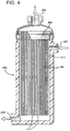
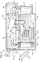
- FIG. 4 is a side elevational view of a contactor module 200.
- the module 200 receives beer into the shell side of the module through an inlet 202.
- the beer circulates throughout the shell side 212 of the module surrounding the fibers 206.
- the fibers 206 are hollow fibers which are non-flooding fibers thereby not allowing any beer to penetrate the fibers from the exterior, but having nitrogen supplied through an entry inlet 204 under pressure into the bores of the fibers.
- a tube sheet 208 seals the end of the module, however, the hollow fibers 206 penetrate the tubesheet and are open to receive the nitrogen through the entry inlet 204.
- the hollow fibers 206 are sealed shut, e.g. with a hot knife cut, at the ends of the fibers 210.
- the beer which enters the shell side 212 at the inlet 202 leaves the module under pressure at an exit port 214.
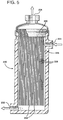
- FIG. 5 depicts a module suitable for use when it is desired to reduce the content of a dissolved gas in a liquid such as beer.
- the contactor module 220 has an entry port 222 for the beer to enter under pressure.
- the beer remains on the shell side 226 of the fibers 228 and passes carbon dioxide through the fibers 228 via mass transfer into the bores of the fibers where the excess carbon dioxide exits the module 220 through the port 224.
- the fibers 228 pass through the tubesheet 230 so that the excess carbon dioxide in the bores proceeds to the exit port 224.
- the fibers 228 are sealed at the other end 234, for example by means of a hot wire cut.
- the beer, reduced in carbon dioxide content exits from the module at a port 232.
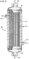
- FIG. 6 illustrates a contactor module 240 having an inlet 244 for a sweep gas e.g., nitrogen, which gas passes through the bores of the hollow fibers 252 and exits through an exit port 246.
- a sweep gas e.g., nitrogen
- a beverage e.g., beer
- the beer contains excess carbon dioxide which requires removal utilizing a sweep gas such as nitrogen.
- the module 240 has two tubesheets 250 which seal the ends of the module but gas can pass through the bores of the hollow fibers 252 because the hollow fibers extend through each of the tubesheets 250.
- the beer passes on the shell side 254 of the fibers and exits through an exit port 248.
- the module 240 is particularly suitable for use in the continuous flow mode.
- the flexibility of the present invention allows either or both treatments of beer to take place easily and economically.
- carbon dioxide is used as the pressure means to transport beer from the keg to the tap in the ordinary bar or restaurant
- continuing carbonation of the beer takes place and frequently elevates the carbonation to an undesirable point.
- the present invention allows for treatment of that beer to reduce the carbonation content to a predetermined desirable point.
- the beer within two days exposure quite easily may reach 3.5 volumes of carbon dioxide per volume of beer when it is maintained under a carbon dioxide pressure of about 34 psi. It is desirable that certain ales have only a volume of 1.2 to 1.5 dissolved carbon dioxide per volume of beer. Other ordinary beers require about 2.2 to 2.5 volumes of carbon dioxide per volume of beer.
- the simple procedure of passing the beer through the hollow fiber membrane module depicted in FIG. 5 allows the carbon dioxide content to be reduced to the predetermined selected amount.
- the module operates quite simply and the regulation of the carbon dioxide content is easily achieved. It is necessary however to have a module for controlling the carbon dioxide content for each of the beer lines because the desired carbon dioxide content is different for different beers.
- Nitrogenation of the beer is achieved utilizing the module depicted and described in FIG. 4 .
- the beer flows into the shell side of the hollow fibers in the module and receives nitrogen under pressure which diffuses through the hollow fiber membrane surfaces into the beer.
- the nitrogen is dissolved in the beer and hence provides no bubbles while the beer is in the module or the line prior to dispense.
- a particularly desirable process 260 is depicted in FIG. 7 .
- a single contactor module 298 is used.
- the module 260 is substantially the same as that depicted in FIG. 4.
- a keg 262 of beer 264 is cooled and maintained under pressure of a gas (either carbon dioxide or nitrogen or a combination of carbon dioxide and nitrogen) supplied from a gas source 266 through a line 268 to a control valve 270 and hence through another line 272 into the head space of the keg 262.
- the gas pressure is maintained at a predetermined level sufficient to provide adequate flow of the beer 264 through a line 280.
- the beer 264 flows from the line 280 through a check valve 282 and through another line 284 to a flow switch 290.
- the flow switch 290 cooperates with the control unit 336 such that when the dispense system 306 is activated, the flow switch 290 allows beer to flow into the contactor module 298 through the line 292 into the shell side entry port 294.
- the shell side of the fibers 296 in the contactor module 298 remains full of beer at all times under pressure whether the dispense system is drawing beer or whether the beer is static or motionless in the module.
- a gas supply line 312 is connected to a three-port control valve 314.
- the valve 314 has three ports 1, 2 and 3.
- the port 3 receives nitrogen and the connection between port 3 and port 2 is opened and closed in response to the control unit 336.
- a line 318 supplying nitrogen under pressure to the port 3 the nitrogen is maintained under a constant predetermined pressure controlled by the control valve 316.
- Nitrogen is supplied from a source 322 of nitrogen to the control valve 316 through a line 320.
- connection between the hollow fiber bores and the port 2 is open at all times and receives gas from the connection from the port 3 or the connection from the port 1 or from the hollow fiber bores through the line 312 when gas is being discharged from the bore side of the fibers as will be explained later.
- a second three-port control valve 324 has ports 4, 5 and 6.
- the port 5 of the valve 324 is connected by a line to the port 1 of the valve 314.
- Carbon dioxide is supplied from a source 332 under pressure through a line 330 to a pressure regulating valve 328, which is of the relieving type to a line 326.
- the carbon dioxide is maintained at a constant predetermined pressure in the line 326 controlled by the pressure regulating valve 328.
- the connection to the port 3 of the valve 314 closes and the connection to the port 1 opens simultaneously with the opening of the connections to the ports 5 and 6 to allow the excess nitrogen pressure to bleed from the fiber bores.
- the time required to reduce the bore pressure to substantially that of the atmosphere is dictated by the size of the internal passageways in the valve 314.
- the controls 336 are pre-set to allow that reduction in pressure before the operation of the valve 324 commences. This generally takes less than two seconds.
- connection to the port 6 closes and the connection to the port 4 opens to allow the flow of carbon dioxide from the port 1 to the connection to the port 2 into the module 298.
- connections to the ports 4 and 5 of the valve 324 open while the connections to the ports 1 and 2 of the valve 314 are open.
- the level of carbonation of the beer is controlled as discussed heretofore.
- connection to the port 4 of the valve 324 closes and the connection to the port 6 of the valve 324 opens to allow excess carbon dioxide to bleed from the bores of the hollow fibers 296 in the contactor module 298.
- connection to the port 1 closes and the connection to the port 3 of the valve 314 opens to again nitrogenate the static beer in the contactor module 298.
- the beer is nitrogenated when it is in a static state in the contactor module and any desired carbonation takes place while the beer is being dispensed.
- regulator valve 328 also operates to trim such over-carbonation. Carbon dioxide permeates from solution in the beer through the walls of the hollow fibers into the bore volume, and this excess carbon dioxide is vented at the relieving regulator valve 328 as it maintains the selected bore pressure in the module 298.
- the proportion of gas in the head space to liquid changes.
- the dissolved carbon dioxide content of the beer remains substantially level so that the first glass drawn from the keg and the last will be carbonated to substantially the same degree.
- nitrogen gas is used at 266 in FIG. 7 to displace a carbonated beer from a keg
- the quantity of carbon dioxide in the head space of the keg will change during dispense of its contents.
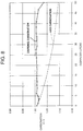
- the carbonation level of the beer will also be reduced, especially if the dispense pattern empties the keg slowly. This is delineated in FIG. 8 , where a 50 liter keg of beer was dispensed evenly over a period of six days according to the scheme of FIG. 7 , using nitrogen as the keg top pressure gas.
- the contactor module ideally should hold more than about 25% up to about 75% of the volume of one typical beer dispense. In this manner, the nitrogenated beer is swept from the module on each dispense thereby preventing nitrogen gradients along the length of the hollow fibers.
- the level of pre-dissolved nitrogen in a given type of beer is less critical to high quality dispense presentation than is the level of carbonation.
- the nitrogenation level may vary by a factor of two or so, e.g., from about 30 ppm to about 60 ppm by weight without impairing presentation of the dispensed beer.
- Carbonation levels should be maintained to within about 0.2 volume of the nominal level. Depending on the beer type, this nominal level will be set at a value between about 1.0 and about 2.5 carbon dioxide volumes per volume of beer.
- Control of carbonation in the present invention means either (1) the full addition of the required carbonation starting from zero or (2) incremental adjustment, up or down, to achieve the required nominal level.
- the dissolved gases, nitrogen and carbon dioxide are in bubble-less form and remain at the predetermined levels.
- the carbon dioxide bubbles and the nitrogen bubbles form to provide a head on the beer.
- nitrogen gas which has a low solubility and which has been pre-dissolved in beer at elevated pressure, very rapidly precipitates out of solution in a very fine dispersion of small bubbles. Larger carbon dioxide bubbles also are precipitated at the same time. The very small nitrogen bubbles float more slowly to the beer's surface than the larger carbon dioxide bubbles. Some nitrogen bubbles also nucleate precipitation of dissolved carbon dioxide gas which enters them causing them to grow and float faster. The small bubbles which collect at the surface contain nitrogen and a mixture of carbon dioxide and nitrogen gases. Because nitrogen is less able to permeate through the bubble's walls due to its low solubility these bubbles are relatively stable. Although the bubbles are losing carbon dioxide by permeation to the atmosphere, that loss tends to be made up by further carbon dioxide arriving from the bulk of the beer in the glass. Therefore the "head" on a nitrogenated beer lasts longer and is more appealing to most customers.
- the amount of nitrogen required is limited to the amount dissolved in the beer. For instance, if a bar or lounge were to dispense 10,000 gallons of beer with the amount of nitrogen being 50 ppm, the annual nitrogen usage utilizing the present invention would be less than 2 cubic meters compared with over 65 cubic meters of nitrogen if the same sales were made using a 50/50 mixed gas of nitrogen and carbon dioxide dispensing at 40 psig. Thus it can be seen that the present invention not only provides a more satisfactory product in the eyes of the customer but also conserves nitrogen.
- nitrogen is cheaper than carbon dioxide and brewers find flat beers easier to handle than fully carbonated beers.
- the dwell time of the beer typically three days under the pressure of nitrogen in the keg, little or no nitrogen is dissolved in the beer.
- the contact interface area needs to be large and the partial pressure of the gas in relation to the partial pressure of the same gas already dissolved in the liquid needs to be increased.
- a top pressure of a mixed nitrogen/carbon dioxide gas alternatively can be used to dispense keg beers.
- the carbon dioxide partial pressure is set to a predetermined level and nitrogen makes up the remainder pressure needed to transport the beer.
- nitrogen makes up the remainder pressure needed to transport the beer.
- there can be no appreciable dissolution of nitrogen into the beer so unless the beer is already nitrogenated by the brewery, use of the present invention is necessary to achieve the desired level of nitrogenation for satisfactory presentation of the beer.
- the carbonation level of the beer decreases to come into equilibrium with the carbon dioxide level in the head space in the keg.
- the carbonation level of the beer is substantially even. (See FIG. 8 )
- FIG. 9 depicts one embodiment in schematic form of the process of the present invention for the carbonation of water.
- the dispense system 410 is provided with a water source 412.
- the water is under a pressure of at least 20 psi and is transferred through a water line 414 to a check valve 416.
- the check valve 416 is closed until a demand is made on the system for carbonated water.
- the water after it has passed the check valve 416, flows through a water line 418, to a pre-cooler 420, which reduces the ambient temperature of the water to a temperature in the range of about 0° to about 10° C, preferably from about 0° C to about 4° C.
- the water from the pre-cooler 420 then enters the shell side of the module 424 where the water receives carbon dioxide from a carbon dioxide supply 426.
- the carbon dioxide flows from its source 426, through a primary pressure regulator 428, and then through a line 430, to the bore side of the hollow fibers in the module 424. It is preferred that the pressure of the carbon dioxide remain substantially constant.
- the carbonated water exits the module 424 through a line 440, to a carbonated water cooler line 446.
- the carbonated water is then transferred through a line 448, to the soda dispense valve 450.
- the soda dispense valve 450 acts in concert with the syrup dispense valve 468 and discharges the soda and syrup into the soda/syrup mixing chamber 452 where the soda and syrup are mixed before emptying into the beverage glass 470.
- a control box 464 controls each of the valves as well as the temperature controls. For instance, the control box 464 notifies the syrup dispense control 444 when to dispense syrup from syrup sources 454A, 454B, and 454C. Each of the syrups proceeds to its corresponding syrup pre-cooler 456A, 456B, and 456C. The syrup is then delivered from the pre-cooler 456A, 456B, or 456C, to the syrup dispense valve 468. The syrup and carbonator systems are activated by a request from the drink selection panel 466. In this system, the cooling takes place in an icebank 436, which is partially filled with icy water 438.
- the syrup and soda lines 448 and 456 and pre-coolers 420 and 446 are immersed in the icy water 438 along with the module 424.
- a refrigeration unit 460 controls the temperature in the icebank and chills the icebank through a refrigeration coil 458.
- the ice and water in the icebank 436 are stirred by an icebank stirrer 462.
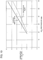
- FIG. 10 illustrates the surprising difference between carbonation, which can be attained on a continuous flow basis in comparison to that which is obtained when the system is in the dispense mode.
- the dispense mode for the present invention is controlled by the opening and closing of the dispense valve in concert with the check valve, which starts and stops the flow of water into the carbonation module.
- FIG. 10 illustrates the carbonation level attained in a module when the carbonated soda is in continuous flow and it also illustrates the carbonation attained when the system is in an intermittent dispense mode where 180 milliliter quantities of carbonated water are dispensed 6 times each minute.
- the flow rate of the carbonated water is 2.5 liters per minute, and the temperature is at 1° C. It is seen from FIG. 10 that the carbonation of the water is controlled by the carbon dioxide feed pressure.
- carbonation of water in a continuous flow mode produces 4.0 volumes of carbon dioxide for each volume of water.
- 50 psig of carbon dioxide produces a carbonation volume of about 4.85.
- FIG. 11 illustrates that following the moment of shut-off and the creation of snap pressure, carbonation of water within the module continues to take place, where the further increases in shell pressure result from expansion of soda as more carbon dioxide is absorbed by the water. It is indeed surprising that the level of carbonation thus produced is significantly greater than the levels predicted for the applied bore pressure as given in the published equilibrium data for a carbon dioxide/water system.
- FIG. 12 depicts this phenomenon, which is observed for all modules operated in the "check valve" configuration. This enhancement of carbonation is directly responsible for the results shown in FIG. 10 , where typical intermittent dispense carbonation is at a higher level than in the continuous flow carbonation process.
- FIG. 11 shows the rapid increase in shell pressure following the 'snap' effect that occurs as a result of continued carbonation following termination of a dispense action, the level of carbonation produced being contingent on the corresponding applied bore pressure of carbon dioxide.
- FIG. 11 significantly increased shell pressure occurs at approximately 40 psig carbon dioxide pressure. This corresponds with the dramatic increase in carbonation measured at and above 40 psig illustrated in FIG. 12 .
- the snap pressure effect and the resultant enhancement in carbonation are because of the action of the check valve. This configuration therefore enables use of a smaller, more compact module than would be predicted from data for continuous flow operation of the module.
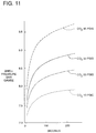
- FIG. 13 compares the carbonation level of soda with that of the Post Mix drink. The difference between the two curves is the result of gas loss as the soda flows through the final dispense valve and into the glass. This FIG. 13 illustrates that satisfactory drink carbonation levels can be obtained using the module to produce soda carbonation levels below 5 volumes of carbon dioxide for each volume of water. Conventional carbonators are designed to produce higher soda carbonation levels.
- the target soda carbonation from the module for Post Mix dispense application need not be greater than 6 v/v at a temperature of 1° C.
- the connections to, and control of, the module are very simple in practice.
- the shell volume has two ports, an inlet for water, and an outlet for soda, one at each end of the module to ensure that all active fiber surfaces are exposed to liquid flow.
- the fiber bores communicate with a third end port and this is connected to a pressure regulator fed with carbon dioxide gas.
- the fibers used in the module are characterized by a reasonable degree of permeability for carbon dioxide in bubble-less mass transfer.
- the hollow fiber membranes have an average pore size less than about 500 Angstroms as estimated by Knudsen's flow equation and a surface having less than 0.1% holes.
- the membranes are non-floodable and have a P/l for carbon dioxide greater than about 50 x 10 -6 to about 5,000 x 10 -6 cm 3 /cm 2 ⁇ sec ⁇ cmHg, and the module has at least about 25 sq cm of membrane surface per ml of liquid volume for a liquid flow rate of about 2 liters/minute.
- An increasing differential and thus higher carbonation values for a given water feed pressure can be achieved by decreasing the resistance to mass transfer through the liquid boundary layer. This can be accomplished by using a higher length/diameter aspect ratio for a given soda flow rate to increase the average fluid velocity. Alternatively, one might obtain the same improvements by employing different fiber geometry, e.g., by winding the fibers in a helical pattern to increase the nature of cross flow in the shell volume.
- conventional carbonators utilize high pressure water pumps.
- the high pressure performance of these pumps is needed in order to create the finely-divided spray which provides for a high surface area of contact with carbon dioxide gas in production of soda.
- this contact surface area is provided naturally and without consumption of power, by the fibers themselves.
- a water pump is only required in instances where the local supply pressure is insufficient to prevent breakout at the required carbon dioxide feed pressure needed for the target carbonation level.
- Soda dispense valves generally incorporate flow control mechanisms based on spring-adjustable variable-area orifices. These can also be used with the membrane module carbonators provided that the hydraulic feed pressure of soda at the module (i.e., effectively equal to the feed water pressure applied to the module) is within the control range of the dispense valve's flow control mechanism.
- an alternative means for controlling the flow rate of soda is to use a regulator to set the pressure of feed water applied to the module and to use only a fixed orifice in the soda dispense valve.
- a regulator to set the pressure of feed water applied to the module and to use only a fixed orifice in the soda dispense valve.
- these taps are connected via a soda manifold.
- a particular advantage of having a check valve in the water supply prior to its entering the shell side of the module is that a higher bore pressure of carbon dioxide can be used without break-out. For instance, if the shell pressure is 38 psig during a four-second dispense period, the maximum bore pressure could be raised to 75 psig with a check valve present, compared to 53 psig in a system which does not have a check valve. This demonstrates the capability of the check valve to control the system down stream of the check valve.
- the module It is generally preferred to operate the module with an applied bore pressure which is greater than that of the shell pressure during dispense flow (but not greater than the limit at which gas break-out occurs).
- the presence of the check valve will give rise to a shell pressure, the "snap" pressure, which is higher than the bore pressure, as explained earlier.
- the capillary pressures acting to fill and retain liquid in the very small pores in the fiber wall are large compared to the module's bore and shell operating pressures. Hence, there is found to be no transfer of liquid into the bores of the fibers within the suggested values of fiber specifications.
- a further preferred embodiment of the present invention includes a pressure-equalizing valve which prevents the shell pressure from exceeding that of the carbon dioxide feed gas.
- a pressure-equalizing valve which prevents the shell pressure from exceeding that of the carbon dioxide feed gas.
- Such a valve serves as a relief valve to prevent over pressurization of the shell, and additionally can be adapted to include a relief valve for the carbon dioxide feed.
- this valve does not affect the ability of the module to produce the enhanced carbonation effect which was discussed earlier (the data shown in FIG. 12 are measured with this valve in place). This is because the operating bore pressure, and hence the shell "snap" pressure, is generally set at above 40 psig.
- valve Since the soda volume downstream of the check valve is essentially incompressible, the valve will eject only a very small discharge of liquid at the end of each dispense.
- the valve may be located above the icebank's water level.
- the entire process of the present invention is bubble-less throughout until the liquid is dispensed. This is accomplished by using the process of the present invention and by utilizing hollow fiber membranes, which have certain characteristics, in the contactor modules.
- the membranes must be non-floodable under the pressure conditions of use. Since there is liquid on one side of the membrane and gas on the other, it is necessary that the liquid not flood the bores of the fibers. Also the membranes should have the characteristics heretofore discussed and have satisfactory permeability for each of carbon dioxide and nitrogen so as to permit useful rates of mass transfer of the gas to the liquid.
- the suggested range of P/l for carbon dioxide at 20° C in a dry state for membranes used in the present invention is from about 50 x 10 -6 to about 5,000 x 10 -6 cm 3 /cm 2 ⁇ sec ⁇ cmHg or more.
- a preferred range is from about 150 x 10 -6 to about 3,000 x 10 -6 cm 3 /cm 2 ⁇ sec ⁇ cmHg and the most preferred range is from about 300 x 10 -6 to about 1,000 x 10 -6 cm 3 /cm 2 ⁇ sec ⁇ cmHg.
- the hollow fiber membranes have an average pore size less than 500 Angstroms and a surface with less than 0.1% holes, the membranes being non-floodable and having a P/l for carbon dioxide greater than about 50 x 10 -6 to about 5,000 x 10 -6 cm 3 /cm 2 ⁇ sec ⁇ cmHg. These fibers allow permeation of nitrogen as well and are satisfactory for use in the present invention.
- the fibers be made from hydrophobic polymers.
- the polymeric membrane material is selected from substituted or unsubstituted polysulfone, polystyrene, acrylonitrile-styrene copolymer, styrene-butadiene copolymer, styrene-vinylbenzylhalide copolymer, polycarbonate, cellulose acetate, cellulose propionate, ethyl cellulose, methyl cellulose, nitrocellulose, polyamide, polyimide, aryl polyamide, aryl polyimide, polyether, polyetherimide, polyarylene oxide, polyphenylene oxide, polyxylylene oxide, polyesteramide-diisocyanate, polyurethane, polyester, polyarylate, polyethylene terephthalate, polyalkyl methacrylate, polyalkyl acrylate, polyphenylene terephthalate, polysulfide, polysiloxane, polyethylene, polypropylene, poly
- a keg of beer containing an ale type beer with an initial carbonation level of 1.0 carbon dioxide volume per volume of beer is connected to a carbon dioxide top pressure gas source at 28 psig. After 48 hours at 12 ° C., the carbonation level has increased to 2.9 v/v.
- a series of sample drinks, each with a volume of about 0.5 liter, are dispensed into clean glasses at a flow rate of 2 liters per minute.
- Both contactor modules contain membranes of polysulfone as heretofore described and are cooled by an external close fitting coil containing circulated cold water at about 4 ° C.
- the pressure setting of the carbon dioxide relief valve (# 70 FIG.
- the nitrogen feed pressure for the second module (# 86 FIG. 2 ) is set at 35 psig resulting in a beer having a dissolved nitrogen content of about 40 ppm.
- the drink samples are dispensed without breakout of bubbles in the delivery line upstream of the tap and without excessive foaming in the glass.
- a flow meter is attached to the outlet port of the relief valve (# 70 FIG. 2 ) which registers a flow of carbon dioxide gas as soon as the dispense tap is open, and the flow rapidly falls to zero upon closing of the dispense tap thus clearly signifying the removal of carbon dioxide from the ale.
- the head on the dispensed beer samples is a consistent white foam, approximately 0.5 inch thick, made up of small bubbles, which remain stable for 120 minutes with minimal reduction in its thickness.
- Example 2 Using the same beer described in Example 1, after it has been carbonated upon standing for 48 hours at 28 psig carbon dioxide pressure and 12° C, samples are dispensed via a tube connected directly to the dispense tap by-passing the membrane contactor modules. It is not possible to dispense the 0.5 liter samples without considerable waste due to excessive foaming in the glass.
- the head on the samples is less white in appearance than those in Example 1, and are made up of individual bubbles with a wide range of sizes, generally, much larger than those observed in Example 1.
- the heads, initially of equivalent thickness to those of Example 1, are also found to decay rapidly on standing. The dispensed beer's liquid layer is exposed after only 8 minutes.
- a lager beer with an initial carbonation of 2.4 v/v is connected to the same contactor module scheme as in Example 1, with a keg top pressure of 32 psig for 48 hours before dispensing drinks through the tap.
- the pressure of the relief valve is set at 15 psig and the nitrogen pressure is set at 30 psig.
- Samples are easily dispensed without excessive foaming.
- the head on the dispensed samples, about 0.5 liters each, is initially similar in appearance to those produced in Example 1.
- the foam is stable for a period of at least 35 minutes.
- Example 3 The lager beer used in Example 3 is dispensed directly by-passing the membrane contactor modules.
- the samples are dispensed with more foaming in the glass than in Example 3, and the heads are less white in appearance and are found to decay rapidly.
- the liquid surface is exposed in less than 5 minutes.
- the process of the present invention for the treatment of beer accomplishes (1) a maximum total head pressure on the keg in order to provide fast dispense flow rates; (2) the correct partial pressure of carbon dioxide in the beer to avoid over carbonation; and (3) the correct nitrogen partial pressure in the beer to provide nitrogenation and hence a stable head on the beer.
- the nitrogen gas is regulated at a pressure from about 20 to about 40 psi.
- the nitrogen partial pressure determines the ultimate concentration of nitrogen dissolved in the beer.
- the process of nitrogenation is about 50% completed in about 17 or 18 seconds and about 80% completed in about 40 seconds.
- a keg of proprietary ale type beer is cooled to 12.5° C and provided with a nominal 35 psig nitrogen top pressure.
- the beer is then transported to the apparatus shown in FIG. 7 and treated according to the procedure disclosed above for using this apparatus.
- the valve 316 provides a pressure of nitrogen of 35 psig and the valve 328 provides a pressure of carbon dioxide of 6 psig.
- the beer is carbonated to a level of about 1.4 v/v.
- FIG. 8 the results are shown for having drawn off beer over a six day period until the keg is substantially empty. It is clear that the present invention allows the beer to retain its proper carbonation during substantially the entire time the keg is being emptied.
- the dotted line in the graph depicts the usual degradation of the carbonation of the beer over the same time period, i.e., about six days for emptying.
- Modules are prepared in accordance with FIG. 4 containing polysulfone hollow fibers having the heretofore discussed characteristics and a P/l for carbon dioxide of at least 150 x 10 -6 cm 3 /cm 2 ⁇ sec ⁇ cmHg for carbon dioxide. Water is placed in the shell side of the membranes and carbon dioxide in the bores of the membranes at the pressures shown in the table below. The water is maintained at a temperature of 1-3° C. Each of the modules contains about 15 square feet of active membrane surface. The flow of soda is about 2 liters/minute when a drink is dispensed.
- Drinks containing about 200 ml of soda and syrup combined can be dispensed up to about 10 times per minute, but usually in commercial practice would not average much more than about 3 times per minute. In these examples the drinks are dispensed about every 20 seconds. Testing reveals that dispensing as many as 10 drinks/minute does not diminish the carbon dioxide content of the soda being dispensed. TABLE 1 Module No.
Landscapes
- Chemical & Material Sciences (AREA)
- Chemical Kinetics & Catalysis (AREA)
- Engineering & Computer Science (AREA)
- Water Supply & Treatment (AREA)
- Separation Using Semi-Permeable Membranes (AREA)
- Devices For Dispensing Beverages (AREA)
- Degasification And Air Bubble Elimination (AREA)
- Distillation Of Fermentation Liquor, Processing Of Alcohols, Vinegar And Beer (AREA)
Applications Claiming Priority (4)
| Application Number | Priority Date | Filing Date | Title |
|---|---|---|---|
| US40480795A | 1995-03-15 | 1995-03-15 | |
| US40480695A | 1995-03-15 | 1995-03-15 | |
| US404807 | 1995-03-15 | ||
| US404806 | 1995-03-15 |
Publications (2)
| Publication Number | Publication Date |
|---|---|
| EP0732142A2 true EP0732142A2 (fr) | 1996-09-18 |
| EP0732142A3 EP0732142A3 (fr) | 1998-06-17 |
Family
ID=27018772
Family Applications (1)
| Application Number | Title | Priority Date | Filing Date |
|---|---|---|---|
| EP96103808A Withdrawn EP0732142A3 (fr) | 1995-03-15 | 1996-03-11 | ContrÔle de la quantité de gaz dissous dans un liquide |
Country Status (3)
| Country | Link |
|---|---|
| US (1) | US5565149A (fr) |
| EP (1) | EP0732142A3 (fr) |
| JP (1) | JPH08276121A (fr) |
Cited By (21)
| Publication number | Priority date | Publication date | Assignee | Title |
|---|---|---|---|---|
| WO1998057733A1 (fr) * | 1997-06-14 | 1998-12-23 | Akzo Nobel N.V. | Module membranaire a membranes en fibres creuses enrobees d'un cote |
| EP0804881A3 (fr) * | 1996-05-01 | 2000-05-24 | L'air Liquide, Societe Anonyme Pour L'etude Et L'exploitation Des Procedes Georges Claude | Procédé de désinfection de légumes frais en les traítant par un liquide contenant un mélange argon; dioxyde de carbone |
| WO2000067886A1 (fr) * | 1999-05-05 | 2000-11-16 | Canzone Limited | Appareil et procede de melange de gaz et de liquide |
| US6209855B1 (en) | 1999-05-10 | 2001-04-03 | Canzone Limited | Gas/liquid mixing apparatus and method |
| EP1118276A3 (fr) * | 2000-01-20 | 2003-07-23 | Linde AG | Procédé pour la gazéification de liquide |
| WO2004039482A3 (fr) * | 2002-10-31 | 2004-07-29 | Craig L Glassford | Infusion de gaz atmospherique controlee |
| EP1635932A4 (fr) * | 2003-05-28 | 2006-07-26 | Entegris Inc | Procede et dispositif destines au traitement de fluides |
| EP1421988A4 (fr) * | 2001-08-28 | 2006-10-04 | Mitsubishi Rayon Co | Dispositif et procede pour la fabrication d'une source gazeifiee et d'eau gazeuse, procede de commande de la densite de gaz appliquee a cette eau et module a membrane |
| US7984845B2 (en) | 2008-05-19 | 2011-07-26 | Millercoors, Llc | Regulated fluid dispensing system packaging |
| US8038039B2 (en) | 2008-05-19 | 2011-10-18 | Millercoors, Llc | Regulated fluid dispensing device and method of dispensing a carbonated beverage |
| US8052012B2 (en) | 2008-05-19 | 2011-11-08 | Millercoors, Llc | Regulated fluid dispensing device and method of dispensing a carbonated beverage |
| US8191740B2 (en) | 2008-05-19 | 2012-06-05 | Millercoors, Llc | Modular constructed regulated fluid dispensing device |
| US8501008B2 (en) | 2005-09-09 | 2013-08-06 | Membrana Gmbh | Method for the elimination of leukocytes from blood |
| US8844909B2 (en) | 2008-05-19 | 2014-09-30 | Entegris, Inc. | Gasification systems and methods for making bubble free solutions of gas in liquid |
| EP2101843B1 (fr) * | 2007-01-13 | 2016-04-13 | 3M Innovative Properties Company of 3M Center | Dispositif d'élimination de leucocytes du sang |
| US10477883B2 (en) | 2015-08-25 | 2019-11-19 | Cornelius, Inc. | Gas injection assemblies for batch beverages having spargers |
| US10695482B2 (en) | 2011-10-14 | 2020-06-30 | Seastar Medical, Inc. | Cartridge and method for increasing myocardial function |
| US10785996B2 (en) | 2015-08-25 | 2020-09-29 | Cornelius, Inc. | Apparatuses, systems, and methods for inline injection of gases into liquids |
| US11040314B2 (en) | 2019-01-08 | 2021-06-22 | Marmon Foodservice Technologies, Inc. | Apparatuses, systems, and methods for injecting gasses into beverages |
| IT202000001429A1 (it) | 2020-01-24 | 2021-07-24 | Savese S R L | Dispositivo per addizionare anidride carbonica ad acqua |
| US11118162B2 (en) | 2010-10-15 | 2021-09-14 | Seastar Medical, Inc. | Cytopheresis cartridges and use thereof |
Families Citing this family (71)
| Publication number | Priority date | Publication date | Assignee | Title |
|---|---|---|---|---|
| US5971368A (en) | 1997-10-29 | 1999-10-26 | Fsi International, Inc. | System to increase the quantity of dissolved gas in a liquid and to maintain the increased quantity of dissolved gas in the liquid until utilized |
| US6332470B1 (en) * | 1997-12-30 | 2001-12-25 | Boris Fishkin | Aerosol substrate cleaner |
| GB9800904D0 (en) * | 1998-01-17 | 1998-03-11 | Bass Plc | Improvements relating to the delivery of flavoured alcoholic beverages |
| US6138995A (en) * | 1998-03-31 | 2000-10-31 | Permea, Inc. | Dispense of beverage containing controlled levels of dissolved gas |
| GB9808022D0 (en) * | 1998-04-16 | 1998-06-17 | Bass Plc | Improvements relating to the delivery of beverages |
| US7718102B2 (en) * | 1998-06-02 | 2010-05-18 | Praxair S.T. Technology, Inc. | Froth and method of producing froth |
| US6514301B1 (en) | 1998-06-02 | 2003-02-04 | Peripheral Products Inc. | Foam semiconductor polishing belts and pads |
| US6235641B1 (en) | 1998-10-30 | 2001-05-22 | Fsi International Inc. | Method and system to control the concentration of dissolved gas in a liquid |
| US6406551B1 (en) | 1999-05-14 | 2002-06-18 | Fsi International, Inc. | Method for treating a substrate with heat sensitive agents |
| EP1745838B1 (fr) * | 2000-04-18 | 2008-06-25 | Mitsubshi Rayon Engineering Co., Ltd | Procédé de fabrication d'eau gazeuse |
| GB0014435D0 (en) * | 2000-06-13 | 2000-08-09 | Air Prod & Chem | Method and apparatus for reducing foaming during fermentation |
| WO2002018037A2 (fr) * | 2000-08-31 | 2002-03-07 | Millipore Corporation | Structure de filtre avec event a gaz, comprenant un systeme de membrane a fibres creuses |
| AU2000278642A1 (en) * | 2000-10-05 | 2002-04-15 | Miller Brewing Company | Method of removing carbon dioxide from fermenting medium using a polymeric membrane |
| US6712342B2 (en) | 2001-10-26 | 2004-03-30 | Lancer Partnership, Ltd. | Hollow fiber carbonation |
| KR20030037344A (ko) * | 2001-11-01 | 2003-05-14 | 주식회사 한일아셈 | 중공사막식 탈기장치를 이용한 가성소다 수용액내의용존기체 제거방법 |
| US20050001340A1 (en) * | 2003-05-30 | 2005-01-06 | Page John K. | Apparatus for the preparation of liquids for the dispense of beverages |
| US20050129807A1 (en) * | 2003-12-12 | 2005-06-16 | Yuan James T.C. | Method and process of preserving alcoholic and carbonated beverage |
| US20060233922A1 (en) * | 2004-05-28 | 2006-10-19 | Andrew Kegler | Packaged flavor enhanced fruits or vegetables products with extended shelf-life for mass market distribution and consumption |
| DE102004041816B4 (de) * | 2004-08-30 | 2008-01-03 | Kwc Ag | Vorrichtung zur Karbonisierung und Kühlung von Getränken |
| US8153435B1 (en) | 2005-03-30 | 2012-04-10 | Tracer Detection Technology Corp. | Methods and articles for identifying objects using encapsulated perfluorocarbon tracers |
| DE102005062157B3 (de) * | 2005-12-22 | 2007-07-26 | Ankerbräu Nördlingen GmbH & Co. KG | Verfahren zur Herstellung von Bier |
| EP1829817A1 (fr) * | 2006-03-04 | 2007-09-05 | C.T.L. GmbH & Co.KG | Appareil pour soutirer des boissons et pour les mélanger avec des substances gazeuses et/ou aromatiques, et récipient pour boissons |
| US20070292568A1 (en) * | 2006-06-14 | 2007-12-20 | Kaufman Galen D | Dynamic modified atmosphere package system |
| USD585228S1 (en) | 2007-03-02 | 2009-01-27 | Wine Gadgets, Llc | Wine dispenser |
| US8033431B2 (en) | 2007-05-07 | 2011-10-11 | Wine Gadgets, Llc | Wine preservation and dispensing apparatus |
| US20090104308A1 (en) * | 2007-10-22 | 2009-04-23 | Gunter Waidelich | Methods and an apparatus for controlling concentrations of substances within wine |
| EP2053121A1 (fr) * | 2007-10-22 | 2009-04-29 | Inoxpa, S.A. | Procédés et appareil pour contrôler les concentrations de substances dans le vin |
| GB0800792D0 (en) * | 2008-01-16 | 2008-02-27 | Lancer Gb Llp | Liquid dispensing system |
| US20090188721A1 (en) * | 2008-01-30 | 2009-07-30 | Smith Kevin W | Membrane method of making drilling fluids containing microbubbles |
| NL1035235C2 (nl) * | 2008-03-31 | 2009-10-01 | Heineken Supply Chain Bv | Tapinrichting, voorzien van een drukregelinrichting. |
| WO2010059395A1 (fr) * | 2008-10-30 | 2010-05-27 | Porous Media Corporation | Système de ventilation et de filtration avec une membrane perméable au gaz |
| US20110000250A1 (en) * | 2008-12-22 | 2011-01-06 | Sommerfield Matthew A | Beverage preservation and dispensing apparatus incorporated within a refrigerator door |
| RU2406686C1 (ru) * | 2009-06-10 | 2010-12-20 | Сергей Александрович Бучик | Устройство для розлива пенящихся и/или газированных напитков в открытую тару |
| CH701558A2 (de) * | 2009-07-31 | 2011-01-31 | Alex Knobel | Vorrichtung und Verfahren zum Mischen und Austauschen von Fluiden. |
| JP5766212B2 (ja) | 2010-02-01 | 2015-08-19 | キューリグ グリーン マウンテン インク | カートリッジ式の飲料炭酸飽充方法およびその装置 |
| US9936834B2 (en) | 2010-02-01 | 2018-04-10 | Bedford Systems Llc | Method and apparatus for cartridge-based carbonation of beverages |
| US8438969B2 (en) * | 2010-05-06 | 2013-05-14 | Dr Pepper/Seven Up, Inc. | Apparatus and method for dissolving gases in a beverage |
| GB2496010B (en) * | 2011-10-25 | 2017-12-13 | Headmaster Ltd | Producing or dispensing liquid products |
| US20140076173A1 (en) * | 2012-04-05 | 2014-03-20 | Anheuser-Busch, Llc | Systems for introducing flavor to a non-carbonated base liquid |
| US9630826B2 (en) | 2013-06-07 | 2017-04-25 | The Coca-Cola Company | Beverage making machine |
| US9233824B2 (en) | 2013-06-07 | 2016-01-12 | The Coca-Cola Company | Method of making a beverage including a gas in a beverage making machine |
| US9265278B2 (en) * | 2013-06-24 | 2016-02-23 | Anheuser-Busch, Llc | Methods for decarbonating fermented liquids |
| WO2015021498A1 (fr) * | 2013-08-13 | 2015-02-19 | Breville Pty Limited | Saturateur |
| WO2015063792A1 (fr) * | 2013-11-02 | 2015-05-07 | Council Of Scientific & Industrial Research | Membranes asymétriques à base de bupbi |
| KR102455329B1 (ko) | 2014-05-15 | 2022-10-14 | 오토매틱 바 컨트롤즈, 인코포레이티드 | N₂ 주입 냉음료 분배 시스템 및 n₂ 주입 냉음료 준비 및 분배 방법 |
| US12351447B2 (en) * | 2014-05-15 | 2025-07-08 | Automatic Bar Controls, Inc. | Selectable gas infused beverage dispensing system |
| CA2895614A1 (fr) | 2014-06-23 | 2015-12-23 | Rehrig Pacific Company | Baril de biere en plastique |
| EP3106807B2 (fr) * | 2014-07-04 | 2021-06-02 | Lg Electronics Inc. | Appareil de production d'eau gazéifiée, réfrigérateur la comprenant et procédé pour le commander |
| US9327900B2 (en) | 2014-09-09 | 2016-05-03 | Keurig Green Mountain, Inc. | Method and apparatus for cartridge-based carbonation of beverages |
| EP3000780A1 (fr) * | 2014-09-26 | 2016-03-30 | Anheuser-Busch InBev S.A. | Ensemble de distribution de boissons comprenant un moyen de réception de conteneur ingrédient et un régulateur de pression de gaz |
| CA2965136A1 (fr) | 2014-10-20 | 2016-04-28 | Bedford Systems Llc | Circuit d'ecoulement pour machine a boissons gazeuses |
| US9364018B1 (en) | 2015-02-11 | 2016-06-14 | Keurig Green Mountain, Inc. | Adsorbent particle sizing for gas dissolution in beverages |
| US20180243699A1 (en) * | 2015-08-25 | 2018-08-30 | 3M Innovative Properties Company | Pvdf diffusion membrane for gas and liquid transfer |
| GB201520053D0 (en) * | 2015-11-13 | 2015-12-30 | Hartmann Frank | An apparatus for generating and infusing a gas into a liquid drink |
| US9955710B2 (en) | 2016-03-16 | 2018-05-01 | Cascade And Phoenix On Tap, Llc | Systems to nitrogen-infuse and dispense beverages |
| US10730023B2 (en) | 2016-03-16 | 2020-08-04 | Cuatro Connect Llc | Methods to nitrogen-infuse and dispense beverages |
| US10017373B2 (en) * | 2016-04-15 | 2018-07-10 | Automatic Bar Controls, Inc. | Nitrogen generator and uses thereof |
| US10228355B2 (en) | 2016-05-06 | 2019-03-12 | Board Of Regents, The University Of Texas System | Volatile eluent preparation |
| US10053350B2 (en) * | 2016-06-07 | 2018-08-21 | Cleland Sales Corporation | Post-mixing carbonation of beverages |
| WO2018085892A1 (fr) * | 2016-11-11 | 2018-05-17 | PTI Pacific Pty Ltd | Système modulaire de gazage et de dégazage de liquides |
| US10252900B2 (en) | 2016-12-07 | 2019-04-09 | Cornelius Beverage Technologies Limited | Apparatuses, systems, and methods for dispensing beverages using alcoholic concentrates |
| US11396446B2 (en) * | 2017-05-15 | 2022-07-26 | Gate Cfv Solutions, Inc. | High ratio fluid control |
| CN107335324A (zh) * | 2017-08-30 | 2017-11-10 | 武汉工程大学 | 一种管式多孔气‑液膜接触器 |
| CA3093554A1 (fr) * | 2018-03-15 | 2019-09-19 | Biotherm Hydronic, Inc. | Dispositifs modulaires, systemes d'infusion de gaz dans un liquide et procedes de fabrication et d'utilisation associes |
| US10618793B2 (en) | 2018-03-21 | 2020-04-14 | Enhanced Beverage Solutions | Beverage infuser |
| WO2019185718A1 (fr) | 2018-03-27 | 2019-10-03 | Carlsberg Breweries A/S | Système et procédé pour commander un niveau d'azote dans un récipient pour boisson |
| GB2574436A (en) * | 2018-06-06 | 2019-12-11 | Narino Ltd | Liquid processing system and method of operation |
| US10730735B2 (en) | 2018-09-24 | 2020-08-04 | Cornelius Beverage Technologies Limited | Alcoholic beverage dispensers with flow controls |
| US11613454B2 (en) * | 2018-12-28 | 2023-03-28 | Marmon Foodservice Technologies, Inc. | Beverage dispensers for dispensing mixed beverages with one or more gases injected therein |
| JP2021101655A (ja) * | 2019-12-25 | 2021-07-15 | Dic株式会社 | アルコール飲料の製造方法、注入方法、飲料及び飲料製造装置 |
| JP7700444B2 (ja) * | 2020-12-10 | 2025-07-01 | Dic株式会社 | 酒類の製造方法 |
Family Cites Families (21)
| Publication number | Priority date | Publication date | Assignee | Title |
|---|---|---|---|---|
| US3397871A (en) * | 1965-10-22 | 1968-08-20 | Hasselberg Inc | Carbonator |
| US3780198A (en) * | 1971-06-07 | 1973-12-18 | Crown Cork & Seal Co | System for carbonating beverages |
| US4364493A (en) * | 1979-08-15 | 1982-12-21 | Arthur Guinness Son And Company (Park Royal) Limited | Beverage dispensing system |
| US4517135A (en) * | 1983-06-21 | 1985-05-14 | Pepsico, Inc. | Carbonation measuring system and process |
| GB2172266B (en) * | 1985-03-11 | 1988-02-24 | Guinness Son And Company Arthu | Gasifying system for beverage dispenser |
| US4610888A (en) * | 1985-05-17 | 1986-09-09 | Anheuser-Busch Companies, Inc. | Beer foam enhancing process and apparatus |
| US5029733A (en) * | 1987-12-14 | 1991-07-09 | Guinness Brewing Worldwide Limited | Beverage dispensing system |
| DE68926421T2 (de) * | 1988-08-20 | 1996-09-12 | Nitto Denko Corp | Verfahren zur Entfernung von gelösten Gasen aus einer Flüssigkeit |
| US5059374A (en) * | 1989-02-09 | 1991-10-22 | The Dow Chemical Company | Method for sealing a hollow fiber membrane module in a case |
| JP2810694B2 (ja) * | 1989-04-20 | 1998-10-15 | 花王株式会社 | 浴湯用炭酸温水の生成方法及び装置 |
| US4927567A (en) * | 1989-06-23 | 1990-05-22 | The Coca-Cola Company | Motorless continuous carbonator |
| US4950431A (en) * | 1989-06-28 | 1990-08-21 | The Coca-Cola Company | Motorless batch carbonator |
| EP0447104A1 (fr) * | 1990-03-12 | 1991-09-18 | The BOC Group plc | Mise en solution d'un gaz dans un liquide |
| EP0470377B1 (fr) * | 1990-07-09 | 1995-05-24 | Dainippon Ink And Chemicals, Inc. | Membrane et appareil de contact gaz-liquide et procédé de préparation d'un liquide contenant un gaz dissous |
| GB9018533D0 (en) * | 1990-08-23 | 1990-10-10 | Whitbread & Co Plc | Methods and apparatus for dispensing beverages |
| WO1992009359A1 (fr) * | 1990-11-28 | 1992-06-11 | Mitsubishi Rayon Co., Ltd. | Membrane en polyethylene a fil creux poreux d'un grand diametre de pore, sa production et membrane en polyethylene a fil creux poreux hydrophile |
| GB2261383A (en) * | 1991-11-14 | 1993-05-19 | Calor Gas Ltd | Carbonator systems |
| FR2684088A1 (fr) * | 1991-11-22 | 1993-05-28 | Carboxyque Francaise | Procede de transfert d'un liquide a teneur en gaz dissous, en particulier de biere. |
| JPH05220480A (ja) * | 1992-02-10 | 1993-08-31 | Miura Co Ltd | 純水製造装置 |
| US5232601A (en) * | 1992-05-29 | 1993-08-03 | W. R. Grace & Co.-Conn. | High flux hollow fiber membrane |
| JPH07779A (ja) * | 1993-02-04 | 1995-01-06 | Mitsubishi Rayon Co Ltd | 炭酸ガス溶解方法及び装置 |
-
1996
- 1996-01-31 US US08/594,968 patent/US5565149A/en not_active Expired - Lifetime
- 1996-03-11 EP EP96103808A patent/EP0732142A3/fr not_active Withdrawn
- 1996-03-15 JP JP8087321A patent/JPH08276121A/ja active Pending
Cited By (37)
| Publication number | Priority date | Publication date | Assignee | Title |
|---|---|---|---|---|
| EP0804881A3 (fr) * | 1996-05-01 | 2000-05-24 | L'air Liquide, Societe Anonyme Pour L'etude Et L'exploitation Des Procedes Georges Claude | Procédé de désinfection de légumes frais en les traítant par un liquide contenant un mélange argon; dioxyde de carbone |
| US6270674B1 (en) | 1997-06-14 | 2001-08-07 | Akzo Nobel Nv | Membrane module with unilaterally embedded hollow fiber membranes |
| WO1998057733A1 (fr) * | 1997-06-14 | 1998-12-23 | Akzo Nobel N.V. | Module membranaire a membranes en fibres creuses enrobees d'un cote |
| AU778289B2 (en) * | 1999-05-05 | 2004-11-25 | Canzone Limited | Gas/liquid mixing apparatus and method |
| WO2000067886A1 (fr) * | 1999-05-05 | 2000-11-16 | Canzone Limited | Appareil et procede de melange de gaz et de liquide |
| US6209855B1 (en) | 1999-05-10 | 2001-04-03 | Canzone Limited | Gas/liquid mixing apparatus and method |
| EP1118276A3 (fr) * | 2000-01-20 | 2003-07-23 | Linde AG | Procédé pour la gazéification de liquide |
| US8096532B2 (en) | 2001-08-28 | 2012-01-17 | Mitsubishi Rayon Co., Ltd. | Device and method for manufacturing carbonated spring and carbonic water, control method for gas density applied thereto and membrane module |
| EP1421988A4 (fr) * | 2001-08-28 | 2006-10-04 | Mitsubishi Rayon Co | Dispositif et procede pour la fabrication d'une source gazeifiee et d'eau gazeuse, procede de commande de la densite de gaz appliquee a cette eau et module a membrane |
| US7237767B2 (en) | 2001-08-28 | 2007-07-03 | Mitsubishi Rayon Co., Ltd. | Device and method for manufacturing carbonated spring and carbonic water, control method for gas density applied thereto and membrane module |
| EP1837068A1 (fr) * | 2001-08-28 | 2007-09-26 | Mitsubishi Rayon Co., Ltd. | Dispositif et procédé pour la fabrication d'eau de source carbonée et carbonique, procédé de contrôle de la densité gazeuse appliquée à cette eau et module à membrane |
| US7334780B2 (en) | 2001-08-28 | 2008-02-26 | Mitsubishi Rayon Company, Limited | Device and method for manufacturing carbonated spring and carbonic water, control method for gas density applied thereto and membrane module |
| US7407154B2 (en) | 2001-08-28 | 2008-08-05 | Mitsubishi Rayon Co., Ltd. | Device and method for manufacturing carbonated spring and carbonic water, control method for gas density applied thereto and membrane module |
| WO2004039482A3 (fr) * | 2002-10-31 | 2004-07-29 | Craig L Glassford | Infusion de gaz atmospherique controlee |
| US7316728B2 (en) | 2003-05-28 | 2008-01-08 | Entegris, Inc. | Method and apparatus for treating fluids |
| EP1635932A4 (fr) * | 2003-05-28 | 2006-07-26 | Entegris Inc | Procede et dispositif destines au traitement de fluides |
| US8501008B2 (en) | 2005-09-09 | 2013-08-06 | Membrana Gmbh | Method for the elimination of leukocytes from blood |
| US9878085B2 (en) | 2005-09-09 | 2018-01-30 | 3M Innovative Properties Company | Method for the elimination of leukocytes from blood |
| EP2101843B1 (fr) * | 2007-01-13 | 2016-04-13 | 3M Innovative Properties Company of 3M Center | Dispositif d'élimination de leucocytes du sang |
| US7984845B2 (en) | 2008-05-19 | 2011-07-26 | Millercoors, Llc | Regulated fluid dispensing system packaging |
| US8191740B2 (en) | 2008-05-19 | 2012-06-05 | Millercoors, Llc | Modular constructed regulated fluid dispensing device |
| US8141755B2 (en) | 2008-05-19 | 2012-03-27 | Millercoors, Llc | Regulated fluid dispensing device and method of dispensing a carbonated beverage |
| US8844909B2 (en) | 2008-05-19 | 2014-09-30 | Entegris, Inc. | Gasification systems and methods for making bubble free solutions of gas in liquid |
| US8052012B2 (en) | 2008-05-19 | 2011-11-08 | Millercoors, Llc | Regulated fluid dispensing device and method of dispensing a carbonated beverage |
| US8038039B2 (en) | 2008-05-19 | 2011-10-18 | Millercoors, Llc | Regulated fluid dispensing device and method of dispensing a carbonated beverage |
| US8186569B2 (en) | 2008-05-19 | 2012-05-29 | Millercoors, Llc | Regulated fluid dispensing system packaging |
| US11118162B2 (en) | 2010-10-15 | 2021-09-14 | Seastar Medical, Inc. | Cytopheresis cartridges and use thereof |
| US12478923B2 (en) | 2010-10-15 | 2025-11-25 | Seastar Medical, Inc. | Cytopheresis cartridges and use thereof |
| US11866730B2 (en) | 2010-10-15 | 2024-01-09 | Seastar Medical, Inc. | Cytopheresis cartridges and use thereof |
| US10695482B2 (en) | 2011-10-14 | 2020-06-30 | Seastar Medical, Inc. | Cartridge and method for increasing myocardial function |
| US10722637B2 (en) | 2012-01-09 | 2020-07-28 | Seastar Medical, Inc. | Cartridge and method for increasing myocardial function |
| US11439739B2 (en) | 2012-01-09 | 2022-09-13 | Seastar Medical, Inc. | Cartridge and method for increasing myocardial function |
| US11013247B2 (en) | 2015-08-25 | 2021-05-25 | Marmon Foodservice Technologies, Inc. | Apparatuses, systems, and methods for inline injection of gases into liquids |
| US10785996B2 (en) | 2015-08-25 | 2020-09-29 | Cornelius, Inc. | Apparatuses, systems, and methods for inline injection of gases into liquids |
| US10477883B2 (en) | 2015-08-25 | 2019-11-19 | Cornelius, Inc. | Gas injection assemblies for batch beverages having spargers |
| US11040314B2 (en) | 2019-01-08 | 2021-06-22 | Marmon Foodservice Technologies, Inc. | Apparatuses, systems, and methods for injecting gasses into beverages |
| IT202000001429A1 (it) | 2020-01-24 | 2021-07-24 | Savese S R L | Dispositivo per addizionare anidride carbonica ad acqua |
Also Published As
| Publication number | Publication date |
|---|---|
| US5565149A (en) | 1996-10-15 |
| JPH08276121A (ja) | 1996-10-22 |
| EP0732142A3 (fr) | 1998-06-17 |
Similar Documents
| Publication | Publication Date | Title |
|---|---|---|
| US5565149A (en) | Control of dissolved gases in liquids | |
| US6138995A (en) | Dispense of beverage containing controlled levels of dissolved gas | |
| AU2012328207B2 (en) | Producing or dispensing liquid products | |
| US7104531B2 (en) | Apparatus for the preparation of liquids for the dispense of beverages | |
| EP0294199B1 (fr) | Système pour améliorer l'enrichissement en anhydride carbonique dans les appareils automatiques de boissons | |
| US11785968B2 (en) | System and method for deaerating beverages | |
| JPS61265080A (ja) | 麦芽飲料の発泡方法およびその分配用蛇口 | |
| JP2020506850A (ja) | ビール濃縮物から炭酸ビールを生成及び分配する方法 | |
| US3478929A (en) | Means for decarbonating and dispensing a beverage | |
| JPH05277348A (ja) | 液体への気体溶解方法 | |
| JP2000511139A (ja) | 容器の充填方法およびその装置 | |
| US20210023512A1 (en) | Gas entrainment system for beverages | |
| JPH08175599A (ja) | ポストミツクス飲料供給装置 | |
| JPH053207Y2 (fr) | ||
| AU2007203139A1 (en) | Dispensing apparatus | |
| NZ620209B2 (en) | Producing or dispensing liquid products |
Legal Events
| Date | Code | Title | Description |
|---|---|---|---|
| PUAI | Public reference made under article 153(3) epc to a published international application that has entered the european phase |
Free format text: ORIGINAL CODE: 0009012 |
|
| AK | Designated contracting states |
Kind code of ref document: A2 Designated state(s): DE FR GB |
|
| PUAL | Search report despatched |
Free format text: ORIGINAL CODE: 0009013 |
|
| AK | Designated contracting states |
Kind code of ref document: A3 Designated state(s): DE FR GB |
|
| 17P | Request for examination filed |
Effective date: 19980827 |
|
| 17Q | First examination report despatched |
Effective date: 20050329 |
|
| STAA | Information on the status of an ep patent application or granted ep patent |
Free format text: STATUS: THE APPLICATION HAS BEEN WITHDRAWN |
|
| 18W | Application withdrawn |
Effective date: 20101115 |