EP0731376A1 - Récipient pour un produit photosensible sous forme de bande - Google Patents
Récipient pour un produit photosensible sous forme de bande Download PDFInfo
- Publication number
- EP0731376A1 EP0731376A1 EP96420054A EP96420054A EP0731376A1 EP 0731376 A1 EP0731376 A1 EP 0731376A1 EP 96420054 A EP96420054 A EP 96420054A EP 96420054 A EP96420054 A EP 96420054A EP 0731376 A1 EP0731376 A1 EP 0731376A1
- Authority
- EP
- European Patent Office
- Prior art keywords
- container
- spindle
- container according
- roll
- rolls
- Prior art date
- Legal status (The legal status is an assumption and is not a legal conclusion. Google has not performed a legal analysis and makes no representation as to the accuracy of the status listed.)
- Granted
Links
Images


Classifications
-
- G—PHYSICS
- G03—PHOTOGRAPHY; CINEMATOGRAPHY; ANALOGOUS TECHNIQUES USING WAVES OTHER THAN OPTICAL WAVES; ELECTROGRAPHY; HOLOGRAPHY
- G03B—APPARATUS OR ARRANGEMENTS FOR TAKING PHOTOGRAPHS OR FOR PROJECTING OR VIEWING THEM; APPARATUS OR ARRANGEMENTS EMPLOYING ANALOGOUS TECHNIQUES USING WAVES OTHER THAN OPTICAL WAVES; ACCESSORIES THEREFOR
- G03B27/00—Photographic printing apparatus
- G03B27/32—Projection printing apparatus, e.g. enlarger, copying camera
- G03B27/52—Details
- G03B27/58—Baseboards, masking frames, or other holders for the sensitive material
- G03B27/587—Handling photosensitive webs
- G03B27/588—Supply rolls; Cutting arrangements
Definitions
- the invention concerns a container adapted for transporting photosensitive products in strip form.
- the invention is particularly suited to the transportation of such photosensitive products between sites manufacturing photosensitive products and processing laboratories using such products in the production, for example on paper, of photographic prints.
- photosensitive products in strip form are transported in distribution packaging which, besides the transportation function, also provides for the unwinding of the product under lightproof conditions in order to be used by processing laboratories.
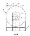
- FIG. 1 depicts such packaging diagrammatically.
- This comprises principally a base 17 adapted for being handled by a fork lift truck, a rigid casing 21 designed to protect the strip product, and a cantilevered spindle 10 fixed to the base 17 by means of a frame 40.
- the casing 21 forms substantially a cylinder and is closed off by an end cover (not depicted) which, when it is removed, leaves clear the free end of the cantilevered spindle so as to enable rolls of products in strip form to be inserted.
- the distribution packaging also has a lightproof slot 60 enabling the product in strip form to be extracted when it is used, for example, in a photographic printer.
- the slot 60 is made lightproof in a conventional manner by means of baize or another suitable foam complex.
- the top part 61 defining the slot is hinged by means of a hinge 62, thus, by tilting of the top part 61, affording easy access to the strips disposed on the spindle 10.
- the container also comprises locking means (not depicted) enabling the rolls of photosensitive products on the cantilevered spindle to be immobilised/freed selectively.
- these locking means include mechanisms with cams and corresponding cam followers.
- Such locking elements must be accessible from the outside for, as required, immobilising or freeing, at least with respect to rotation, each of the spools, independently of each other, so as to enable the strip product to be extracted through the slot.
- a major advantage of this type of distribution packaging lies in its ease of use by operators working with photographic printers.
- distribution packaging for photosensitive products are described, for example, in the documents EP-A-0 214 928, US-A-4 741 439, US-A-3 315 910 and FR-A 1 551 085.
- one of the objects of the present invention is to provide a container for the transportation of photosensitive products in strip form that offers substantially the same ease of use as the packaging described above, while substantially resolving the problems referred to previously, notably those relating to cost.
- Another object of the present invention is to provide a container designed to receive a plurality of rolls and which has an unloading mechanism including means for indicating, at any moment, the number of rolls already unloaded.
- a container (1) for a photosensitive product in strip form wound on a spool comprising:
- the means (7, 13, Fig 3) for driving the roll out of the cylindrical enclosure are able to be actuated from outside the container, the cylindrical enclosure and the spindle both being adapted for receiving a plurality of rolls of the said photosensitive product in strip form.
- the container also comprises means (11) for enabling it to be immobilised with respect to an unwinding unit (9) designed to receive the said roll of photosensitive product, the said unwinding unit (9) having a receiving spindle (10) which is brought into alignment with the said projecting spindle (6) so as to receive the said roll from the said container.
- the driving means comprise a ring (7) mounted so as to be able to be moved along the said projecting spindle (6) by means of driving devices (13) enabling the roll or rolls to be pushed out of the container through the said opening, the said driving devices (13) being able to be actuated from outside the container.
- the container according to the invention is, in reality, the result of a double observation: on the one hand, the major part of the cost of a conventional transportation/unwinding unit is attributable to the operation of unwinding and distributing the film, the transportation function affecting its cost only to a much lower degree; and, on the other hand, the number of units needed for the transportation of film is significantly greater than the number of units needed for the unwinding of the photosensitive product in order to use it in a photographic printer.
- FIG. 2 illustrates schematically a preferred embodiment of the container 1 according to the present invention.
- This comprises principally a lightproof cylindrical case 3.
- the case preferably takes the form of a right-angled parallelepiped so as to enable the containers to be stacked, notably in order to facilitate their transportation.
- the container preferably has a base or pallet footing 15 adapted to handling by a fork lift truck.
- At least one of the end walls 4 can be opened so as to define an end opening 8 for inserting one or more rolls 2 of products in strip form wound on spools 14.
- the door 4 pivots about a vertical axis.
- the container according to the invention also comprises a cantilevered spindle 6 designed to receive the roll or rolls.
- the spindle is mounted so as to project perpendicularly to the end walls 4, 5.
- the cantilevered spindle is mounted on the base 15 by means of a frame (not depicted) consisting of angle sections and plates welded together so as to keep the spindle 6 projecting.
- a frame not depicted
- Other well-known means are possible for the mounting of the spindle.
- Various materials can be used to produce such a container. For example, steel or plastic are used.
- the container can include locating members 70 for improving the stability of a stack of several containers (by preventing the containers from sliding on each other).
- the container has means enabling the rolls to be transferred easily from the container 3 to an unwinding unit of the type that has just been described with reference to Figure 1. The latter consequently requires no additional description.
- FIG. 3 illustrates schematically the container according to the invention and shows a preferred embodiment of the container unloading device.
- the means enabling the rolls to be unloaded include principally a pusher device, a ring 7, preferably, or a finger, mounted on the spindle 6, and arranged so as to push the roller or rollers out of the container through the opening 4 so as to transfer them onto the corresponding spindle of an unwinding unit.
- the ring is driven by means of a screw 13 which is disposed inside the spindle 6 and whose movement enables the ring 7 to move along the spindle 6.
- a reversible drive system is used so as to permit the automatic return of the ring 7 to the bottom of the container during the reloading of the container under the pressure of the rolls against the ring.
- the screw is preferably able to be actuated from the outside, for example by means of a screwing/unscrewing device 50 or any other suitable means.
- the ring can be driven by means of a pressure cylinder, which can be connected to a pressurised fluid source disposed outside the container.
- a finger or pin is used in place of the ring.
- Such a finger is driven by the screw and mounted so as to be able to move in translation on the spindle.
- the unloading means could be able to be actuated from the outside, it is clear that this is not an essential feature.
- the ring could be driven by means of an electric motor, whose operation could be controlled by a switch situated inside the container and to which an operator could have access when the door 4 is open.
- the pusher device may also be desirable to couple the pusher device to means designed to determine its position along the spindle 6 so as to be able to unload a predetermined number of rolls.
- a revolution counter is used whose output represents the number of rolls unloaded (or the number of rolls not yet unloaded), the width of the spools on each of the rolls preferably being constant.
- the screw is connected to the revolution counter by a transmission system whose transmission ratio in rotation will be adjusted according to the precision desired in the result displayed by the counter.
- the counter can indicate a value corresponding just to a whole number of rolls or, preferably, indicate a value corresponding to the number of rolls already transferred plus a decimal or centesimal fraction corresponding to the position of the roll being transferred.
- revolution counters which can be used according to the present invention are the models DA08 and DA09, which are digital position indicators for direct mounting on a shaft, marketed by SIKO GmbH.
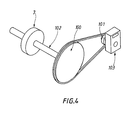
- the transmission system comprises two pulleys 100, 101 disposed between the screw 102 and the revolution counter 103.
- the first pulley 100 connected directly to the screw 102, is controlled by the movement of the screw 102.
- the second pulley disposed between the first one 100 and the revolution counter 103, is controlled by the movement of the first pulley.
- serrated pulleys are used, the ratio of the respective number of teeth on the pulleys 100, 102 being chosen so as to give the desired transmission ratio. The latter characteristic is particularly advantageous when the container contains more than one roll and when the container is not to be unloaded fully. Other devices with sensors can be used.
- the immobilisation of the rotation of the rolls loaded in the container is effected by actuating the ring 7 after the door 4 has been closed so as to move it a sufficient distance to enable the rolls to be locked between the door 4, or any other stop means provided for this purpose, and the ring.
- a non-reversible screw is preferably used. The latter characteristic constitutes a simple and efficacious means of immobilising the rolls inside the containers, notably during their transportation.
- an interposed support able to move between the spool and the spindle, can be used.
- an interposed system consists of a strip of material having a coefficient of friction less than that of the spool, and upon which the rolls are placed, the strip being driven in synchronism with the pusher device.
- the container 1 and the unwinding unit 9 are arranged so that the free ends of their respective spindles are aligned. All these operations are, of course, carried out under inactinic light.
- the alignment is effected by means of guide rails 16 (fixed to the floor) designed to receive the respective bases 17 and 15 of the unwinding unit 9 and the container 1.
- the unit 9 is then immobilised with respect to the container by means of locking devices 11 provided on the base of the container and/or of the unwinding unit, which cooperate with recesses or notches provided on the guide rails.
- the alignment and immobilisation are effected through cooperation between appropriate mechanical devices (guide rods, grooves, hooks, etc) disposed directly on the container and on the unwinding unit. This avoids the use of auxiliary rails.
- the unloading means (7, 13, 50) are actuated so as to transfer the rolls from the spindle 6 to the spindle 10.
- the cover of the unwinding unit is then closed again. The latter is then ready to be used in a photographic printer, in the manner described in detail in Patent Application EP-A-0 532 590.
- the container is low in cost compared with conventional containers; the use of this container, whose sole function is transportation, compared with the use of distribution packagings, does not substantially complicate the task of the operators handling these products.
- the number of unwinding units required for the functioning of processing laboratories is reduced considerably (one unit per photographic printer), which substantially improves the overall efficiency of the transportation operation in terms of cost.
- the container and the unwinding unit can have, at their respective end openings, means (baffles, flexible lips, slots, bellows) designed to cooperate with each other, so as to be able to allow the rolls to be unloaded under actinic light.
- means baffles, flexible lips, slots, bellows
- means are provided on the container for rotatably locking the body of the screwing/unscrewing device with respect to the container so as to avoid any "back kick" that might be very hurtful for an operator.
- the door pivots about a horizontal axis.
- the door may be comprised of a flexible material (such as plastic) mounted on a frame that is designed to light-tightly fit with the opening of the container, with or without any joint.
Landscapes
- Physics & Mathematics (AREA)
- General Physics & Mathematics (AREA)
- Packaging Of Machine Parts And Wound Products (AREA)
- Photographic Developing Apparatuses (AREA)
- Storage Of Web-Like Or Filamentary Materials (AREA)
Applications Claiming Priority (2)
| Application Number | Priority Date | Filing Date | Title |
|---|---|---|---|
| FR9502785A FR2731527B1 (fr) | 1995-03-06 | 1995-03-06 | Container pour produit photosensible en bande |
| FR9502785 | 1995-03-06 |
Publications (2)
| Publication Number | Publication Date |
|---|---|
| EP0731376A1 true EP0731376A1 (fr) | 1996-09-11 |
| EP0731376B1 EP0731376B1 (fr) | 2002-05-29 |
Family
ID=9476914
Family Applications (1)
| Application Number | Title | Priority Date | Filing Date |
|---|---|---|---|
| EP96420054A Expired - Lifetime EP0731376B1 (fr) | 1995-03-06 | 1996-02-16 | Récipient pour un produit photosensible sous forme de bande |
Country Status (5)
| Country | Link |
|---|---|
| US (1) | US5680202A (fr) |
| EP (1) | EP0731376B1 (fr) |
| JP (1) | JPH08286321A (fr) |
| DE (1) | DE69621366T2 (fr) |
| FR (1) | FR2731527B1 (fr) |
Cited By (1)
| Publication number | Priority date | Publication date | Assignee | Title |
|---|---|---|---|---|
| EP0843205A1 (fr) * | 1996-11-15 | 1998-05-20 | Eastman Kodak Company | Structure en étanche à la lumière |
Families Citing this family (2)
| Publication number | Priority date | Publication date | Assignee | Title |
|---|---|---|---|---|
| FR2755953B1 (fr) * | 1996-11-15 | 1999-02-05 | Kodak Pathe | Systeme de securite |
| DE10014842A1 (de) * | 2000-03-24 | 2001-09-27 | Heidelberger Druckmasch Ag | Vorrichtung zum Lagern, Transportieren und Zuführen von flächigem Bedruckstoff für eine diesen verarbeitende Maschine |
Citations (4)
| Publication number | Priority date | Publication date | Assignee | Title |
|---|---|---|---|---|
| CH446048A (fr) * | 1963-10-04 | 1967-10-31 | Photostat Corp | Appareil photographique |
| DE3538048A1 (de) * | 1984-10-25 | 1986-04-30 | Fuji Photo Film Co., Ltd., Minami-Ashigara, Kanagawa | Einrichtung zum herstellen von fotoabzuegen auf fortlaufendem fotopapier |
| WO1991019222A1 (fr) * | 1990-06-08 | 1991-12-12 | Kodak-Pathe | Emballage de produits photographiques en bandes |
| EP0661586A2 (fr) * | 1993-12-28 | 1995-07-05 | Canon Kabushiki Kaisha | Dispositif de chargement et de déchargement d'une cartouche de film |
Family Cites Families (3)
| Publication number | Priority date | Publication date | Assignee | Title |
|---|---|---|---|---|
| JPS61219040A (ja) * | 1985-03-25 | 1986-09-29 | Fuji Photo Film Co Ltd | 写真感光材料収納マガジン |
| FR2658156B1 (fr) * | 1990-02-12 | 1992-06-12 | Kodak Pathe | Procede d'emballage, emballage et dispositif de manutention des produits en bandes. |
| DE59206990D1 (de) * | 1991-08-13 | 1996-10-02 | Agfa Gevaert Ag | Fotografisches Kopiergerät mit einer Vorratskassette |
-
1995
- 1995-03-06 FR FR9502785A patent/FR2731527B1/fr not_active Expired - Fee Related
- 1995-12-22 US US08/577,290 patent/US5680202A/en not_active Expired - Fee Related
-
1996
- 1996-02-16 DE DE69621366T patent/DE69621366T2/de not_active Expired - Fee Related
- 1996-02-16 EP EP96420054A patent/EP0731376B1/fr not_active Expired - Lifetime
- 1996-03-06 JP JP8049051A patent/JPH08286321A/ja active Pending
Patent Citations (5)
| Publication number | Priority date | Publication date | Assignee | Title |
|---|---|---|---|---|
| CH446048A (fr) * | 1963-10-04 | 1967-10-31 | Photostat Corp | Appareil photographique |
| DE3538048A1 (de) * | 1984-10-25 | 1986-04-30 | Fuji Photo Film Co., Ltd., Minami-Ashigara, Kanagawa | Einrichtung zum herstellen von fotoabzuegen auf fortlaufendem fotopapier |
| WO1991019222A1 (fr) * | 1990-06-08 | 1991-12-12 | Kodak-Pathe | Emballage de produits photographiques en bandes |
| EP0532590A1 (fr) * | 1990-06-08 | 1993-03-24 | Kodak Pathe | Emballage de produits photographiques en bandes. |
| EP0661586A2 (fr) * | 1993-12-28 | 1995-07-05 | Canon Kabushiki Kaisha | Dispositif de chargement et de déchargement d'une cartouche de film |
Cited By (3)
| Publication number | Priority date | Publication date | Assignee | Title |
|---|---|---|---|---|
| EP0843205A1 (fr) * | 1996-11-15 | 1998-05-20 | Eastman Kodak Company | Structure en étanche à la lumière |
| FR2756062A1 (fr) * | 1996-11-15 | 1998-05-22 | Kodak Pathe | Structure en u etanche a la lumiere |
| US5901849A (en) * | 1996-11-15 | 1999-05-11 | Eastman Kodak Company | U-shaped light-tight structure |
Also Published As
| Publication number | Publication date |
|---|---|
| JPH08286321A (ja) | 1996-11-01 |
| DE69621366T2 (de) | 2003-01-02 |
| FR2731527A1 (fr) | 1996-09-13 |
| US5680202A (en) | 1997-10-21 |
| DE69621366D1 (de) | 2002-07-04 |
| EP0731376B1 (fr) | 2002-05-29 |
| FR2731527B1 (fr) | 1997-05-09 |
Similar Documents
| Publication | Publication Date | Title |
|---|---|---|
| US5509522A (en) | Quick release hopper and improved cylindrical dispensing member for individual cigarette vending machine | |
| JPH03223838A (ja) | フィルムシート装荷マガジン | |
| JP3310066B2 (ja) | フイルムカートリッジ輸送装置 | |
| EP4108608A2 (fr) | Système de retrait pour retirer des articles d'une boîte d'emballage | |
| JPH08122946A (ja) | カセットの割出し装置、記憶発光体要素の読取り装置及び記憶発光体プレートの読取り消去方法 | |
| US5005689A (en) | Storage system | |
| EP0731376B1 (fr) | Récipient pour un produit photosensible sous forme de bande | |
| US5660384A (en) | Imaging unit container having shiftable walls | |
| US5560597A (en) | Imaging unit container including bag clamping member | |
| US5382129A (en) | Sheet feed device for an image forming apparatus | |
| EP0714045A1 (fr) | Méthode et dispositif pour manipuler des cassettes pour l'alimentation de moyens de grand format | |
| US4393642A (en) | Sheet receiving and storage apparatus | |
| US4734743A (en) | Light tight slidable transport for transferring light sensitive materials | |
| US5358115A (en) | Dark box for storage of exposed light sensitive sheets | |
| JPS62286049A (ja) | フイルム供給装置 | |
| JP2546742Y2 (ja) | フイルム装填装置 | |
| US5132725A (en) | Photographic copying machine for use with mobile cassettes | |
| JP2954772B2 (ja) | 除去した包装シートを包装シート収納手段に収納可能な画像形成装置の給紙装置 | |
| JP2812734B2 (ja) | シャッタ装置 | |
| JPS634543Y2 (fr) | ||
| JP2846201B2 (ja) | フイルム供給方法及びフイルム供給装置 | |
| JPS62286048A (ja) | フイルム供給装置 | |
| JPH02106731A (ja) | 特にプリンターのための、フイルム巻き付け及び巻き戻し装置 | |
| US3753515A (en) | Slide transparency spreading device | |
| JPS62286050A (ja) | フイルム供給装置 |
Legal Events
| Date | Code | Title | Description |
|---|---|---|---|
| PUAI | Public reference made under article 153(3) epc to a published international application that has entered the european phase |
Free format text: ORIGINAL CODE: 0009012 |
|
| AK | Designated contracting states |
Kind code of ref document: A1 Designated state(s): BE DE FR GB NL |
|
| 17P | Request for examination filed |
Effective date: 19970213 |
|
| RAP1 | Party data changed (applicant data changed or rights of an application transferred) |
Owner name: EASTMAN KODAK COMPANY |
|
| GRAG | Despatch of communication of intention to grant |
Free format text: ORIGINAL CODE: EPIDOS AGRA |
|
| 17Q | First examination report despatched |
Effective date: 20010828 |
|
| GRAG | Despatch of communication of intention to grant |
Free format text: ORIGINAL CODE: EPIDOS AGRA |
|
| GRAH | Despatch of communication of intention to grant a patent |
Free format text: ORIGINAL CODE: EPIDOS IGRA |
|
| GRAH | Despatch of communication of intention to grant a patent |
Free format text: ORIGINAL CODE: EPIDOS IGRA |
|
| GRAA | (expected) grant |
Free format text: ORIGINAL CODE: 0009210 |
|
| AK | Designated contracting states |
Kind code of ref document: B1 Designated state(s): BE DE FR GB NL |
|
| REG | Reference to a national code |
Ref country code: GB Ref legal event code: FG4D Free format text: NOT ENGLISH |
|
| REF | Corresponds to: |
Ref document number: 69621366 Country of ref document: DE Date of ref document: 20020704 |
|
| ET | Fr: translation filed | ||
| PLBE | No opposition filed within time limit |
Free format text: ORIGINAL CODE: 0009261 |
|
| STAA | Information on the status of an ep patent application or granted ep patent |
Free format text: STATUS: NO OPPOSITION FILED WITHIN TIME LIMIT |
|
| 26N | No opposition filed |
Effective date: 20030303 |
|
| PGFP | Annual fee paid to national office [announced via postgrant information from national office to epo] |
Ref country code: GB Payment date: 20040107 Year of fee payment: 9 |
|
| PGFP | Annual fee paid to national office [announced via postgrant information from national office to epo] |
Ref country code: NL Payment date: 20040112 Year of fee payment: 9 |
|
| PGFP | Annual fee paid to national office [announced via postgrant information from national office to epo] |
Ref country code: FR Payment date: 20040202 Year of fee payment: 9 |
|
| PGFP | Annual fee paid to national office [announced via postgrant information from national office to epo] |
Ref country code: DE Payment date: 20040227 Year of fee payment: 9 |
|
| PGFP | Annual fee paid to national office [announced via postgrant information from national office to epo] |
Ref country code: BE Payment date: 20040518 Year of fee payment: 9 |
|
| PG25 | Lapsed in a contracting state [announced via postgrant information from national office to epo] |
Ref country code: GB Free format text: LAPSE BECAUSE OF NON-PAYMENT OF DUE FEES Effective date: 20050216 |
|
| PG25 | Lapsed in a contracting state [announced via postgrant information from national office to epo] |
Ref country code: BE Free format text: LAPSE BECAUSE OF NON-PAYMENT OF DUE FEES Effective date: 20050228 |
|
| BERE | Be: lapsed |
Owner name: *EASTMAN KODAK CY Effective date: 20050228 |
|
| PG25 | Lapsed in a contracting state [announced via postgrant information from national office to epo] |
Ref country code: NL Free format text: LAPSE BECAUSE OF NON-PAYMENT OF DUE FEES Effective date: 20050901 Ref country code: DE Free format text: LAPSE BECAUSE OF NON-PAYMENT OF DUE FEES Effective date: 20050901 |
|
| GBPC | Gb: european patent ceased through non-payment of renewal fee |
Effective date: 20050216 |
|
| PG25 | Lapsed in a contracting state [announced via postgrant information from national office to epo] |
Ref country code: FR Free format text: LAPSE BECAUSE OF NON-PAYMENT OF DUE FEES Effective date: 20051031 |
|
| NLV4 | Nl: lapsed or anulled due to non-payment of the annual fee |
Effective date: 20050901 |
|
| REG | Reference to a national code |
Ref country code: FR Ref legal event code: ST Effective date: 20051031 |
|
| BERE | Be: lapsed |
Owner name: *EASTMAN KODAK CY Effective date: 20050228 |