EP0731053A2 - Aufzugstürsystem - Google Patents
Aufzugstürsystem Download PDFInfo
- Publication number
- EP0731053A2 EP0731053A2 EP96301526A EP96301526A EP0731053A2 EP 0731053 A2 EP0731053 A2 EP 0731053A2 EP 96301526 A EP96301526 A EP 96301526A EP 96301526 A EP96301526 A EP 96301526A EP 0731053 A2 EP0731053 A2 EP 0731053A2
- Authority
- EP
- European Patent Office
- Prior art keywords
- door
- coupling
- car
- landing
- plate
- Prior art date
- Legal status (The legal status is an assumption and is not a legal conclusion. Google has not performed a legal analysis and makes no representation as to the accuracy of the status listed.)
- Granted
Links
Images





Classifications
-
- B—PERFORMING OPERATIONS; TRANSPORTING
- B66—HOISTING; LIFTING; HAULING
- B66B—ELEVATORS; ESCALATORS OR MOVING WALKWAYS
- B66B13/00—Doors, gates, or other apparatus controlling access to, or exit from, cages or lift well landings
-
- B—PERFORMING OPERATIONS; TRANSPORTING
- B66—HOISTING; LIFTING; HAULING
- B66B—ELEVATORS; ESCALATORS OR MOVING WALKWAYS
- B66B13/00—Doors, gates, or other apparatus controlling access to, or exit from, cages or lift well landings
- B66B13/02—Door or gate operation
- B66B13/12—Arrangements for effecting simultaneous opening or closing of cage and landing doors
Definitions
- This invention relates to an elevator door system, and more particularly to an elevator door system in which a landing door is opened or closed in one unit with a car door.
- a conventional elevator entrance is generally composed of jamb, a car door, a landing door and others.
- the car door and the landing door are in such a relation that the car door unlocks the locking of the landing door and is coupled with the landing door when an elevator car lands a landing floor and thus, the landing door opens/closes jointly with the opening/closing motion of the car door.
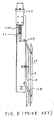
- FIGs. 9 and 10 show the backs of a car door 4 and a landing door 1 when doors 4 and 1 are closed, respectively.
- each of landing doors 1 is kept locked by a locking lever 3 of a locking device 2 when it is kept closed.
- a retiring cam 6 at the car door side provided on the end of a car frame 5 operates to unlock the locking of landing doors 1.
- An unlocking roller 9 is provided at an end of a header case 7 of landing doors 1 corresponding to the position of a bow 8 of retiring cam 6.
- a shaft 9B is provided in header case 7.
- Unlocking roller 9 is attached at one end of shaft 9B via a lever 9A.
- Unlocking levers 3 are attached to shaft 9B and two positions. When unlocking roller 9 is pushed by bow 8 of retiring cam 6, shaft 9B is rotated and thereby the locking of landing doors 1 by locking levers 3 is unlocked.
- Fig. 11(a) shows the locked state of retiring cam 6 and landing door 1 when landing door 1 is closed and the car is traveling
- Fig. 11(b) shows the unlocked state of retiring cam 6 and landing door 1 when landing door 1 is opened.
- Locking mechanism of landing door 1 is in the construction as described below.
- retiring cam 6 is in such a state wherein bow 8 has been retracted by lifting a rod 11 by exciting a solenoid (an electromagnet) 10, as shown in Fig. 11(a) and in a chain double-dashed line in Fig. 8.
- a solenoid an electromagnet
- solenoid 10 of retiring cam 6 is released according to a command from a controller (not shown), and thereby rod 11 is pushed downward by a spring 12A and blow 8 is pushed forward by the rotation of link 12B as shown in a continuous line in Figure 8.
- unlocking roller 9 of landing door 1 is pushed by bow 8 as shown in Fig. 11(b)
- shaft 9B is rotated counterclockwise via lever 9A, and thereby locking lever 3 which is restricting landing door 1 from moving, is rotated to unlock the locking of landing door 1.
- bow 8 pushes continuously unlocking roller 9.
- Landing door 1 is coupled with car door 4 by a coupling plate 12 of landing door 1 and a coupling device 13 of car door 4 as shown in Figs. 9 and 10. That is, when a door machine 14 provided on the car frame is operated, a lever 15 rotates counterclockwise, a link 17 with a pin 17A on car frame 5 used as a supporting point is rotated via a rod 16, and a cam 18 which is made in one united body with a small link 18A rotates around the supporting point. Then, as a lever 19 of coupling device 13 rotates counterclockwise (in case of coupling device 13 positioned at the right in Fig. 9) a coupling roller 20 comes close to a stationary roller 21, and thereby rollers 20, 21 couple car door 4 and landing door 1 by putting coupling plate 12 between them.
- the conventional elevator door system constructed as described above is capable of achieving a stabilized high speed door opening/closing, as the landing door panel and the car door panel are respectively driven in the vicinity of their centers of gravity, thereby promoting the operating efficiency of an elevator, however, it has such problems as described below.
- the unlocking roller is also installed at the end of the landing door, and as a result, the breadthwise size of a hoistway becomes large.
- the header case of the landing door becomes in complicated construction and cost will become high.
- one object of this invention is to provide an elevator door system wherein it is possible to save the elevator installing space.
- Another object of this invention is to provide an elevator door system having a simple construction.
- Still another object of this invention is to provide an elevator door system which can be installed and adjusted easily.
- an elevator door system including a landing door, a car door provided on a car, a latch device for locking the landing door when the landing door is closed.
- the elevator door system also includes a door locking device provided on the landing door composed of a coupling plate for coupling with the car door, an unlocking plate provided in parallel with the coupling plate, and a link connected between the coupling plate and the unlocking plate for moving the unlocking plate toward the coupling plate.
- the elevator door system further includes a first linking mechanism for linking the door locking device with the latch device, and a coupling device provided on the car door composed of a pair of coupling rollers for coupling the car door with the landing door, when the car lands a landing floor and the door locking device is positioned between the coupling rollers.
- One of the coupling rollers of the coupling device pushes the unlocking plate toward the coupling plate when the car lands the landing floor.
- a displacement of the unlocking plate caused by being pushed toward the coupling plate by the link is applied to the latch device through the first linking mechanism.
- the latch device unlocks the landing door when the displacement of the unlocking plate is applied.
- the coupling device couples the car door with the landing door by pushing the door locking device between the coupling rollers of the coupling device when the car lands the landing floor and after the landing door is unlocked, and the car door and the landing door are moved in one unit after the coupling device couples the car door with the landing door.
- an elevator door system constructed as described below.
- a latch is provided at the center above the landing door for locking the landing door when the landing door is closed.
- a coupling device is provided on the car door in which two coupling rollers operate to come up to each other through a link mechanism when a cam is rotated.
- an unlocking plate is provided on the landing door which is coupled with parallel links and is restricted only to the parallel movement in parallel with a coupling plate.
- the latch is connected to parallel links via a connecting rod.
- a door machine is covered with a cover so that its upper plate is usable as a scaffold.
- a link lever in the door machine is designed not to project out of the cover when it is operated.
- the landing door is unlocked and is coupled with the car door by holding the coupling plate and the unlocking plate with coupling rollers of the coupling device of the car door, and thus, the landing door and the car door are opened/closed.
- the cover of the door diving device eliminates the possibility of hand and foot being caught by the link lever and makes a working space on the car wide.
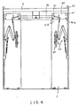
- Figs. 1 and 2 show respectively front views of the back of a car door according to an embodiment of this invention when the car door is closed (in Fig. 1) and is opened (in Fig. 2).
- a door system of car door 4 is composed of a door machine 14A composed of a motor and reduction mechanism, an output rod 16 connecting thereto, a large link 17 for opening/closing car door 4 and a coupling device 13A for coupling with landing door 1.
- Door machine 14A is assembled by covering its mechanical portion with a cover 22 which is also used as a scaffold.
- a lever 15A rotates around the center of a sprocket 14a but is in length that does not projecting upward from cover 22 used as a scaffold.
- Coupling device 13A which is provided to car door 4 is in such a construction as described below.
- Figs. 5A and 5B show front views of coupling device 13A of car door 4 according to an embodiment of this invention when it is closed (in Fig. 5A) and it is opened (in Fig. 5B).
- coupling device 13A is composed of a link A having a pin 23a on a base screwed to the panel of car door 4 and a link B which also has a pin 24a on the base, a link C which connects link A and link B via pins 26a and 27a, and a spring 24.
- a rubber roller 20 is attached to the other end of link A via a pin 23b and, a rubber roller 21B is attached to the other end of link B via a pin 24b.
- Spring 24 is connected to the top of link A and restricts the movement of two rubber rollers 20 and 21B in the state wherein a follower 23 is kept pushed against a cam 18 by connecting link A and link B.
- a small link 18A is connected to large link 17.
- Cam 18 connected to small link 18A in one united body rotates on a pin 36a.
- Door coupling device 13A is so composed that small link 18A is set at an initial angle ⁇ 1 (an angle when a door is closed as shown in Fig. 5A), and when a door is opened rollers 20, 21B become in the state as shown in Fig.
- Figs. 3 and 4 show respectively front views of the back of a landing door according to an embodiment of this invention when the landing door is closed (in Fig. 3) and is opened (in Fig. 4).
- landing door 1 is opened/closed on a rail 39 provided on a stationary frame 37 at the building side while being suspended from rollers 41 provided on a hanger 40 at the upper part of landing door 1.
- a door locking device 25 coupled to coupling plate 12 in one united body is assembled to the panel, and further a closer 43 which is constantly applying a closing force to the panel of landing door 1 and the like are provided.
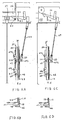
- Figs. 6A and 6B show front views of door locking device 25 of landing door 1 according to an embodiment of this invention when it is closed (in Fig. 6A) and it is opened (in Fig. 6C). Furthermore, Figs. 6B and 6D show respectively views of Figs. 6A and 6C in the direction of arrows X.
- Door locking device 25 of landing door 1 is assembled to conventional coupling plate 12 in one united body.
- Links 26, 27 respectively rotate with pins 47, 48 used as supporting points, which are erected on a base 46 of coupling plate 12.
- Link 26 is in the V-shaped and its one end is projecting to the right side of base 46 from the notch of the base 46.
- An unlocking plate 28 is attached to links 26, 27 at supporting point of links 26, 27 via rotary pins 47a, 48a.
- Unlocking plate 28 is a thin plate and is bent, for example, in the L-shape to keep the strength.
- a rod 29 is connected to another supporting point 47c of link 26 via a bracket 53 and the upper end of rod 29 is connected to the rear end of a latch 30.
- Latch 30 is constantly latched on a door lock 32 (a latch bracket) at the landing floor side by a tension spring 31 and balance of gravity.
- latch 30 As the end of latch 30 is kept latched on door lock 32 (the latch bracket) of a switch box 56 when landing door 1 is closed, landing door 1 cannot be opened from the landing floor side.
- the end of latch 30 is provided with a metal piece which short-circuits a door switch 57 when closing the door, and a car travel OK signal is sent to the controller (not shown).
- latch 30 has been lifted up by the unlocking motion as shown in Figs. 6C and 6D, this signal is not sent and therefore, the car cannot travel.
- a rubber plate 58 adhered to coupling plate 12 side by a bonding agent or a double-sided tape between coupling plate 12 and unlocking plate 28 thereby to reduce noise which is generated when both metallic plates of coupling plate 12 and unlocking plate 28 strike each other.
- Coupling plate 12 and unlocking plate 28 are in such lengths that landing door 1 and car door 4 are able to open/close at a difference in levels of landing positions between the landing floor sill and the car sill, which is determined by regulations.
- the length of rod 29 is adjustable by changing the nut fastening positions at both ends or one end of rod 29 so as to make a gap between coupling plate 12 and unlocking plate 28 to a proper dimension.
- lever 15A is longer than lever 15B, or a weight (not shown) is attached to near the tip portion of lever 15A, so as to generate a closing power when closing car doors 4.
- the plate of car door 4 is installed so that rollers 16a rotate on a rail 17a fixed to car frame 5 and rollers 90a, 90b are provided below rail 17a, and the panel is restricted to move only in the horizontal direction.
- link levers 15A, 15B rotate counterclockwise and pull rod 16 to rotate large link 17 which has a supporting point 11a on car frame 5.
- small link 18A which is connected to cam 18 at a supporting point 36a on coupling device 13A fixed to the panel of car door 4, rotates to operate coupling device 13A by cam 18, thus opening the panel of car door 4.
- rollers 20, 21B of coupling device 13A move to come near each other according to the movement of follower 23 of which position is restricted by cam 18.
- the panel of landing door 1 is moved in the horizontal direction only by rollers 41 over rail 39 and rollers 91a, 91b under rail 39 along rail 39 of header case 7 on frame 37 fixed to a building, as shown in Figs. 3 and 4.
- unlocking plate 28 When opening the door, unlocking plate 28 is moved laterally by roller 21B of coupling device 13A and is pushed toward coupling plate 12. Then, links 26, 27 rotate clockwise around respective pins 47, 48 to pull rod 29 downward, and thereby latch 30 rotates to unlock landing door 1.
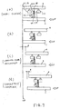
- Fig. 7(a) shows the operating positional relation between rollers 20, 21B of coupling device 13A and door locking device 25 when doors 1, 4 are closed and the car passes.
- rollers 20, 21B When door machine 14A is operated, the panel of car door 4 first begins to move. Interlocking with this movement, rollers 20, 21B also move to come near each other, and then roller 21B of coupling device 13A at the central side of the entrance contacts unlocking plate 28 and becomes the state shown in Fig. 7(b).
- roller 21B pushes unlocking plate 28 against rubber plate 58 of coupling plate 12 and becomes the state shown in Fig. 7(c), wherein landing door 1 is unlocked. This state is shown in Fig. 6C.
- the panel of landing door 1 is driven in the opening direction by roller 21B and becomes the state shown in Fig. 7(b) when doors 1, 4 are fully coupled.
- a difference in level (a gap) ⁇ between the panels of car door 4 and landing door 1 becomes smaller than a difference in level ⁇ when unlocked as shown in Fig. 7(c). This is because the panel of landing door 1 of which position is restricted by coupling roller 21B catches up to the panel of car door 4 as the velocity of coupling roller 21B to the ground is larger than that of the panel of car door 4 to the ground by the operation of coupling device 13A until doors 1, 4 are fully coupled.
- Difference in level ⁇ can be freely set if the moving ratios of rollers 20, 21B are changed by changing the lengths of links A, B and C and the position of pins 23a, 24a, 26a and 27a of coupling device 13A shown in Figs. 5A and 5B.
- the panel of car door 4 As the panel of car door 4 is coupled with the panel of landing door 1 in one united body in the state shown in Fig. 7(d), it becomes possible to drive the panels of doors 1, 4 at a high speed during the subsequent opening operation. Before becoming the state shown in Fig. 7(d), the panel of landing door 1 is in the unstable state, because it is within the range of clearance between coupling rollers 20, 21B, so that it is not possible to drive the panels of doors 1, 4 at a high speed as the vibration of doors 1, 4 is anticipated.
- Figs. 2 and 4 show car door 4 and landing door 1 in the fully opened state, respectively.
- doors 1, 4 when they are closed is entirely contrary to the above-description, and doors 1, 4 are closed from the open state in the order as shown in Fig. 7(d), (c), (b), and (a).
- Door locking device 25 when doors 1, 4 are closed is in the state as shown in Fig. 6A.
- unlocking plate 28 functions to rotate link 26 counterclockwise by its own weight, and therely unlocking plate 28 functions to push rod 29 up to maintain latch 30 in the state where it is latched on lock 32. Therefore, even if spring 31 is broken latch 30 will never be put in the unstable state.
- car door 4 can be composed by making the horizontal distance between coupling rollers 20, 21B and angle ⁇ of cam 18 in common dimensions and by changing the lengths of large link 17 and rod 16, the positions of the supporting points on link levers 15A, 15B and the position of the supporting point of car frame 5, etc.
- the width and height of the panel of landing door 1 and the width of hanger 40 are to be changed.
- the length of rod 29 should be changed so as to set the center of coupling plate 12 at the height equal to the heights of rollers 20, 21B of coupling device 13A of car door 4.
- the elevator door system is composed of center opening car doors 4 and center opening landing doors 1.
- This invention is, however, not limited to this embodiment.
- This invention can be applied to an elevator door system composed of a side opening car door and a side opening landing door.
- the present invention can simplify the entrance door and the locking device, improve reliability of the locking and unlocking, save the elevator space and facilitate the installing and adjustment work.
Landscapes
- Elevator Door Apparatuses (AREA)
Applications Claiming Priority (3)
| Application Number | Priority Date | Filing Date | Title |
|---|---|---|---|
| JP05094195A JP3260055B2 (ja) | 1995-03-10 | 1995-03-10 | エレベータ出入口戸の開閉装置 |
| JP5094195 | 1995-03-10 | ||
| JP50941/95 | 1995-03-10 |
Publications (3)
| Publication Number | Publication Date |
|---|---|
| EP0731053A2 true EP0731053A2 (de) | 1996-09-11 |
| EP0731053A3 EP0731053A3 (de) | 1997-02-26 |
| EP0731053B1 EP0731053B1 (de) | 2002-06-05 |
Family
ID=12872858
Family Applications (1)
| Application Number | Title | Priority Date | Filing Date |
|---|---|---|---|
| EP96301526A Expired - Lifetime EP0731053B1 (de) | 1995-03-10 | 1996-03-06 | Aufzugstürsystem |
Country Status (9)
| Country | Link |
|---|---|
| US (1) | US5690188A (de) |
| EP (1) | EP0731053B1 (de) |
| JP (1) | JP3260055B2 (de) |
| KR (1) | KR100190433B1 (de) |
| CN (1) | CN1045186C (de) |
| DE (1) | DE69621496T2 (de) |
| MY (1) | MY126332A (de) |
| SG (1) | SG64341A1 (de) |
| TW (1) | TW386065B (de) |
Cited By (2)
| Publication number | Priority date | Publication date | Assignee | Title |
|---|---|---|---|---|
| EP1671917A1 (de) * | 2004-12-20 | 2006-06-21 | Inventio Ag | Aufzugsanlage mit Schachttüre und Türschliessvorrichtung |
| US8746412B2 (en) | 2008-12-19 | 2014-06-10 | Otis Elevator Company | Elevator door frame with electronics housing |
Families Citing this family (24)
| Publication number | Priority date | Publication date | Assignee | Title |
|---|---|---|---|---|
| FI100517B (fi) * | 1995-09-13 | 1997-12-31 | Kone Oy | Menetelmä hissin tasonoven sulkemisessa ja mukaanottaja |
| US6070700A (en) * | 1997-09-16 | 2000-06-06 | Inventio Ag | Operating system for elevator doors |
| KR100286356B1 (ko) * | 1998-12-15 | 2001-05-02 | 장병우 | 엘리베이터 도어의 계합장치 |
| US6220396B1 (en) * | 2000-03-10 | 2001-04-24 | Thyssen Dover Elevator | Door restrictor apparatus for elevators |
| US6508332B2 (en) | 2000-11-15 | 2003-01-21 | Fujitec America, Inc. | Elevator car door locking and unlocking mechanism |
| KR100462453B1 (ko) * | 2004-06-18 | 2004-12-17 | 유병배 | 엘리베이터 출입문장치 |
| EP1841681B1 (de) * | 2005-01-28 | 2014-04-09 | Mitsubishi Denki Kabushiki Kaisha | Vorrichtung zur verriegelung von aufzugskabinen |
| WO2007030092A2 (en) * | 2005-09-01 | 2007-03-15 | Otis Elevator Company | Door suspension assembly |
| JP4907355B2 (ja) * | 2006-02-03 | 2012-03-28 | 三菱電機株式会社 | エレベータのドア装置 |
| KR100848516B1 (ko) | 2008-03-07 | 2008-07-25 | 주식회사 세명엘리베이터 | 상/하 개폐식 엘리베이터용 도어장치 |
| EP2287103B1 (de) * | 2008-06-16 | 2015-09-09 | Mitsubishi Electric Corporation | Aufzugskabinentürverriegelung |
| US8226180B2 (en) * | 2008-12-04 | 2012-07-24 | General Electric Company | Door coupling system |
| US9663329B2 (en) * | 2012-06-18 | 2017-05-30 | Sematic S.P.A. | Lift cages with improved blocking/releasing devices |
| CN102718117A (zh) * | 2012-06-19 | 2012-10-10 | 苏州汾湖电梯有限公司 | 一种电梯门厅门装置 |
| CN103291133B (zh) * | 2013-06-21 | 2015-03-25 | 无锡海德曼医疗设备有限公司 | 安全门锁装置 |
| CN103552899B (zh) * | 2013-11-15 | 2016-08-17 | 广东升达电梯有限公司 | 一种连杆式电梯门开关 |
| CN107473061B (zh) | 2016-06-08 | 2020-10-16 | 奥的斯电梯公司 | 升降电梯系统的维护安全装置及其操作方法 |
| CN106185560B (zh) * | 2016-08-31 | 2018-11-27 | 艾瑞斯股份有限公司 | 高速梯轿门防风降噪结构 |
| JP6541046B1 (ja) * | 2018-10-12 | 2019-07-10 | フジテック株式会社 | エレベータ用ドア装置 |
| CN110642128A (zh) * | 2019-09-27 | 2020-01-03 | 法斯特电梯有限公司 | 一种新型电梯门机 |
| US11453573B2 (en) | 2020-03-03 | 2022-09-27 | Fujitec Co., Ltd. | Elevator door engagement device |
| JP6864876B1 (ja) * | 2020-12-15 | 2021-04-28 | フジテック株式会社 | エレベータのドア係合装置 |
| JP6751534B1 (ja) * | 2020-03-03 | 2020-09-09 | フジテック株式会社 | エレベータドア開閉用のかごドア係合装置 |
| JP7371715B2 (ja) * | 2022-03-16 | 2023-10-31 | フジテック株式会社 | エレベーターの強制戸開装置 |
Family Cites Families (5)
| Publication number | Priority date | Publication date | Assignee | Title |
|---|---|---|---|---|
| US2307353A (en) * | 1940-12-13 | 1943-01-05 | Wagner Mfg Company | Elevator |
| US3065826A (en) * | 1958-07-30 | 1962-11-27 | Otis Elevator Co | Entranceway apparatus and closure means for elevators |
| ATE75458T1 (de) * | 1988-03-18 | 1992-05-15 | Inventio Ag | Tuerantriebsvorrichtung mit verriegelungsmechanismus fuer aufzuege. |
| JPH04164797A (ja) * | 1990-10-29 | 1992-06-10 | Toshiba Corp | エレベータ |
| JP2930512B2 (ja) * | 1993-11-18 | 1999-08-03 | 東芝エフエーシステムエンジニアリング株式会社 | エレベータのドア |
-
1995
- 1995-03-10 JP JP05094195A patent/JP3260055B2/ja not_active Expired - Fee Related
-
1996
- 1996-03-05 US US08/610,932 patent/US5690188A/en not_active Expired - Fee Related
- 1996-03-06 DE DE69621496T patent/DE69621496T2/de not_active Expired - Fee Related
- 1996-03-06 EP EP96301526A patent/EP0731053B1/de not_active Expired - Lifetime
- 1996-03-07 TW TW085102802A patent/TW386065B/zh not_active IP Right Cessation
- 1996-03-08 SG SG1996006120A patent/SG64341A1/en unknown
- 1996-03-08 MY MYPI96000862A patent/MY126332A/en unknown
- 1996-03-08 CN CN96102742A patent/CN1045186C/zh not_active Expired - Fee Related
- 1996-03-11 KR KR1019960006368A patent/KR100190433B1/ko not_active Expired - Fee Related
Cited By (2)
| Publication number | Priority date | Publication date | Assignee | Title |
|---|---|---|---|---|
| EP1671917A1 (de) * | 2004-12-20 | 2006-06-21 | Inventio Ag | Aufzugsanlage mit Schachttüre und Türschliessvorrichtung |
| US8746412B2 (en) | 2008-12-19 | 2014-06-10 | Otis Elevator Company | Elevator door frame with electronics housing |
Also Published As
| Publication number | Publication date |
|---|---|
| DE69621496D1 (de) | 2002-07-11 |
| MY126332A (en) | 2006-09-29 |
| JP3260055B2 (ja) | 2002-02-25 |
| CN1137482A (zh) | 1996-12-11 |
| EP0731053A3 (de) | 1997-02-26 |
| CN1045186C (zh) | 1999-09-22 |
| EP0731053B1 (de) | 2002-06-05 |
| US5690188A (en) | 1997-11-25 |
| TW386065B (en) | 2000-04-01 |
| KR100190433B1 (ko) | 1999-06-01 |
| DE69621496T2 (de) | 2002-10-24 |
| KR960034056A (ko) | 1996-10-22 |
| SG64341A1 (en) | 1999-04-27 |
| JPH08245143A (ja) | 1996-09-24 |
Similar Documents
| Publication | Publication Date | Title |
|---|---|---|
| US5690188A (en) | Elevator door system | |
| US6340073B1 (en) | Elevator door system | |
| JP5940220B2 (ja) | エレベータのかごドアロック装置 | |
| JP6250190B2 (ja) | エレベータのかごドア装置 | |
| RU2462409C2 (ru) | Замок двери кабины | |
| US6484850B1 (en) | Elevator control panel device | |
| CA2009934C (en) | Elevator car with improved door lock | |
| EP0850189B1 (de) | Verfahren zur betätigung einer aufzugsschachttür und türkupplungsvorrichtung | |
| JP4245371B2 (ja) | エレベータのドア装置 | |
| KR100286356B1 (ko) | 엘리베이터 도어의 계합장치 | |
| JP4038067B2 (ja) | ロック装置を有するエレベーターのかご室ドア装置 | |
| CN100379671C (zh) | 电梯的乘厅门装置 | |
| JP7631580B1 (ja) | エレベータドアのインターロック装置 | |
| JP7529175B1 (ja) | エレベータのかごドア開閉装置及びエレベータ | |
| JP2507651Y2 (ja) | 斜行エレベ―タのドア係合装置 | |
| JP3014862B2 (ja) | エレベーターかご戸ロツク装置 | |
| CA2590356C (en) | Car door lock | |
| KR20020095981A (ko) | 엘리베이터용 커플러의 도어닫힘 안정화장치 | |
| JPH05330770A (ja) | エレベーターのかごの戸ロック装置 | |
| JPH07115815B2 (ja) | 斜行エレベータのドア係合装置 | |
| JP2005188055A (ja) | プラットホームドアの施錠装置 | |
| KR20010039275A (ko) | 엘리베이터의 승장 도어 개방장치 | |
| JPH10273277A (ja) | エレベーターの戸閉スイッチ装置 | |
| KR20060066095A (ko) | 연장가능한 문지방을 가진 승강기 조립체 | |
| KR19980060494U (ko) | 엘리베이터용 승장도어 잠금장치 |
Legal Events
| Date | Code | Title | Description |
|---|---|---|---|
| PUAI | Public reference made under article 153(3) epc to a published international application that has entered the european phase |
Free format text: ORIGINAL CODE: 0009012 |
|
| 17P | Request for examination filed |
Effective date: 19960403 |
|
| AK | Designated contracting states |
Kind code of ref document: A2 Designated state(s): CH DE FI GB LI |
|
| PUAL | Search report despatched |
Free format text: ORIGINAL CODE: 0009013 |
|
| AK | Designated contracting states |
Kind code of ref document: A3 Designated state(s): CH DE FI GB LI |
|
| 17Q | First examination report despatched |
Effective date: 19991230 |
|
| GRAG | Despatch of communication of intention to grant |
Free format text: ORIGINAL CODE: EPIDOS AGRA |
|
| GRAG | Despatch of communication of intention to grant |
Free format text: ORIGINAL CODE: EPIDOS AGRA |
|
| GRAH | Despatch of communication of intention to grant a patent |
Free format text: ORIGINAL CODE: EPIDOS IGRA |
|
| GRAH | Despatch of communication of intention to grant a patent |
Free format text: ORIGINAL CODE: EPIDOS IGRA |
|
| GRAA | (expected) grant |
Free format text: ORIGINAL CODE: 0009210 |
|
| AK | Designated contracting states |
Kind code of ref document: B1 Designated state(s): CH DE FI GB LI |
|
| REG | Reference to a national code |
Ref country code: GB Ref legal event code: FG4D |
|
| REG | Reference to a national code |
Ref country code: CH Ref legal event code: NV Representative=s name: ISLER & PEDRAZZINI AG Ref country code: CH Ref legal event code: EP |
|
| REF | Corresponds to: |
Ref document number: 69621496 Country of ref document: DE Date of ref document: 20020711 |
|
| PLBE | No opposition filed within time limit |
Free format text: ORIGINAL CODE: 0009261 |
|
| STAA | Information on the status of an ep patent application or granted ep patent |
Free format text: STATUS: NO OPPOSITION FILED WITHIN TIME LIMIT |
|
| 26N | No opposition filed |
Effective date: 20030306 |
|
| PGFP | Annual fee paid to national office [announced via postgrant information from national office to epo] |
Ref country code: GB Payment date: 20070228 Year of fee payment: 12 |
|
| PGFP | Annual fee paid to national office [announced via postgrant information from national office to epo] |
Ref country code: DE Payment date: 20070301 Year of fee payment: 12 Ref country code: CH Payment date: 20070301 Year of fee payment: 12 |
|
| PGFP | Annual fee paid to national office [announced via postgrant information from national office to epo] |
Ref country code: FI Payment date: 20070314 Year of fee payment: 12 |
|
| REG | Reference to a national code |
Ref country code: CH Ref legal event code: PCAR Free format text: ISLER & PEDRAZZINI AG;POSTFACH 1772;8027 ZUERICH (CH) |
|
| PG25 | Lapsed in a contracting state [announced via postgrant information from national office to epo] |
Ref country code: FI Free format text: LAPSE BECAUSE OF NON-PAYMENT OF DUE FEES Effective date: 20080306 |
|
| REG | Reference to a national code |
Ref country code: CH Ref legal event code: PL |
|
| GBPC | Gb: european patent ceased through non-payment of renewal fee |
Effective date: 20080306 |
|
| PG25 | Lapsed in a contracting state [announced via postgrant information from national office to epo] |
Ref country code: LI Free format text: LAPSE BECAUSE OF NON-PAYMENT OF DUE FEES Effective date: 20080331 Ref country code: DE Free format text: LAPSE BECAUSE OF NON-PAYMENT OF DUE FEES Effective date: 20081001 Ref country code: CH Free format text: LAPSE BECAUSE OF NON-PAYMENT OF DUE FEES Effective date: 20080331 |
|
| PG25 | Lapsed in a contracting state [announced via postgrant information from national office to epo] |
Ref country code: GB Free format text: LAPSE BECAUSE OF NON-PAYMENT OF DUE FEES Effective date: 20080306 |