EP0730318B1 - Schleifenförmiger Zweifachmodus-Streifenresonator zum Mitschwingenlassen von Mikrowellen in zwei Moden und Bandpassfilter mit den Resonatoren - Google Patents
Schleifenförmiger Zweifachmodus-Streifenresonator zum Mitschwingenlassen von Mikrowellen in zwei Moden und Bandpassfilter mit den Resonatoren Download PDFInfo
- Publication number
- EP0730318B1 EP0730318B1 EP96107583A EP96107583A EP0730318B1 EP 0730318 B1 EP0730318 B1 EP 0730318B1 EP 96107583 A EP96107583 A EP 96107583A EP 96107583 A EP96107583 A EP 96107583A EP 0730318 B1 EP0730318 B1 EP 0730318B1
- Authority
- EP
- European Patent Office
- Prior art keywords
- line
- strip line
- strip
- coupling
- rectangle
- Prior art date
- Legal status (The legal status is an assumption and is not a legal conclusion. Google has not performed a legal analysis and makes no representation as to the accuracy of the status listed.)
- Expired - Lifetime
Links
- 230000009977 dual effect Effects 0.000 title description 18
- 230000008878 coupling Effects 0.000 claims description 227
- 238000010168 coupling process Methods 0.000 claims description 227
- 238000005859 coupling reaction Methods 0.000 claims description 227
- 239000003990 capacitor Substances 0.000 claims description 25
- 230000001939 inductive effect Effects 0.000 claims description 22
- 238000001914 filtration Methods 0.000 claims 1
- 230000005684 electric field Effects 0.000 description 19
- 239000000758 substrate Substances 0.000 description 7
- 238000009966 trimming Methods 0.000 description 4
- 230000009471 action Effects 0.000 description 2
- 238000004891 communication Methods 0.000 description 1
- 239000003989 dielectric material Substances 0.000 description 1
- 238000004519 manufacturing process Methods 0.000 description 1
- 238000000034 method Methods 0.000 description 1
- 238000001259 photo etching Methods 0.000 description 1
- 230000008569 process Effects 0.000 description 1
- 238000004154 testing of material Methods 0.000 description 1
Images


Classifications
-
- H—ELECTRICITY
- H01—ELECTRIC ELEMENTS
- H01P—WAVEGUIDES; RESONATORS, LINES, OR OTHER DEVICES OF THE WAVEGUIDE TYPE
- H01P1/00—Auxiliary devices
- H01P1/20—Frequency-selective devices, e.g. filters
- H01P1/201—Filters for transverse electromagnetic waves
- H01P1/203—Strip line filters
- H01P1/20327—Electromagnetic interstage coupling
- H01P1/20354—Non-comb or non-interdigital filters
- H01P1/20381—Special shape resonators
-
- H—ELECTRICITY
- H01—ELECTRIC ELEMENTS
- H01P—WAVEGUIDES; RESONATORS, LINES, OR OTHER DEVICES OF THE WAVEGUIDE TYPE
- H01P7/00—Resonators of the waveguide type
- H01P7/08—Strip line resonators
- H01P7/082—Microstripline resonators
-
- H—ELECTRICITY
- H01—ELECTRIC ELEMENTS
- H01P—WAVEGUIDES; RESONATORS, LINES, OR OTHER DEVICES OF THE WAVEGUIDE TYPE
- H01P7/00—Resonators of the waveguide type
- H01P7/08—Strip line resonators
- H01P7/084—Triplate line resonators
Definitions
- the present invention relates to a strip ring resonator utilized to resonate waves in frequency bands ranging from an ultra high frequency (UHF) band to a super high frequency (SHF) band, and relates to a band-pass filter composed of a series of resonators which is utilized as a communication equipment or measuring equipment.
- UHF ultra high frequency
- SHF super high frequency
- a half-wave length open end type of strip ring resonator has been generally utilized to resonate microwaves ranging from the UHF band to the SHF band.
- a one-wave length strip ring resonator has been recently known. In the one-wave length strip ring resonator, no open end to reflect the microwaves is required because an electric length of the strip ring resonator is equivalent to one-wave length of the microwaves. Therefore, the microwaves are efficiently resonated because electric energy of the microwaves resonated is not lost in the open end.
- a strip dual mode ring resonator functioning as a two-stage filter is required to efficiently filter the microwave in the band-pass filter.
- a first conventional resonator is described.
- Fig. 1A is a plan view of a one-wave length strip ring resonator in which no open end is provided.
- Fig. 1B is a sectional view taken generally along the line I-I of Fig. 1A. Each of constitutional elements of the ring resonator shown in Fig. 1A is illustrated in Fig. 1B.
- a one-wave length strip ring resonator 11 conventionally utilized is provided with an input strip line 12 in which microwaves are transmitted, a closed ring-shaped strip line 13 in which the microwaves transferred from the input strip line 12 are resonated, and an output strip line 14 to which the microwaves resonated in the strip ring 13 are transferred.
- the input and output strip lines 12, 14 and the ring-shaped strip line 13 respectively consist of a strip conductive plate 15, a dielectric substrate 16 surrounding the strip conductive plate 15, and a pair of conductive substrates 17a, 17b sandwiching the dielectric substrate 16.
- the ring-shaped strip line 13 has an electric length equivalent to a wavelength of the microwave.
- the electric length of the ring-shaped strip line 13 is determined by correcting a physical line length of the ring-shaped strip line 13 with a relative dielectric constant ⁇ r of the dielectric substrate 16.
- the input strip line 12 is arranged at one side of the strip ring 13 and is coupled to the ring-shaped strip line 13 in capacitive coupling. That is, when the microwaves transmit through the input strip line 12, electric field is induced in a gap space between the input strip line 12 and the ring-shaped strip line 13. Therefore, the intensity of electric field in the ring-shaped strip line 13 is also increased at a coupling point P1 adjacent to the input strip line 12 to a maximum value.
- the output strip line 14 is arranged at an opposite side of the strip ring 13. In other words, the output strip line 14 is spaced 180 degrees (a half-wave length of the microwaves) in the electric length apart from the input strip line 12. In this case, the intensity of the electric field in the ring-shaped strip line 13 is maximized at a coupling point P2 adjacent to the output strip line 14 because the output strip line 14 is spaced 180 degrees in the electric length apart from the input strip line 12. Therefore, the output strip line 14 is electrically coupled to the ring-shaped strip line 13 in capacitive coupling.
- the microwaves when microwaves are transmitted in the input strip line 12, electric field is induced at a gap portion between the input strip line 12 and the ring-shaped strip line 13 by the microwaves. Therefore, the intensity of the electric field in the ring-shaped strip line 13 is maximized at the coupling point P1 adjacent to the input strip line 12. Thereafter, the electric field induced at the coupling point P1 is diffused into the ring-shaped strip line 13 as traveling waves. In other words, the microwaves are transferred from the input strip line 12 to the ring-shaped strip line 13. In this case, a part of the travelling waves are transmitted in a clockwise direction, and a remaining part of the travelling waves are transmitted in a counterclockwise direction. In cases where the wavelength of the microwaves is equivalent to the electric length of the ring-shaped strip line 13, the microwaves are resonated in the ring-shaped strip line 13. Therefore, the intensity of the microwaves in the ring-shaped strip line 13 is amplified.
- the intensity of the electric field in the ring-shaped strip line 13 is maximized at the coupling point P2 adjacent to the output strip line 14 because the output strip line 14 is spaced 180 degrees in the electric length apart from the input strip line 12. Therefore, the electric field is induced at a gap space between the ring-shaped strip line 13 and the output strip line 14. As a result, the microwave resonated in the ring-shaped strip line 13 is transferred to the output strip line 14.
- the strip ring resonator 11 functions as a resonator of the microwaves.
- the microwaves can be resonated in the strip ring 13 even though the electric length of the ring-shaped strip line 13 is an integral multiple of the wavelength of the microwaves.
- the strip ring resonator 11 is often utilized to estimate the dielectric substrate 16 because a resonance frequency (or a central frequency) of the microwaves is shifted according to a physical shape of the dielectric substrate 16 and the relative dielectric constant ⁇ r of the dielectric substrate 16.
- the strip ring resonator 11 is described in detail in the literature "Resonant Microstrip Ring Aid Dielectric Material Testing", Microwaves & RF, page 95-102, April, 1991.
- a second conventional resonator is described.
- Fig. 2 is a plan view of a strip dual mode ring resonator functioning as a two-stage filter.
- a strip dual mode ring resonator 21 conventionally utilized is provided with an input strip line 22 in which microwaves are transmitted, a one-wave length strip ring 23 electrically coupled to the input strip line 22 in capacitive coupling, and an output strip line 24 electrically coupled to the strip ring 23 in capacitive coupling.
- the input strip line 22 is coupled to the strip ring 23 through a gap capacitor 25, and the output strip line 24 is coupled to the strip ring 23 through a gap capacitor 26. Also, the output strip line 24 is spaced 90 degrees (or a quarterwave length of the microwaves) in the electric length apart from the input strip line 22.
- the strip ring 23 has an open end stub 27 in which the microwaves are reflected.
- the open end stub 27 is spaced 135 degrees (or 3/8-wave length of the microwaves) in the electric length apart from the input and output strip lines 22, 24.
- travelling waves When travelling waves are transmitted in the input strip line 22, electric field is induced in the gap capacitor 25. Therefore, the input strip line 22 is coupled to the strip ring 23 in the capacitive coupling, so that a strong intensity of electric field is induced at a point P3 of the strip ring 23 adjacent to the input strip line 22. That is, the travelling waves are transferred to the coupling point P3 of the strip ring 23. Thereafter, the travelling waves are circulated in the strip ring 23 to diffuse the electric field strongly induced in the strip ring 23. In this case, a part of the travelling waves are transmitted in a clockwise direction and a remaining part of the travelling waves are transmitted in a counterclockwise direction.
- the phase of the travelling wave shifts by 90 degrees. Therefore, the intensity of the electric field at the coupling point P4 is minimized. Accordingly, the output strip line 24 is not coupled to the strip ring 23 so that the travelling waves are not transferred to the output strip line 24.
- the phase of the travelling wave further shifts by 135 degrees as compared with the phase of the travelling wave reaching the coupling point P4. Because the open end stub 27 is equivalent to a discontinuous portion of the strip ring 23, a part of the travelling waves are reflected at the open end stub 27 to produce reflected waves, and a remaining part of the travelling waves are not reflected at the open end stub 27 to produce non-reflected waves.
- the non-reflected waves are transmitted to the coupling point P3.
- the phase of the non-reflected waves transmitted to the coupling point P3 totally shifts by 360 degrees as compared with that of the travelling waves transferred from the input strip line 22 to the coupling point P3, the intensity of the electric field at the coupling point P3 is maximized. Therefore, the input strip line 22 is coupled to the strip ring 23 so that a part of the non-reflected waves are returned to the input strip line 22. A remaining part of the non-reflected waves are again circulated in the counterclockwise direction so that the microwaves transferred to the strip ring 23 are resonated.
- the reflected waves are returned to the coupling point P4.
- the phase of the reflected waves at the point P4 further shifts by 135 degrees as compared with that of the reflected wave at the open end stub 27.
- the phase of the reflected wave at the point P4 totally shifts by 360 degrees as compared with that of the travelling waves transferred from the input strip line 22 to the coupling point P3. Therefore, the intensity of the electric field at the coupling point P4 is maximized, so that the output strip line 24 is coupled to the strip ring 23.
- a part of the reflected wave is transferred to the output strip line 24.
- a remaining part of the reflected wave is again circulated in the clockwise direction so that the microwave transferred to the strip ring 23 is resonated.
- a part of the travelling waves transmitted in the clockwise direction are reflected at the open end stub 27 to produce reflected waves when the phase of the travelling waves shifts by 135 degrees.
- Non-reflected waves formed of a remaining part of the travelling waves reach the coupling point P4.
- the phase of the non-reflected waves totally shifts by 270 degrees so that the intensity of the electric field induced by the non-reflected waves is minimized. Therefore, the non-reflected waves are not transferred to the output strip line 24. That is, a part of the non-reflected waves are transferred from the coupling point P3 to the input strip line 22 in the same manner, and a remaining part of the non-reflected waves are again circulated in the clockwise direction so that the microwave transferred to the strip ring 23 is resonated.
- the reflected waves are returned to the coupling point P3.
- the phase of the reflected waves at the coupling point P3 totally shifts by 270 degrees, the intensity of the electric field induced by the reflected waves are minimized so that the reflected waves are not transferred to the input strip line 22.
- the reflected waves reach the coupling point P4.
- the phase of the reflected waves at the coupling point P4 totally shifts by 360 degrees, the intensity of the electric field induced by the reflected waves is maximized. Therefore, a part of the reflected waves are transferred to the output strip line 24, and a remaining part of the reflected waves are again circulated in the counterclockwise direction so that the microwaves transferred to the strip ring 23 are resonated.
- the microwaves can be resonated in the strip ring 23 on condition that a wavelength of the microwaves equals the electric length of the strip ring 23, the strip dual mode ring resonator 21 functions as a resonator and a filter.
- the microwaves transferred from the input strip line 22 are initially transmitted in the strip ring resonator 23 as the non-reflected waves, and the microwaves are again transmitted in the strip ring resonator 23 as the reflected waves shifting by 90 degrees as compared with the non-reflected waves.
- the strip dual mode filter 21 functions as a dual mode filter. That is, the function of the strip dual mode filter 21 is equivalent to a pair of a single mode filters arranged in series.
- a ratio in the intensity of the reflected waves to the non-reflected waves is changed in proportional to the length of the open end stub 27 projected in a radial direction of the strip ring resonator 23. Therefore, the intensity of the reflected microwave transferred to the output strip line 24 can be adjusted by trimming the open end stub 27.
- the strip dual mode ring resonator 21 is proposed by J.A. Curtis "International Microwave Symposium Digest", IEEE, page 443-446(N-1), 1991.
- the strip ring resonator 11 there are many drawbacks in the strip ring resonator 11. That is, it is difficult to manufacture a small-sized strip ring resonator 11 because a central portion surrounded by the ring-shaped strip line 13 is a dead space. Also, the electric length of the ring-shaped strip line 13 cannot be minutely adjusted after the ring-shaped strip line 13 is manufactured according to a photo-etching process or the like. In this case, the resonance frequency of the microwaves depends on the electric length of the ring-shaped strip line 13. Therefore, the resonance frequency of the microwaves cannot be minutely adjusted. In addition, in cases where a plurality of strip ring resonators 11 are arranged in series to compose a band-pass filter, it is difficult to couple the ring-shaped strip lines 13 to each other because the ring-shaped strip lines 13 are curved.
- a central frequency of the microwaves filtered in the strip ring resonator 21 cannot be minutely adjusted because the central frequency of the microwaves depends on the width of the open end stub 27 extending in a circumferential direction of the strip ring 23. Therefore, the central frequency of the microwaves manufactured does not often agree with a designed central frequency. As a result, a yield rate of the strip ring resonator 21 is lowered.
- a resonance width (or a full width at half maximum) can be adjusted only by trimming the length of the open end stub 27, the resonance width cannot be enlarged.
- the width of the open end stub 27 in the circumferential direction is widened to enlarge the resonance width, the phase of the reflected waves reaching the output strip line 24 undesirably shifts.
- the intensity of the microwaves transferred to the output strip line 24 is lowered at the central frequency of the microwaves resonated. Accordingly, in cases where a plurality of strip ring resonators 21 are arranged in series to compose a band-pass filter, the filter is limited to a narrow passband type of filter.
- the object is to provide a small-sized strip ring resonator in which the resonance frequency is easily and minutely adjusted and the resonance width is narrow, and to provide a band-pass filter composed of the resonators.
- Fig. 3 is a plan view of a strip ring resonator according to a first embodiment.
- a strip ring resonator 181 comprises a pair of parallel coupling line sections 182a, 182b arranged in parallel, a first side connecting line 183 through which first side ends of the parallel coupling lines 182a, 182b are connected, a second side connecting line 184 through which the other side ends of the parallel coupling line sections 182a, 182b are connected, an input tap coupling line 185 coupled to the first side connecting line 183 in inductive coupling, and an output tap coupling line 186 coupled to the second side connecting line 184 in inductive coupling.
- Each of the parallel coupling line sections 182a, 182b has a wide width W1 and an electric length L1, and the parallel coupling line sections 182a, 182b are spaced a narrow distance S1 apart from each other. Therefore, inside portions of the parallel coupling line sections 182a, 182b are strongly coupled to each other in capacitive coupling in cases where microwaves are transmitted in the parallel coupling line sections 182a, 182b.
- the first and second side connecting lines 183, 184 have a narrow width W2 and an electric length L2. Both ends of the first side connecting line 183 are connected to outside portions of the parallel coupling lines 182a, 182b at a first side (or a left side in Fig. 18), and both ends of the second side connecting line 184 are connected to the outside portions of the parallel coupling line sections 182a, 182b at a second side (or a right side in Fig. 18).
- a rectangular shape of microwave resonator 187 is formed of the parallel coupling line sections 182a, 182b and the first and second side connecting lines 183, 184.
- both ends of the first side connecting line 183 are not coupled to each other so much in cases where microwaves are transmitted in the first side connecting line 183.
- both ends of the second side connecting line 184 are not coupled to each other so much in the same manner.
- microwaves having various wavelengths around a resonance microwave ⁇ o are transferred from the input tap coupling line 185 to the first side connecting line 183 because the input tap coupling line 185 is coupled to the first side connecting line 183 in the inductive coupling. Thereafter, the microwaves transferred to the line 183 are circulated in the microwave resonator 187 in clockwise and counterclockwise directions, according to the characteristic impedance of the microwave resonator 187.
- the characteristic impedance of the microwave resonator 187 depends on the electric length L E of the microwave resonator 187, a line impedance of the microwave resonator 187, and the capacitive coupling between the parallel coupling line sections 182a, 182b.
- Strength of the capacitive coupling between the parallel coupling line sections 182a, 182b depends on the shape of the parallel coupling line sections 182a, 182b such as the width W1 and the distance S1.
- the microwaves are resonated in the microwave resonator 187.
- the resonance wavelength ⁇ o of the microwaves resonated in the microwave resonator 187 is longer than the electric length L E of the microwave resonator 187 because the parallel coupling line sections 182a, 182b are strongly coupled to each other in capacitive coupling.
- the capacitive coupling between the parallel coupling line sections 182a, 182b is equivalent to a capacitor having the capacitance C. Therefore, the resonance frequency ⁇ o is lowered in proportion as the capacitive coupling between the parallel coupling line sections 182a, 182b is stronger. As a result, the resonance wavelength ⁇ o of the microwaves is lengthened by the capacitive coupling between the parallel coupling lines 182a, 182b.
- the microwaves resonated in the microwave resonator 187 are transferred to the output tap coupling line 186 because the microwave resonator 187 is coupled to the line 186 in the inductive coupling.
- the microwaves can be resonated in the strip ring resonator 181.
- the electric length L E of the microwave resonator 187 can be shortened. That is, the strip ring resonator 181 can be minimized regardless of the wavelength of the microwaves.
- a ratio of the resonance frequency ⁇ o to the pseudo-resonance frequency ⁇ p is furthermore reduced because the strength of the capacitive coupling between the parallel coupling line sections 182a, 182b is increased.
- the resonance wavelength ⁇ o of the microwaves can be minutely adjusted by changing the width W1 of the parallel coupling line sections 182a, 182b or the distance S1 between the parallel coupling line sections 182a, 182b.
- the strength of the capacitive coupling between the parallel coupling line sections 182a, 182b can be changed by trimming the parallel coupling line sections 182a, 182b.
- the strip loop resonator 181 in which the resonance width is narrowed can be manufactured.
- an output signal of the oscillating circuit can stably have an oscillated band of which a frequency range is narrowed. Therefore, superior phase-noise characteristics can be obtained in the oscillated circuit in which the strip ring resonator 181 is utilized.
- strip ring resonator 181 is in rectangular shape, a plurality of resonators 181 can be closely arranged in series.
- Fig. 4 is a plan view of a strip ring resonator according to a second embodiment.
- a strip ring resonator 191 comprises a pair of parallel coupling line sections 192a, 192b arranged in parallel, the first side connecting line 183 through which first side ends of the parallel coupling line sections 192a, 192b are connected, the second side connecting line 184 through which the other side ends of the parallel coupling line sections 192a, 192b are connected, the input tap coupling line 184, and the output tap coupling line 186.
- the parallel coupling lines 192a, 192b respectively have a curved inside surface, and the curved inside surfaces of the lines 192a, 192b face each other at the distance S1. Therefore, inside portions of the parallel coupling line sections 192a, 192b are strongly coupled to each other in capacitive coupling in cases where microwaves are transmitted in the parallel coupling lines 192a, 192b. Furthermore, the capacitive coupling between the parallel coupling line sections 192a, 192b is stronger than that between the parallel coupling line sections 182a, 182b because a curved inside surface area of each of the lines 192a, 192b is wider than a straight inside surface area of each of the lines 182a, 182b.
- microwaves having various wavelength around a resonance wavelength ⁇ o are transferred from the input tap coupling line 185 to the first side connecting line 183 in the same manner as in the strip ring resonator 181.
- the microwaves transferred to the line 183 are circulated in the microwave resonator 193 in clockwise and counterclockwise directions, according to the characteristic impedance of the microwave resonator 193.
- the characteristic impedance of the microwave resonator 193 depends on the electric length L E of the microwave resonator 193, a line impedance of the microwave resonator 193, and the capacitive coupling between the parallel coupling lines 192a, 192b.
- Strength of the capacitive coupling between the parallel coupling lines 192a, 192b depends on the shape of the parallel coupling lines 192a, 192b such as the distance S1 and the curved inside surfaces of the lines 192a, 192b.
- the microwaves are resonated in the microwave resonator 192.
- the resonance wavelength ⁇ o of the microwaves resonated in the microwave resonator 192 is longer than the electric length L E of the microwave resonator 187, in the same reason as in the strip ring resonator 181.
- a resonance width of the microwaves is narrowed in proportion as the capacitive coupling between the parallel coupling line sections 192a, 192b is stronger, in the same reason as in the strip ring resonator 181.
- microwaves resonated in the microwave resonator 193 are transferred to the output tap coupling line 186.
- the strip ring resonator 191 can be greatly minimized regardless of the wavelength of the microwaves as compared with the strip ring resonator 181.
- the resonance wavelength ⁇ o of the microwaves can be minutely adjusted by changing the shape of the curved inside surfaces of the parallel coupling line sections 192a, 192b or the distance S1 between the parallel coupling lines 192a, 192b.
- the strip ring resonator 191 in which the resonance width is narrowed can be manufactured in the same reason as in the strip ring resonator 181.
- strip ring resonator 191 is utilized as a resonator in an oscillating circuit, superior phase-noise characteristics can be obtained in the oscillated circuit in which the strip ring resonator 191 is utilized.
- strip ring resonator 191 is in rectangular shape, a plurality of resonators 181 can be closely arranged in series.
- Fig. 5 is a plan view of a strip ring resonator according to a third embodiment.
- a strip ring resonator 201 comprises the parallel coupling lines 182a, 182b, the first side connecting line 183, the second side connecting line 184, the input tap coupling line 184, the output tap coupling line 185, and a line-to-line coupling capacitor 202 arranged between the parallel coupling line sections 182a, 182b.
- the line-to-line coupling capacitor 202 is formed of a plate capacitor or a chip capacitor, and has a lumped capacitance Cw.
- the strip ring resonator 201 can be greatly minimized regardless of a wavelength of microwaves as compared with the strip ring resonator 181.
- a resonance wavelength ⁇ o of the microwaves can be minutely adjusted by changing the lumped capacitance Cw of the capacitor 202.
- the lumped capacitance Cw of the capacitor 202 is, for example, changed by trimming both plates of the capacitor 202 after the strip ring resonator 191 is manufactured.
- the capacitor 202 is additionally provided to the resonator 181.
- the capacitor 202 be additionally provided to the resonator 191.
- the strip ring resonator 201 can be greatly minimized as compared with the strip ring resonator 191.
- the capacitor 202 is positioned in the center of each of the parallel coupling line sections 182a, 182b.
- the position of the capacitor 202 is not limited to the center of each of the parallel coupling line sections 182a, 182b.
- Fig. 6 is a plan view of a strip ring resonator according to a fourth embodiment.
- a strip ring resonator 211 comprises the parallel coupling line sections 182a, 182b, a first side connecting line 212 through which first side ends of the parallel coupling line sections 182a, 182b are connected, a second side connecting line 213 through which the other side ends of the parallel coupling line sections 182a, 182b are connected, the input tap coupling line 184, and the output tap coupling line 185.
- both ends of the first side connecting line 212 are approached to each other, and because the first side connecting line 212 has the narrow width W2, both ends of the first side connecting line 212 are coupled to each other in inductive coupling. Also, both ends of the second side connecting line 213 are coupled to each other in inductive coupling in the same reason.
- a characteristic impedance in the strip ring resonator 211 is additionally changed by the first and second side connecting lines 212, 213 as compared with that in the strip ring resonator 181.
- the strip ring resonator 211 can be greatly minimized regardless of a wavelength of microwaves as compared with the strip ring resonator 181.
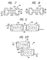
- Fig. 7 is a plan view of a strip ring resonator according to a fifth embodiment.
- a strip ring resonator 221 comprises a pair of parallel coupling line sections 222a, 222b, a C-shaped first side connecting line 223 through which first side ends of the parallel coupling line sections 222a, 222b are connected, a C-shaped second side connecting line 224 through which the other side ends of the parallel coupling line sections 222a, 222b are connected, the input tap coupling line 184, and the output tap coupling line 185.
- Each of the parallel coupling line sections 222a, 222b has a narrow width W3 and an electric length L1, and the parallel coupling line sections 222a, 222b are spaced a narrow distance S1 apart. Therefore, the parallel coupling line sections 222a, 222b are coupled to each other in inductive coupling in cases where microwaves are transmitted in the parallel coupling line sections 222a, 222b.
- a characteristic impedance in the strip loop resonator 221 is determined according to the electric length L E of the microwave resonator 225 and the inductive coupling between the parallel coupling line sections 222a, 222b.
- the strip loop resonator 221 can be minimized even though the electric length L E of the microwave resonator 225 is smaller than a wavelength of the microwaves.
- Fig. 8 is a plan view of a strip ring resonator according to a sixth embodiment.
- a strip ring resonator 231 comprises a pair of parallel coupling line sections 232a, 232b, a C-shaped first side connecting line 233 through which first side ends of the parallel coupling line sections 232a, 232b are connected, a C-shaped second side connecting line 234 through which the other side ends of the parallel coupling line sections 232a, 232b are connected, the input tap coupling line 184, and the output tap coupling line 185.
- the parallel coupling line sections 232a, 232b and the first and second side connecting lines 233, 234 respectively have a narrow width W4, so that a microwave resonator 235 having the narrow width W4 is formed of the lines 232a, 232b, 233, and 234.
- An electric length of the microwave resonator 235 is the same as that of the microwave resonator 225.
- the narrow width W4 is narrower than the width W3 of the microwave resonator 225. Therefore, the inductive coupling between the parallel coupling line sections 232a, 232b is stronger than that between the parallel coupling line sections 222a, 222b shown in Fig. 7. In contrast, capacitive coupling between the parallel coupling line sections 232a, 232b is weaker than that between the parallel coupling line sections 222a, 222b shown in Fig. 7.
- a characteristic impedance in the strip ring resonator 231 is determined according to the electric length L E of the microwave resonator 235 and the inductive coupling between the parallel coupling line sections 232a, 232b, in the same manner as in the resonator 221. Accordingly, the strip ring resonator 231 can be minimized in the same manner as the resonator 221 shown in Fig. 7.
- the line-to-line capacitor 202 be additionally provided to the resonator 221 or 222 to strengthen the capacitive coupling between the parallel coupling line sections 222a, 222b, or the parallel coupling line sections 232a, 232b. Also, it is preferred that a pair of curved coupling lines be provided in place of the straight coupling lines on condition that the curved coupling lines are spaced the distance S1 apart.
- the input and output tap coupling lines 183, 186 are respectively coupled to the first and second side connecting lines in the inductive coupling. However, it is preferred that the input and output tap coupling lines 183, 186 be coupled to the first and second side connecting lines in capacitive coupling. Also, it is preferred that the input and output tap coupling lines 183, 186 be coupled to the parallel coupling line sections 182a, 182b, to 232a, 232b.
- Fig. 9 is a plan view of a band-pass filter in which two microwave resonators 187 shown in Fig. 3 are arranged in series according to a seventh embodiment concept.
- a band-pass filter 241 comprises an input strip line 242 in which microwaves are transmitted, the microwave resonator 187 arranged in a first stage, the microwave resonator 187 arranged in a second stage, an input coupling capacitor 243 for coupling the input strip line 242 to the first-stage microwave resonator 187 in capacitive coupling, an output strip line 244 in which the microwaves resonated in the microwave resonators 187 are transmitted, an output coupling capacitor 245 for coupling the output strip line 242 to the second-stage microwave resonator 187 in capacitive coupling.
- the second side connecting line 184 of the first-stage microwave resonator 187 is coupled to the first side connecting line 183 of the second-stage microwave resonator 187 in inductive coupling. Because the width W2 of the first and second connecting lines 183, 184 is narrow, a type of the electromagnetic coupling between the first and second connecting lines 183, 184 is the inductive coupling.
- each of the microwave resonators 187 functions as a resonator and filter. Therefore, the band-pass filter 241 functions as a four-stage filter.
- the microwave resonators 187 are in rectangular shape, the microwave resonators 187 can be closely coupled to each other. Also, because a large number of rectangle-shaped microwave resonators 187 can be orderly arranged, the band-pass filter 241 can be minimized even though a large number of rectangle-shaped microwave resonators 187 are arranged in series.
- a resonance width of the microwaves in a low band is generally narrowed in cases where the microwaves are transferred in the capacitive coupling
- a resonance width of the microwaves in a high band is generally narrowed in cases where the microwaves are transferred in the inductive coupling.
- the input and output strip lines 242, 244 are coupled to the microwave resonators 187 in the capacitive coupling, and the microwave resonators 187 are coupled to each other in the inductive coupling. Therefore, the resonance width of the microwaves can be narrowed regardless of the frequency of the microwaves.
- the microwave resonators 187 are arranged in series.
- the seventh embodiment is not limited to the microwave resonators 187. That is, it is preferred that the microwave resonators 193, 213, 225, or 235 be arranged in series.
- Fig. 10 is a plan view of a band-pass filter in which two microwave resonators 187 shown in Fig. 3 are arranged in series according to an eighth embodiment.
- a band-pass filter 251 according to the seventh embodiment comprises the input tap coupling line 185, the microwave resonator 187 arranged in a first stage, the microwave resonator 187 arranged in a second stage, and the output strip line 186
- the parallel coupling line sections 182b of the first-stage microwave resonator 187 is coupled to the parallel coupling line section 182a of the second-stage microwave resonator 187 in capacitive coupling. Because the width W1 of the parallel coupling lines 182a, 182b is wide, a type of the electromagnetic coupling between the parallel coupling line sections 182a, 182b is the capacitive coupling.
- each of the microwave resonators 187 functions as a resonator and filter. Therefore, the band-pass filter 251 functions as a four-stage filter.
- the microwave resonators 187 are in rectangular shape, the microwave resonators 187 can be closely coupled to each other. Also, because a large number of rectangle-shaped microwave resonators 187 can be orderly arranged, the band-pass filter 251 can be minimized even though a large number of rectangle-shaped microwave resonators 187 are arranged in series.
- the input and output tap coupling lines 185, 186 are coupled to the microwave resonators 187 in the inductive coupling, and the microwave resonators 187 are coupled to each other in the capacitive coupling. Therefore, a resonance width of the microwaves can be narrowed regardless of the frequency of the microwaves in the band-pass filter 251.
- the microwave resonators 187 are arranged in series.
- the eighth embodiment is not limited to the microwave resonators 187. That is, it is preferred that the microwave resonators 193, 213, 225, or 235 be arranged in series.
Landscapes
- Physics & Mathematics (AREA)
- Electromagnetism (AREA)
- Control Of Motors That Do Not Use Commutators (AREA)
Claims (16)
- Streifenleitungsringresonator (181), in dem eine Mikrowelle zur Resonanz angeregt wird, mit:einer rechtwinklig geformten Ringstreifenleitung mit einer elektrischen Länge, die kürzer als eine Wellenlänge der Mikrowelle ist, zum Anregen der darin in zwei verschiedenen Richtungen zirkulierenden Mikrowelle gemäß einer Leitungsimpedanz davon zur Resonanz, wobei die rechtwinklig geformte Streifenleitung beinhaltet:ein Paar aus jeweils eine breite Breite aufweisenden parallelen Koppelleitungsabschnitten (182a, b), die kapazitiv miteinander zur Änderung einer charakteristischen Impedanz der Streifenleitung gekoppelt sind,eine erste Seitenstreifenleitung, über welche erste Seitenenden der parallelen Leitungsabschnitte (182a, b) verbunden sind, wobei die erste Seitenstreifenleitung eine schmale Breite aufweist, die schmäler als die breite Breite der parallelen Koppelleitungsabschnitte (182a, b) ist, undeine zweite Seitenstreifenleitung, über welche zweite Seitenenden der parallelen Leitungsabschnitte (182a, b) verbunden sind, wobei die zweite Seitenstreifenleitung eine weitere schmale Breite aufweist, die schmäler als die breite Breite der parallelen Koppelleitungen ist,einer mit der rechtwinklig geformten Ringstreifenleitung elektromagnetisch gekoppelten Eingangsstreifenleitung, wobei die Mikrowelle von der Eingangsstreifenleitung zu der rechtwinklig geformten Ringstreifenleitung übertragen wird, undeiner elektromagnetisch mit der rechtwinklig geformten Ringstreifenleitung gekoppelten Ausgangsstreifenleitung, wobei die Mikrowelle von der rechtwinklig geformten Streifenleitung zu der Ausgangsstreifenleitung übertragen wird.
- Resonator nach Anspruch 1, wobei die parallelen Koppelleitungsabschnitte der rechtwinklig geformten Ringstreifenleitung einander gegenüberliegende gekrümmte Innenflächen zur Verstärkung der kapazitiven Kopplung zwischen den parallelen Koppelleitungen beinhalten, wobei die gekrümmten Innenflächen um einen schmalen Abstand beabstandet sind.
- Resonator nach Anspruch 1, wobei ein sich von Leitung zu Leitung erstreckender Kondensator (Cw) mit einer konzentrierten Kapazität zwischen den parallelen Koppelleitungsabschnitten der rechtwinklig geformten Streifenleitung zur Änderung einer charakteristischen Impedanz der rechtwinklig geformten Ringstreifenleitung angeordnet ist.
- Resonator nach Anspruch 3, wobei ein Ende des sich von Leitung zu Leitung erstreckenden Kondensators (Cw) mit einem mittleren Abschnitt einer der parallelen Koppelleitungen verbunden ist und ein weiteres Ende des sich von Leitung zu Leitung erstreckenden Kondensators mit einem mittleren Abschnitt der weiteren parallelen Koppelleitung verbunden ist.
- Resonator nach Anspruch 1, wobei beide Enden der ersten und der zweiten Seitenstreifenleitung mit Innenabschnitten der parallelen Koppelleitungsabschnitte der rechtwinklig geformten Ringstreifenleitung verbunden sind, wobei die Innenabschnitte der parallelen Koppelleitungen sich einander gegenüberliegen.
- Resonator nach Anspruch 1, wobei die Eingangsstreifenleitung mit der ersten Seitenstreifenleitung über eine leitende Verbindung gekoppelt ist und die Ausgangsstreifenleitung mit der zweiten Seitenstreifenleitung über eine leitende Verbindung gekoppelt ist.
- Resonator nach Anspruch 1, wobei die Eingangsstreifenleitung mit der ersten Seitenstreifenleitung über eine induktive Verbindung gekoppelt ist und die Ausgangsstreifenleitung mit der zweiten Seitenstreifenleitung über eine induktive Verbindung gekoppelt ist.
- Streifenleitungsringresonator (221), in dem eine Mikrowelle zur Resonanz angeregt wird, mit:einer schleifenförmigen Streifenleitung mit einer elektrischen Länge, die kürzer als eine Wellenlänge der Mikrowelle ist, zum Anregen der darin in zwei verschiedenen Richtungen zirkulierenden Mikrowelle gemäß einer Leitungsimpedanz davon zur Resonanz, wobei die schleifenförmige Streifenleitung beinhaltet:ein Paar aus jeweils eine schmale Breite aufweisenden parallelen Koppelleitungsabschnitten (222a, 222b), die parallel zueinander angeordnet sind und miteinander über eine induktive Kopplung zur Änderung einer charakteristischen Impedanz der schleifenförmigen Streifenleitung gekoppelt sind,eine erste Seitenstreifenleitung (223), über welche erste Seitenenden der parallelen Leitungsabschnitte (222a, b) verbunden sind, wobei die erste Seitenstreifenleitung eine schmale Breite aufweist, undeine zweite Seitenstreifenleitung (224), über welche zweite Seitenenden der parallelen Leitungen verbunden sind, wobei die zweite Seitenstreifenleitung eine schmale Breite aufweist,einer mit der schleifenförmigen Streifenleitung elektromagnetisch gekoppelten Eingangsstreifenleitung, wobei die Mikrowelle von der Eingangsstreifenleitung zu der schleifenförmigen Streifenleitung übertragen wird, undeiner mit der schleifenförmigen Streifenleitung elektromagnetisch gekoppelten Ausgangsstreifenleitung, wobei die Mikrowelle von der schleifenförmigen Streifenleitung zu der Ausgangsstreifenleitung übertragen wird.
- Resonator nach Anspruch 8, wobei die parallelen Koppelleitungen der schleifenförmigen Streifenleitung gekrümmt sind, um einander mit einem geringen Abstand zur Verstärkung der induktiven Kopplung zwischen den parallelen Koppelleitungen gegenüber zu liegen.
- Bandpassfilter (241) zur Filterung einer Mikrowelle mit:einer Vielzahl an seriell gekoppelten rechtwinklig geformten Ringstreifenleitungen (187), von welchen eine jede ein Paar aus jeweils eine breite Breite aufweisenden parallelen Koppelleitungsabschnitten, die parallel zu einander angeordnet sind und kapazitiv miteinander zur Änderung einer charakteristischen Impedanz der rechtwinklig geformten Ringstreifenleitung gekoppelt sind, eine erste Seitenstreifenleitung mit einer schmalen Breite, über welche erste Seitenenden der parallelen Leitungen verbunden sind, und eine zweite Seitenstreifenleitung mit einer weiteren schmalen Breite beinhaltet, über welche zweite Seitenenden der parallelen Leitungen verbunden sind, wobei eine jede der rechtwinklig geformten Ringstreifenleitungen eine elektrische Länge aufweist, die kürzer als eine Wellenlänge der Mikrowelle ist, um die darin in zwei verschiedenen Richtungen zirkulierende Mikrowelle gemäß einer Leitungsimpedanz davon zur Resonanz anzuregen,einer Eingangsstreifenleitung (242), die mit der rechtwinklig geformten Streifenleitung in einer ersten Stufe gekoppelt ist, wobei die Mikrowelle von der Eingangsstreifenleitung zu der rechtwinklig geformten Streifenleitung in der ersten Stufe übertragen wird, undeiner Ausgangsstreifenleitung, die mit der rechtwinklig geformten Streifenleitung in einer letzten Stufe gekoppelt ist, wobei die Mikrowelle von der rechtwinklig geformten Streifenleitung in der letzten Stufe zu der Ausgangsstreifenleitung übertragen wird.
- Filter nach Anspruch 10, wobei eine der parallelen Koppelleitungsabschnitte der rechtwinklig geformten Ringstreifenleitung einer oberen Stufe mit einer der parallelen Koppelleitungsabschnitte der rechtwinklig geformten Ringstreifenleitung einer unteren Stufe kapazitiv gekoppelt ist.
- Filter nach Anspruch 11, wobei die Eingangs- und die Ausgangsstreifenleitung induktiv mit den rechtwinklig geformten Streifenleitungen gekoppelt sind.
- Filter nach Anspruch 10, wobei die zweite Seitenstreifenleitung der rechtwinklig geformten Streifenleitung einer oberen Stufe mit der ersten Seitenstreifenleitung der rechtwinklig geformten Streifenleitung einer unteren Stufe induktiv gekoppelt ist.
- Filter nach Anspruch 13, wobei die Eingangs- und die Ausgangsstreifenleitung mit den rechtwinklig geformten Streifenleitungen kapazitiv gekoppelt sind.
- Filter nach Anspruch 10, wobei die parallelen Koppelleitungen einer jeden der rechtwinklig geformten Streifenleitungen einander gegenüberliegende gekrümmte Innenflächen zur Verstärkung der kapazitiven Kopplung zwischen den parallelen Koppelleitungen aufweisen, wobei die gekrümmten Innenflächen mit einer geringen Distanz beabstandet sind.
- Resonator nach Anspruch 10, wobei ein von Leitung zu Leitung reichender Kondensator mit einer konzentrierten Kapazität zwischen den parallelen Koppelleitungsabschnitten eines jeden der rechtwinklig geformten Ringstreifenleitungen zur Änderung einer charakteristischen Impedanz der rechtwinklig geformten Streifenleitungen angeordnet ist.
Applications Claiming Priority (13)
| Application Number | Priority Date | Filing Date | Title |
|---|---|---|---|
| JP111127/92 | 1992-04-30 | ||
| JP11112792 | 1992-04-30 | ||
| JP11112792A JPH0637520A (ja) | 1992-04-30 | 1992-04-30 | ストリップ線路帯域通過フィルタ |
| JP11711192A JP2888027B2 (ja) | 1992-05-11 | 1992-05-11 | ストリップ線路ループ共振器フィルタ |
| JP117111/92 | 1992-05-11 | ||
| JP11711192 | 1992-05-11 | ||
| JP15323892 | 1992-06-12 | ||
| JP153238/92 | 1992-06-12 | ||
| JP4153238A JP2591402B2 (ja) | 1992-06-12 | 1992-06-12 | マイクロ波共振器及びその共振器を用いたフィルタ回路 |
| JP24437492A JP2906857B2 (ja) | 1992-09-14 | 1992-09-14 | ストリップ線路デュアル・モード・フィルタ |
| JP24437492 | 1992-09-14 | ||
| JP244374/92 | 1992-09-14 | ||
| EP93106999A EP0571777B1 (de) | 1992-04-30 | 1993-04-29 | Zweifachmodus Streifenleitungsringresonator und Bandpassfilter mit solchen Resonatoren |
Related Parent Applications (2)
| Application Number | Title | Priority Date | Filing Date |
|---|---|---|---|
| EP93106999.1 Division | 1993-04-29 | ||
| EP93106999A Division EP0571777B1 (de) | 1992-04-30 | 1993-04-29 | Zweifachmodus Streifenleitungsringresonator und Bandpassfilter mit solchen Resonatoren |
Publications (3)
| Publication Number | Publication Date |
|---|---|
| EP0730318A2 EP0730318A2 (de) | 1996-09-04 |
| EP0730318A3 EP0730318A3 (de) | 1996-09-11 |
| EP0730318B1 true EP0730318B1 (de) | 2002-08-28 |
Family
ID=27469882
Family Applications (3)
| Application Number | Title | Priority Date | Filing Date |
|---|---|---|---|
| EP96107582A Expired - Lifetime EP0731521B1 (de) | 1992-04-30 | 1993-04-29 | Zweifachmodus-Streifenleitungsringresonator und Bandpassfilter mit derartigen Resonatoren |
| EP96107583A Expired - Lifetime EP0730318B1 (de) | 1992-04-30 | 1993-04-29 | Schleifenförmiger Zweifachmodus-Streifenresonator zum Mitschwingenlassen von Mikrowellen in zwei Moden und Bandpassfilter mit den Resonatoren |
| EP93106999A Expired - Lifetime EP0571777B1 (de) | 1992-04-30 | 1993-04-29 | Zweifachmodus Streifenleitungsringresonator und Bandpassfilter mit solchen Resonatoren |
Family Applications Before (1)
| Application Number | Title | Priority Date | Filing Date |
|---|---|---|---|
| EP96107582A Expired - Lifetime EP0731521B1 (de) | 1992-04-30 | 1993-04-29 | Zweifachmodus-Streifenleitungsringresonator und Bandpassfilter mit derartigen Resonatoren |
Family Applications After (1)
| Application Number | Title | Priority Date | Filing Date |
|---|---|---|---|
| EP93106999A Expired - Lifetime EP0571777B1 (de) | 1992-04-30 | 1993-04-29 | Zweifachmodus Streifenleitungsringresonator und Bandpassfilter mit solchen Resonatoren |
Country Status (3)
| Country | Link |
|---|---|
| US (4) | US5369383A (de) |
| EP (3) | EP0731521B1 (de) |
| DE (3) | DE69319382T2 (de) |
Families Citing this family (36)
| Publication number | Priority date | Publication date | Assignee | Title |
|---|---|---|---|---|
| US5369383A (en) * | 1992-04-30 | 1994-11-29 | Matsushita Electric Industrial Co., Ltd. | Strip line filter having dual mode loop resonators |
| US5400002A (en) * | 1992-06-12 | 1995-03-21 | Matsushita Electric Industrial Co., Ltd. | Strip dual mode filter in which a resonance width of a microwave is adjusted and dual mode multistage filter in which the strip dual mode filters are arranged in series |
| JPH0856107A (ja) * | 1994-08-11 | 1996-02-27 | Matsushita Electric Ind Co Ltd | デュアルモード共振器 |
| US6239674B1 (en) * | 1993-12-27 | 2001-05-29 | Matsushita Electric Industrial Co., Ltd | Elliptical resonator with an input/output capacitive gap |
| US5587690A (en) * | 1994-08-11 | 1996-12-24 | Matsushita Electric Industrial Co., Ltd. | Ring resonator oscillator usable in frequency synthesizers and communication apparatus |
| US6653914B2 (en) * | 1994-08-31 | 2003-11-25 | Siemens Aktiengesellschaft | RF strip line resonator with a curvature dimensioned to inductively cancel capacitively caused displacements in resonant frequency |
| DE19821382A1 (de) * | 1998-05-13 | 1999-11-25 | Bosch Gmbh Robert | Verfahren zum Abgleichen der Resonanzfrequenz eines Ringresonators |
| DE19831161A1 (de) * | 1998-07-11 | 2000-01-27 | Bosch Gmbh Robert | Dual-Mode Ringresonator |
| DE19943958A1 (de) * | 1999-09-14 | 2001-03-15 | Bosch Gmbh Robert | Verfahren zum Abgleichen der Bandbreite eines Dual-Mode Filters |
| JP3395753B2 (ja) | 2000-02-24 | 2003-04-14 | 株式会社村田製作所 | バンドパスフィルタの製造方法及びバンドパスフィルタ |
| JP3395754B2 (ja) | 2000-02-24 | 2003-04-14 | 株式会社村田製作所 | デュアルモード・バンドパスフィルタ |
| JP3575378B2 (ja) * | 2000-03-13 | 2004-10-13 | 株式会社村田製作所 | デュアルモード・バンドパスフィルタの減衰極の周波数調整方法 |
| JP3587139B2 (ja) | 2000-07-12 | 2004-11-10 | 株式会社村田製作所 | デュアルモード・バンドパスフィルタ |
| JP3804481B2 (ja) | 2000-09-19 | 2006-08-02 | 株式会社村田製作所 | デュアルモード・バンドパスフィルタ、デュプレクサ及び無線通信装置 |
| US6792299B2 (en) * | 2001-03-21 | 2004-09-14 | Conductus, Inc. | Device approximating a shunt capacitor for strip-line-type circuits |
| JP3647806B2 (ja) * | 2001-12-26 | 2005-05-18 | 松下電器産業株式会社 | A/d変換器、a/d変換方法および信号処理装置 |
| JP4496516B2 (ja) * | 2002-01-31 | 2010-07-07 | ルネサスエレクトロニクス株式会社 | 高周波用配線 |
| US6617942B1 (en) * | 2002-02-15 | 2003-09-09 | Northrop Grumman Corporation | Hybrid multi-pole gain zero filter element |
| JP2004032079A (ja) * | 2002-06-21 | 2004-01-29 | Hitachi Kokusai Electric Inc | フィルタ回路およびフィルタ回路を用いた送信装置ならびに受信装置 |
| US6894584B2 (en) | 2002-08-12 | 2005-05-17 | Isco International, Inc. | Thin film resonators |
| US6825742B1 (en) | 2002-12-30 | 2004-11-30 | Raytheon Company | Apparatus and methods for split-feed coupled-ring resonator-pair elliptic-function filters |
| US20040214605A1 (en) * | 2003-04-28 | 2004-10-28 | Zhang Da Ming | Adaptable multi-band antenna system |
| TW200737586A (en) * | 2006-03-31 | 2007-10-01 | Hon Hai Prec Ind Co Ltd | Band-pass filter |
| JP2007281601A (ja) * | 2006-04-03 | 2007-10-25 | Toshiba Corp | フィルタ回路及びフィルタ回路の特性調整方法 |
| US8314740B2 (en) | 2007-09-06 | 2012-11-20 | Deka Products Limited Partnership | RFID system |
| TW200933971A (en) * | 2008-01-25 | 2009-08-01 | Univ Nat Taiwan | Filter device with transmission zero |
| US8081852B2 (en) * | 2009-01-21 | 2011-12-20 | Nanyang Technological University | Two-ring optical buffer |
| US9711833B1 (en) * | 2013-01-31 | 2017-07-18 | Physical Optics Corporation | Tunable RF anti-jamming system (TRAJS) |
| CN103107391A (zh) * | 2013-02-05 | 2013-05-15 | 南通大学 | 一种紧凑型微波分布式双模带通滤波器 |
| TWI568079B (zh) * | 2015-07-17 | 2017-01-21 | 緯創資通股份有限公司 | 天線陣列 |
| FR3043800B1 (fr) * | 2015-11-16 | 2018-09-14 | Commissariat A L'energie Atomique Et Aux Energies Alternatives | Dispositif de modulation de l'intensite d'un signal optique sur quatre niveaux differents |
| CN105963955B (zh) * | 2016-06-03 | 2017-12-26 | 江苏科技大学 | 一种高山滑雪板脱离装置 |
| RU2662058C1 (ru) * | 2017-06-26 | 2018-07-23 | Российская Федерация, от имени которой выступает Министерство обороны Российской Федерации | СВЧ-фильтр нижних частот |
| CN111477999A (zh) * | 2020-03-17 | 2020-07-31 | 北京邮电大学 | 阶梯阻抗耦合双模谐振器的ipd毫米波带通滤波器芯片 |
| CN112072238B (zh) * | 2020-07-31 | 2022-01-28 | 南京邮电大学 | 一种发夹型带通滤波器 |
| CN113745778B (zh) * | 2021-09-03 | 2022-03-29 | 合肥工业大学 | 一种双频段极化敏感带阻滤波器的制备方法 |
Family Cites Families (24)
| Publication number | Priority date | Publication date | Assignee | Title |
|---|---|---|---|---|
| US3796970A (en) * | 1973-04-04 | 1974-03-12 | Bell Telephone Labor Inc | Orthogonal resonant filter for planar transmission lines |
| US3967223A (en) * | 1974-02-19 | 1976-06-29 | Westinghouse Electric Corporation | Resonant ring transmission line having a high Q mode |
| JPS5566101A (en) * | 1978-11-13 | 1980-05-19 | Sony Corp | Microwave circuit |
| FR2460049A1 (fr) * | 1979-06-25 | 1981-01-16 | Labo Electronique Physique | Filtre coupe-bande pour ligne de transmission hyperfrequence et circuit de polarisation de transistor hyperfrequence comprenant ce filtre |
| US4371853A (en) * | 1979-10-30 | 1983-02-01 | Matsushita Electric Industrial Company, Limited | Strip-line resonator and a band pass filter having the same |
| US4327342A (en) * | 1980-07-10 | 1982-04-27 | U.S. Philips Corporation | Bandstop filter for very high frequency transmission lines and biassing circuit for a very high frequency transistor comprising this filter |
| US4488131A (en) * | 1983-02-25 | 1984-12-11 | Hughes Aircraft Company | MIC Dual mode ring resonator filter |
| JPS60244101A (ja) * | 1984-05-18 | 1985-12-04 | Hitachi Ltd | マイクロストリツプフイルタ |
| JPS60253302A (ja) * | 1984-05-30 | 1985-12-14 | Nec Corp | リング型フイルタ |
| JPS61251203A (ja) * | 1985-04-29 | 1986-11-08 | Nec Corp | トリプレ−ト形帯域濾波器 |
| JPS62298202A (ja) * | 1986-06-18 | 1987-12-25 | Matsushita Electric Ind Co Ltd | リング形共振器 |
| GB2260651B (en) * | 1988-08-04 | 1993-06-30 | Matsushita Electric Ind Co Ltd | A resonator and a filter including the same |
| SU1712988A1 (ru) * | 1989-12-12 | 1992-02-15 | Московский институт связи | Сверхвысокочастотный режекторный фильтр |
| US5313662A (en) * | 1990-07-26 | 1994-05-17 | Motorola, Inc. | Split-ring resonator bandpass filter with adjustable zero |
| US5017897A (en) * | 1990-08-06 | 1991-05-21 | Motorola, Inc. | Split ring resonator bandpass filter with differential output |
| US5136268A (en) * | 1991-04-19 | 1992-08-04 | Space Systems/Loral, Inc. | Miniature dual mode planar filters |
| US5164690A (en) * | 1991-06-24 | 1992-11-17 | Motorola, Inc. | Multi-pole split ring resonator bandpass filter |
| JPH0575316A (ja) * | 1991-09-10 | 1993-03-26 | Fujitsu Ltd | リング共振器 |
| US5172084A (en) * | 1991-12-18 | 1992-12-15 | Space Systems/Loral, Inc. | Miniature planar filters based on dual mode resonators of circular symmetry |
| JP2888027B2 (ja) * | 1992-05-11 | 1999-05-10 | 松下電器産業株式会社 | ストリップ線路ループ共振器フィルタ |
| US5369383A (en) * | 1992-04-30 | 1994-11-29 | Matsushita Electric Industrial Co., Ltd. | Strip line filter having dual mode loop resonators |
| US5400002A (en) * | 1992-06-12 | 1995-03-21 | Matsushita Electric Industrial Co., Ltd. | Strip dual mode filter in which a resonance width of a microwave is adjusted and dual mode multistage filter in which the strip dual mode filters are arranged in series |
| US5361050A (en) * | 1993-07-06 | 1994-11-01 | Motorola, Inc. | Balanced split ring resonator |
| EP0844682B1 (de) * | 1993-10-04 | 2001-06-20 | Matsushita Electric Industrial Co., Ltd. | Planares Streifenleitungsfilter und Zweimodenresonator |
-
1993
- 1993-04-29 US US08/053,535 patent/US5369383A/en not_active Expired - Lifetime
- 1993-04-29 EP EP96107582A patent/EP0731521B1/de not_active Expired - Lifetime
- 1993-04-29 DE DE69319382T patent/DE69319382T2/de not_active Expired - Fee Related
- 1993-04-29 DE DE69332250T patent/DE69332250T2/de not_active Expired - Fee Related
- 1993-04-29 EP EP96107583A patent/EP0730318B1/de not_active Expired - Lifetime
- 1993-04-29 EP EP93106999A patent/EP0571777B1/de not_active Expired - Lifetime
- 1993-04-29 DE DE69332249T patent/DE69332249T2/de not_active Expired - Fee Related
-
1994
- 1994-11-28 US US08/348,169 patent/US5497131A/en not_active Expired - Fee Related
-
1995
- 1995-10-26 US US08/548,841 patent/US5623238A/en not_active Expired - Lifetime
-
1996
- 1996-11-27 US US08/757,791 patent/US5703546A/en not_active Expired - Fee Related
Also Published As
| Publication number | Publication date |
|---|---|
| DE69332250T2 (de) | 2003-04-30 |
| EP0730318A3 (de) | 1996-09-11 |
| EP0731521A1 (de) | 1996-09-11 |
| US5369383A (en) | 1994-11-29 |
| US5703546A (en) | 1997-12-30 |
| US5623238A (en) | 1997-04-22 |
| DE69332249T2 (de) | 2003-04-10 |
| EP0571777B1 (de) | 1998-07-01 |
| EP0731521B1 (de) | 2002-08-28 |
| DE69319382D1 (de) | 1998-08-06 |
| EP0730318A2 (de) | 1996-09-04 |
| DE69332250D1 (de) | 2002-10-02 |
| DE69332249D1 (de) | 2002-10-02 |
| US5497131A (en) | 1996-03-05 |
| DE69319382T2 (de) | 1999-01-07 |
| EP0571777A1 (de) | 1993-12-01 |
Similar Documents
| Publication | Publication Date | Title |
|---|---|---|
| EP0730318B1 (de) | Schleifenförmiger Zweifachmodus-Streifenresonator zum Mitschwingenlassen von Mikrowellen in zwei Moden und Bandpassfilter mit den Resonatoren | |
| EP0573985B1 (de) | Zweifachmodus-Streifenfilter in welchem eine Resonanzbreite einer Mikrowelle eingestellt ist und mehrstufiges Zweifachmodus-Filter in welchem die Zweifachmodus-Streifenfilter seriell angeordnet sind | |
| EP0646981B1 (de) | Filter und Zweimodenresonator in Streifenleiter-Technik | |
| JP4236663B2 (ja) | 電子デバイスおよびフィルタ | |
| US20060082425A1 (en) | Microstrip type bandpass filter | |
| US6897745B2 (en) | Resonator and filter | |
| EP1926173B1 (de) | Bandpassfilter mit Dualmodus | |
| US6201458B1 (en) | Plane type strip-line filter in which strip line is shortened and mode resonator in which two types microwaves are independently resonated | |
| US7274273B2 (en) | Dielectric resonator device, dielectric filter, duplexer, and high-frequency communication apparatus | |
| US6819204B2 (en) | Bandpass filter for a radio-frequency signal and tuning method therefor | |
| JP3750420B2 (ja) | 平面フィルタおよびそれを用いたデュプレクサおよびそれらを用いた高周波モジュールおよびそれを用いた通信装置 | |
| US7457651B2 (en) | Dual mode filter based on smoothed contour resonators | |
| US5410285A (en) | Quasi-TEM mode dielectric filter | |
| US6850131B2 (en) | Bandpass filter | |
| SU1739408A1 (ru) | Режекторный СВЧ-фильтр | |
| JPH0637503A (ja) | マイクロ波共振器及びその共振器を用いたフィルタ回路 |
Legal Events
| Date | Code | Title | Description |
|---|---|---|---|
| PUAI | Public reference made under article 153(3) epc to a published international application that has entered the european phase |
Free format text: ORIGINAL CODE: 0009012 |
|
| PUAL | Search report despatched |
Free format text: ORIGINAL CODE: 0009013 |
|
| 17P | Request for examination filed |
Effective date: 19960612 |
|
| AC | Divisional application: reference to earlier application |
Ref document number: 571777 Country of ref document: EP |
|
| AK | Designated contracting states |
Kind code of ref document: A2 Designated state(s): DE FR GB |
|
| AK | Designated contracting states |
Kind code of ref document: A3 Designated state(s): DE FR GB |
|
| RIN1 | Information on inventor provided before grant (corrected) |
Inventor name: FUJIMURA, MUNENORI Inventor name: MAKIMOTO, MITSUO Inventor name: HASEGAWA, MAKOTO Inventor name: TAKAHASHI, KAZUAKI |
|
| 17Q | First examination report despatched |
Effective date: 19990426 |
|
| GRAG | Despatch of communication of intention to grant |
Free format text: ORIGINAL CODE: EPIDOS AGRA |
|
| GRAG | Despatch of communication of intention to grant |
Free format text: ORIGINAL CODE: EPIDOS AGRA |
|
| GRAG | Despatch of communication of intention to grant |
Free format text: ORIGINAL CODE: EPIDOS AGRA |
|
| GRAH | Despatch of communication of intention to grant a patent |
Free format text: ORIGINAL CODE: EPIDOS IGRA |
|
| GRAH | Despatch of communication of intention to grant a patent |
Free format text: ORIGINAL CODE: EPIDOS IGRA |
|
| GRAA | (expected) grant |
Free format text: ORIGINAL CODE: 0009210 |
|
| AC | Divisional application: reference to earlier application |
Ref document number: 571777 Country of ref document: EP |
|
| AK | Designated contracting states |
Kind code of ref document: B1 Designated state(s): DE FR GB |
|
| REG | Reference to a national code |
Ref country code: GB Ref legal event code: FG4D |
|
| REF | Corresponds to: |
Ref document number: 69332249 Country of ref document: DE Date of ref document: 20021002 |
|
| ET | Fr: translation filed | ||
| PLBE | No opposition filed within time limit |
Free format text: ORIGINAL CODE: 0009261 |
|
| STAA | Information on the status of an ep patent application or granted ep patent |
Free format text: STATUS: NO OPPOSITION FILED WITHIN TIME LIMIT |
|
| 26N | No opposition filed |
Effective date: 20030530 |
|
| PGFP | Annual fee paid to national office [announced via postgrant information from national office to epo] |
Ref country code: FR Payment date: 20090417 Year of fee payment: 17 Ref country code: DE Payment date: 20090428 Year of fee payment: 17 |
|
| PGFP | Annual fee paid to national office [announced via postgrant information from national office to epo] |
Ref country code: GB Payment date: 20090429 Year of fee payment: 17 |
|
| GBPC | Gb: european patent ceased through non-payment of renewal fee |
Effective date: 20100429 |
|
| REG | Reference to a national code |
Ref country code: FR Ref legal event code: ST Effective date: 20101230 |
|
| PG25 | Lapsed in a contracting state [announced via postgrant information from national office to epo] |
Ref country code: FR Free format text: LAPSE BECAUSE OF NON-PAYMENT OF DUE FEES Effective date: 20100430 |
|
| PG25 | Lapsed in a contracting state [announced via postgrant information from national office to epo] |
Ref country code: DE Free format text: LAPSE BECAUSE OF NON-PAYMENT OF DUE FEES Effective date: 20101103 |
|
| PG25 | Lapsed in a contracting state [announced via postgrant information from national office to epo] |
Ref country code: GB Free format text: LAPSE BECAUSE OF NON-PAYMENT OF DUE FEES Effective date: 20100429 |