EP0728984B1 - System zum Erfassen und Steuern der Schmiermittelzirkulation der Lager von Zylindern und Rollen in einer Papiermaschine - Google Patents
System zum Erfassen und Steuern der Schmiermittelzirkulation der Lager von Zylindern und Rollen in einer Papiermaschine Download PDFInfo
- Publication number
- EP0728984B1 EP0728984B1 EP19960101697 EP96101697A EP0728984B1 EP 0728984 B1 EP0728984 B1 EP 0728984B1 EP 19960101697 EP19960101697 EP 19960101697 EP 96101697 A EP96101697 A EP 96101697A EP 0728984 B1 EP0728984 B1 EP 0728984B1
- Authority
- EP
- European Patent Office
- Prior art keywords
- actuator
- lubrication
- oil
- panels
- regulation
- Prior art date
- Legal status (The legal status is an assumption and is not a legal conclusion. Google has not performed a legal analysis and makes no representation as to the accuracy of the status listed.)
- Expired - Lifetime
Links
- 238000005461 lubrication Methods 0.000 title claims abstract description 93
- 238000012544 monitoring process Methods 0.000 title claims abstract description 15
- 239000000314 lubricant Substances 0.000 claims abstract description 15
- 238000005259 measurement Methods 0.000 claims abstract description 12
- 238000012546 transfer Methods 0.000 claims description 10
- 238000000034 method Methods 0.000 claims description 7
- 238000004801 process automation Methods 0.000 claims description 3
- 230000001105 regulatory effect Effects 0.000 claims description 3
- 230000005540 biological transmission Effects 0.000 claims description 2
- 239000000126 substance Substances 0.000 claims description 2
- 230000000694 effects Effects 0.000 description 3
- 239000000463 material Substances 0.000 description 3
- 238000004891 communication Methods 0.000 description 2
- 230000007613 environmental effect Effects 0.000 description 2
- 239000004744 fabric Substances 0.000 description 2
- 238000009434 installation Methods 0.000 description 2
- 238000009529 body temperature measurement Methods 0.000 description 1
- 230000001276 controlling effect Effects 0.000 description 1
- 238000010586 diagram Methods 0.000 description 1
- 238000001035 drying Methods 0.000 description 1
- 230000008030 elimination Effects 0.000 description 1
- 238000003379 elimination reaction Methods 0.000 description 1
- 238000005516 engineering process Methods 0.000 description 1
- 238000012423 maintenance Methods 0.000 description 1
- 230000015654 memory Effects 0.000 description 1
- 238000007639 printing Methods 0.000 description 1
- 238000004886 process control Methods 0.000 description 1
- 238000012545 processing Methods 0.000 description 1
- 239000004753 textile Substances 0.000 description 1
Images


Classifications
-
- F—MECHANICAL ENGINEERING; LIGHTING; HEATING; WEAPONS; BLASTING
- F16—ENGINEERING ELEMENTS AND UNITS; GENERAL MEASURES FOR PRODUCING AND MAINTAINING EFFECTIVE FUNCTIONING OF MACHINES OR INSTALLATIONS; THERMAL INSULATION IN GENERAL
- F16N—LUBRICATING
- F16N29/00—Special means in lubricating arrangements or systems providing for the indication or detection of undesired conditions; Use of devices responsive to conditions in lubricating arrangements or systems
- F16N29/02—Special means in lubricating arrangements or systems providing for the indication or detection of undesired conditions; Use of devices responsive to conditions in lubricating arrangements or systems for influencing the supply of lubricant
-
- F—MECHANICAL ENGINEERING; LIGHTING; HEATING; WEAPONS; BLASTING
- F16—ENGINEERING ELEMENTS AND UNITS; GENERAL MEASURES FOR PRODUCING AND MAINTAINING EFFECTIVE FUNCTIONING OF MACHINES OR INSTALLATIONS; THERMAL INSULATION IN GENERAL
- F16N—LUBRICATING
- F16N7/00—Arrangements for supplying oil or unspecified lubricant from a stationary reservoir or the equivalent in or on the machine or member to be lubricated
- F16N7/38—Arrangements for supplying oil or unspecified lubricant from a stationary reservoir or the equivalent in or on the machine or member to be lubricated with a separate pump; Central lubrication systems
- F16N7/40—Arrangements for supplying oil or unspecified lubricant from a stationary reservoir or the equivalent in or on the machine or member to be lubricated with a separate pump; Central lubrication systems in a closed circulation system
-
- F—MECHANICAL ENGINEERING; LIGHTING; HEATING; WEAPONS; BLASTING
- F16—ENGINEERING ELEMENTS AND UNITS; GENERAL MEASURES FOR PRODUCING AND MAINTAINING EFFECTIVE FUNCTIONING OF MACHINES OR INSTALLATIONS; THERMAL INSULATION IN GENERAL
- F16N—LUBRICATING
- F16N2230/00—Signal processing
- F16N2230/02—Microprocessor; Microcomputer
-
- F—MECHANICAL ENGINEERING; LIGHTING; HEATING; WEAPONS; BLASTING
- F16—ENGINEERING ELEMENTS AND UNITS; GENERAL MEASURES FOR PRODUCING AND MAINTAINING EFFECTIVE FUNCTIONING OF MACHINES OR INSTALLATIONS; THERMAL INSULATION IN GENERAL
- F16N—LUBRICATING
- F16N2250/00—Measuring
- F16N2250/40—Flow
-
- Y—GENERAL TAGGING OF NEW TECHNOLOGICAL DEVELOPMENTS; GENERAL TAGGING OF CROSS-SECTIONAL TECHNOLOGIES SPANNING OVER SEVERAL SECTIONS OF THE IPC; TECHNICAL SUBJECTS COVERED BY FORMER USPC CROSS-REFERENCE ART COLLECTIONS [XRACs] AND DIGESTS
- Y10—TECHNICAL SUBJECTS COVERED BY FORMER USPC
- Y10T—TECHNICAL SUBJECTS COVERED BY FORMER US CLASSIFICATION
- Y10T137/00—Fluid handling
- Y10T137/7722—Line condition change responsive valves
- Y10T137/7758—Pilot or servo controlled
- Y10T137/7761—Electrically actuated valve
Definitions
- the invention concerns a system for control and monitoring of the circulation lubrication of the bearings of the revolving cylinders and rolls in a paper machine or equivalent, in which system lubrication oil is fed from an oil-lubrication center or centers through a system of pipes into said lubrication points, from which the lubricant is passed back through a system of return pipes into the oil-lubrication center or centers.
- a lubrication system that circulates lubrication oil is connected to the bearings of the revolving parts of a paper machine, such as cylinders and rolls.
- a paper machine typically, there are about 500 points of lubrication.
- the lubrication system has been accomplished so that oil pipes have been passed from the lubrication points spaces placed in the vicinity thereof, in which a number of oil flow meter panels have been fitted one after the other in the longitudinal direction of the paper machine. In these panels, the oil flow quantity meters and manual control members of each lubrication point, connected with the oil pipe, have been fitted.
- the oil quantities of each lubrication point are determined and set manually to be invariable. If a change in the operation values of the paper machine requires changes in the oil quantities at the lubrication points, these changes must be carried out by means of manual regulation separately from the flow meter panels of each lubrication point.
- the invention is mainly characterized in that the system comprises a number of actuator panels, which are placed and grouped in the vicinity of the lubrication points primarily above the floor level of the paper machine hall or equivalent, that from said actuator panels lubricant feed pipes are passed to a number of lubrication points placed in the vicinity, that said actuator panels comprise a feed-back connected regulation loop for lubricant flow quantity, provided for each lubrication point, which regulation loop comprises an oil-flow regulation valve, an actuator motor for same, as well as an oil-flow measurement device and a regulation circuit.
- the circulation lubrication of all the points of lubrication can be made optimal, also when the operation parameters of the paper machine are changed.
- the lubricant quantities for the different lubrication points are regulated automatically so as to be suitable for the operation parameters of the machine by for each lubrication point providing a feed-back connected regulation circuit of its own.
- the system in accordance with the invention can take into account the running values of the paper machine, such as the machine speed, the paper grade produced, the lubrication-specific parameters, such as, for example, loading and temperatures of the different bearings, the other environmental conditions, and/or properties of the lubrication oil that is used.
- the present invention can be carried into effect preferably by using the most modern electronics as well as data and control technology in its various component fields.
- the circulation oil flow-meter regulation panels of each lubrication point can be placed in groups and in the vicinity of the lubrication points. Said panels are placed and grouped so that each panel is connected with one main supply pipe for oil and with several, typically 2...8, oil supply pipes passing to the nearby lubrication points. The locations and groups of said panels are made such that the lengths of the oil pipes can be minimized or at least kept on a reasonable level. Said panels are placed above the floor level of the paper machine on the tending platform of the machine, with the exception of the panels that take care of the lubrication points of the fabrics placed underneath. The latter panels are placed in the basement spaces below the floor level of the paper machine hall.
- said actuator panels are placed both at the tending side and at the driving side of the paper machine.
- the number of these actuator panels is typically about 60...120.
- the actuator panels are connected to actuator coordinators, whose number over the length of the paper machine is typically 3...6 both at the driving side and at the tending side of the machine. These actuator coordinators are placed physically on the tending level of the machine.
- the lubrication points are usually in areas which are difficult in view of maintenance and under severe environmental conditions. Said actuator panels and actuator coordinators are chosen, dimensioned and protected so that they endure heat, vibration, moisture, and chemicals.
- the actuator panels are connected with said actuator coordinators by means of the time-share principle (multiplexing).
- the actuator coordinators communicate through a suitable communication bus with a control and display unit, which is again connected through a suitable communication bus with the rest of the process automation of the paper machine.
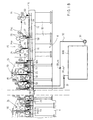
- Figure 1A is a schematic illustration of a system in accordance with the invention for monitoring and control of circulation lubrication as applied to the different lubrication points in the wet end of a paper machine.
- Figure 1B is a continuation of Fig. 1A in the machine direction, and Fig. 1B shows the dry end of the paper machine with its different lubrication points as well as the system in accordance with the invention for monitoring and control of circulation lubrication connected with said lubrication points.
- Figure 2 is a schematic illustration, partly as a block diagram, of the whole of the system in accordance with the invention for monitoring and control of circulation lubrication with the different levels of hierarchy.
- FIG. 3 illustrates one flow-meter regulation circuit in the system of monitoring and control in accordance with the invention.
- Figure 4 is a schematic illustration of a flow-meter regulator placed in the oil pipe passing into the lubrication point as well as of the connection of said flow-meter regulator with the higher system.
- Fig. 1A shows the wet end of a paper machine, which consists of a former 12 and of a press section 13. Further, Fig. 1A shows the initial end of the dryer section 14 following after the press section 13. On the other hand, Fig. 1B shows the dryer section 14, a part of whose length has been cut off, and two successive soft-calender nips 26 as the finishing device 15 after the dryer section 14, the latter one of said nips 26 being followed by the machine reel-up 16. Underneath the paper machine, there is the basement space K, in which there are vertical frames 10 both at the tending side and at the driving side of the machine, as well as horizontal frames 11 that connect said vertical frames from above. On support of said horizontal frames 11, there is the floor level of the paper machine hall and the lateral frames of the paper machine (not shown).
- the guide rolls 20 are shown as lubrication points, including the guide rolls and tensioning rolls of the various fabrics.
- Figs. 1A and 1B show the forming rolls 21 and suction rolls 22 in the former 12. By means of the latter suction roll 22, the paper web W is transferred at the pick-up point P onto the lower face of the upper press felt, which carries the web W into the first press nip N 1 .
- Fig. 1A shows the press rolls 23 in the press section 13, which rolls form successive press nips N 1 ,N 2 and N 3 , as well as the press rolls of the separate nip N 4 .
- Fig. 1B shows the steam-heated drying cylinders 24 as well as the reversing cylinders 25 between and below them, for example the applicant's VACTM rolls.
- the calender rolls 26 and the paper guide rolls 26a as well as the reeling cylinder 27 are shown.
- the main distributor pipes 34 and 35 of circulation lubricant are fitted in the machine direction of the paper machine, of which pipes the pipe 34 is the supply pipe of the lubrication oil and the pipe 35 is the return pipe of the oil.
- Said main pipes 34 and 35 communicate with the oil-lubrication centers 30A and 30B through the supply pipe 32 and the return pipe 33. From the oil-lubrication centers 30A and 30B, the lubrication oil is fed by means of the pumps 31 through the pipes 32 into the main distributor pipe 34 at the supply side, from there further by means of the distributor pipes 36 into the different actuator panels 50.
- the lubrication oil is fed to the bearings of the different lubrication points 20...27 by means of the supply pipes 38, from which points the oil returns through the return pipes 37 into the return-side main pipes 35 in the machine direction and from said pipes further through the return pipes 33 into the oil-lubrication centers 30A,30B.
- Figs. 1A and 1B there are two oil-lubrication centers 30A,30B, the first one for the wet end and the second one for the dry end of the machine. Pairs of distributor pipes 34,35 are provided both at the tending side and at the driving side of the machine, each of said pairs of pipes 34,35 communicating with the lubrication centers 30A,30B.
- Fig. 1A shows the display and control unit 70 of the control and monitoring system of circulation lubricant, which unit is connected through the first data transfer bus 73 to the actuator coordinators 40A and 40B.
- the actuator coordinators 40A,40B are connected with the data transfer buses 57 of their actuator panels 50 through the second data transfer buses 74.
- Figs. 1A and 1B just one environment of application of the invention is shown, and it should be emphasised that the invention can also be applied to many other environments of application.
- the invention can also be applied to other paper processing machines or equivalent, such as finishing machines, for example calenders, slitters, winders, and also to other machines which treat a web-like material and in which there is a great number of revolving lubrication points, and so also, for example, in textile and printing machines.
- finishing machines for example calenders, slitters, winders
- finishing machines for example calenders, slitters, winders
- finishing machines for example calenders, slitters, winders
- finishing machines for example calenders, slitters, winders
- finishing machines for example calenders, slitters, winders
- finishing machines for example calenders, slitters, winders
- finishing machines for example calenders, slitters, winders
- other machines which
- the system of control and monitoring of the circulation lubrication has been divided into three hierarchal levels, of which the highest level 70' comprises the units 70,71,72 interconnected by means of the buses a 1 ,a 2 ,a 3 . Said highest level 70' is connected through the first bus 73 with the middle actuator-coordinator level 40', which is again connected with the lower actuator level 50' by means of the second buses 74.
- the different actuator panels 50 to which several lubrication points 20...27 have been connected through the oil supply pipes 38, communicate with the actuator coordinators 40A and 40B through the data transfer bus 73, of which coordinators 40A and 40B there are, thus, two pairs, placed directly above the floor level L-L of the machine.
- the actuator coordinators 40A and 40B are connected through the first buses 73 with each other and with the control and display unit 70.
- the control and display unit 70 seeks the necessary data concerning the papermaking process, for example the running speed of the paper machine, the steam pressures, and/or equivalent.
- control and display unit 70 the set values and alarms values of the system of control and monitoring of the circulation lubrication in accordance with the invention are calculated, which values are passed to the microprocessors 42 of the actuator coordinators 40A and 40B through the buses 73.
- the control and display unit 70 the lubrication process is monitored, for example its actual values and possible alarms and equivalent.
- the control and display unit 70 transmits the set values through the bus 73 as well as reads and transfers the required data from its actuator coordinators 40A and 40B through the same bus 73.
- the bus 73 is, for example, the RS-485 bus, whose signals are denoted with the reference b 1 .
- the actuator-coordinator level 40' communicates both with the upper level 70' and with the lower actuator level 50'.
- the actuator coordinators 40A and 40B transmit the set values, the parametering values, and equivalent data to the actuator panels 50. Further, the necessary alarms are formed in the actuator coordinators 40A and 40B.
- an actuator coordinator 40 may be connected with a maximum of 48 actuators 51a,51b... (Fig. 3).
- the actuator panels 50 consist of units of two or four actuators 51a,51b... Both the actuator coordinators 40A,40B and the actuator panels 50 include data transfer buses 41 and 57, respectively, which communicate with each other through the second buses 74.
- the signals passing in the buses 74 are denoted with the references c 1 ...c n .
- a number of actuator panels 51a,51b... can be connected one after the other.
- Fig. 4 shows an exemplifying embodiment of an actuator panel 50 and of one of its actuators 51.
- the actuator group includes a connection for the lubricant intake pipe 36 for the circulation lubrication, a connection for the voltage supply 24 V DC, a connection for a serial transmission bus 57, and connections for the signals d 1 ...d n of the different actuators 51.
- the actuator 51 includes a microprocessor controller 53, which performs the control of the regulation of the lubricant flow passing to the lubrication points 20...27 through the control valve 56 of the actuator from the intake pipe 36 to the outlet pipe 38 independently.
- the actuator 51 includes a regulation circuit 52, in which there is a microprocessor 53 and a regulation control 54.
- the regulation valve 56 for the oil flow to the different lubrication points 20...27 is connected with a stepping motor 55.
- an oil quantity flow meter 57 for example an elliptic-gear meter, which gives its flow measurement signal f to the regulation control 54.
- the regulation control 54 again controls the stepping motor 55 by means of the signal g. In this way a closed regulation loop 54-g-55-56-57-f is formed, to which the set value e is given by the microprocessor 53.
- the microprocessor 53 communicates with the bus 57 through the connection d 1 and further, through the second bus 74, with its actuator coordinator 40A;40B.
- the electronic system of the regulation circuit 52 shown in Fig. 4 is capable of independently measuring the speed of rotation of the meter 57 and controlling the stepping motor 55 so that the flow is regulated and remains at the set value e given by the microprocessor 53.
- the speed of rotation of the elliptic gear or equivalent in the meter 57 is measured, for example, by means of a coil detector.
- An intelligent regulation circuit 52 is carried into effect, for example, by means of a hybrid circuit, for which all the necessary components are made, such as voltage regulation, processor 53, memories, oscillator, output stages of the stepping motor 55, coil-detector electronics, RS-485 interface circuit, and a LED that indicates rotation of the elliptic gear in the meter 57.
- Said hybrid circuit is dimensioned so that it withstands the determined conditions, such as temperature and moisture, and, moreover, it is installed on the flow meter 57 as close to the oil space 36...38 as possible, whereby the temperature of the hybrid circuit does not become higher than the temperature T 1 of the oil.
- Each of the hybrid circuit is provided with an individual serial number of its own, which number, at the same time, also operates as the device address of the serial interface. This serial number is also transferred to the meter beam, by whose means it is identified with which bearing position each of the actuators is connected.
- the actuator coordinators 40A,40B are composed, e.g., of a processor card and of one mother card.
- the processor card is a general card carried out by means of a, for example, 16-bit processor 42 and including an application program.
- the mother card operates as an interface card so that all outside cables are connected to it.
- the mother card also includes the necessary voltage regulations, the serial interfaces between the PC and actuator panels 50, the temperature measurement inputs, the digital control inputs and outputs, and, moreover, as an option, if necessary, a monitor/keyboard interface.
- the actuator coordinators 40A,40B supervise the regulation operation of the intelligent actuators 51a,51b... so that they transmit data to the detectors as to whether the measurement point concerned is in a manual or automatic position, and, moreover, when the detector notices a need of regulation, it asks the coordinator 40A;40B for permission for regulation and regulates only after it has obtained the permission.
- the power taken by the stepping motors 55 is also limited so that just one motor 55 per coordinator 40A;40B is controlled at a time with the time-share principle.
- the system of control and monitoring for circulation lubrication in accordance with the invention operates, as regards the system levels 40' and 70', with the time-share principle so that, by the intermediate of the buses 57,74, the actuator coordinators 40A,40B multiplex the set values, alarms, and the other actuator parameters for the different actuator panels 50 and, at the same time, seek the actual values of the actuators 51a,51b... from them.
- the actuator coordinator 40A;40B deals with all the actuator panels 50 connected to it and then starts a new cycle.
- the system can also be connected with measurement, alarms, and regulation based on said measurement concerning other parameters of the papermaking process and concerning the parameters of each lubrication point. This is illustrated schematically in Fig.
- the detector 58 of measurement of the temperature T 1 of the return oil which detector is fitted in connection with the oil return pipe 37 and which gives the measurement signal T 1 to the microprocessor 53 of the regulator 52 of the actuator 51.
- the detector 59 for measurement of the temperature T 2 of the lubrication point 20...27 is shown, which detector gives the measurement signal T 2 to the microprocessor 53.
Landscapes
- Engineering & Computer Science (AREA)
- General Engineering & Computer Science (AREA)
- Mechanical Engineering (AREA)
- Paper (AREA)
- Rolls And Other Rotary Bodies (AREA)
- Regulating Braking Force (AREA)
Claims (12)
- System zum Steuern und Überwachen der Zirkulationsschmierung der Lager der umlaufenden Zylinder und Walzen (20, ... ,27) bei einer Papiermaschine oder dergleichen, wobei bei dem System Schmieröl von einem Ölschmierzentrum oder von Ölschmierzentren (30A, 30B) über ein System an Leitungen (32, 34, 36) zu den Schmierstellen (20, ... , 27) zugeführt wird, von denen das Schmiermittel über ein System an Rückkehrleitungen (37, 35, 33) zu dem Ölschmierzentrum oder den Ölschmierzentren (30A, 30B) zurücktritt, wobei das System eine Anzahl an Betätigungsfeldern (50) aufweist, die in der Nähe der Schmierstellen hauptsächlich oberhalb der Fundamenthöhe (L-L) der Papiermaschinenhalle oder dergleichen angeordnet und in Gruppen vorgesehen sind, wobei von den Betätigungsfeldern (50) Schmiermittelzuführleitungen (38) zu einer Anzahl an Schmierstellen (20, ... , 27) treten, die in der Nähe angeordnet sind, wobei die Betätigungsfelder (50) eine mit einer Rückkopplung verbundene Regelschleife (52, ... , 57) für eine Schmiermittelströmungsmenge aufweisen, die für jede Schmierstelle (20, ... , 27) vorgesehen ist, wobei die Regelschleife ein Ölströmungsregelventil (56), einen Betätigungsmotor (55) für dieses und auch eine Ölströmungsmessvorrichtung (57) und eine Regelschaltung (52) aufweist.
- System gemäß Anspruch 1,
dadurch gekennzeichnet, dass
das System einen oder mehrere Betätigungskoordinator(en) (40A, 40B) aufweist, der / die mittels eines ersten Datenübertragungsbusses (73) mit einer Steuer- und Anzeigeeinheit (70) und mittels eines zweiten Datenübertragungsbusses (74) mit den Betätigungsfeldern (50) verbunden ist / sind. - System gemäß Anspruch 2,
dadurch gekennzeichnet, dass
der Betätigungskoordinator oder die Betätigungskoordinatoren (40A, 40B) ein Steuersignal (d1) und / oder die anderen Parameter zu den Reglern (51) in den Betätigungsfeldern (50) erteilt /erteilen und die tatsächlichen Werte der verschiedenen Schmierstellen (20, ... , 27) wie beispielsweise die Temperaturen (T1, T2) und / oder dergleichen empfängt /empfangen, wobei dies durch den zweiten Bus (74) geschieht, und die tatsächlichen Werte von dem Betätigungskoordinator oder den Betätigungskoordinatoren (40A, 40B) über den ersten Bus (73) zu der Steuerungs- und Anzeigeeinheit (70) übertragen werden. - System gemäß einem der Ansprüche 2 bis 3,
dadurch gekennzeichnet, dass
die Betätigungsfelder (50) und der Betätigungskoordinator oder die Betätigungskoordinatoren (40A, 40B) im Wesentlichen an oder in der Nähe der Bedienerplattform der Papiermaschine angeordnet sind und so geschützt sind, dass sie der Wärme, der Feuchtigkeit und den Chemikalien in der Umgebung widerstehen. - System gemäß einem der Ansprüche 2 bis 4,
dadurch gekennzeichnet, dass
die Anzeige- und Steuereinheit (70) über die Datenübertragungsbusse (a1, a2, a3) mit dem Prozessautomatisierungssystem (71, 72) des Papierherstellprozesses verbunden ist, wobei das System in der Regelhierarchie höher ist und wobei bei dem System die Steuerund Anzeigeeinheit (70) die Daten sucht, die für das Überwachen der Zirkulationsschmierung erforderlich sind, wie beispielsweise die Laufgeschwindigkeit der Papiermaschine, der Dampfdruck und /oder beliebige andere gleichwertige Parameter, und
in der Anzeige- und Steuereinheit (70) auf der Grundlage der Prozessdaten die eingestellten Werte und Warnwerte der Zirkulationsschmierung berechnet werden, wobei die Werte zu den Betätigungskoordinatoren (40A, 40B) über den ersten Bus (73) übertragen werden, und
mittels der Steuer- und Anzeigeeinheit (70) die tatsächlichen Werte und Warnungen des Zirkulationsschmierprozesses überwacht werden. - System gemäß einem der Ansprüche 2 bis 5,
dadurch gekennzeichnet, dass
in dem Betätigungskoordinator oder den Betätigungskoordinatoren (40A, 40B) die Warnungen des Systems erzeugt werden, und die eingestellten Werte, die Parameterwerte und / oder gleichwertige Daten zu den Betätigungsfeldern (50) übertragen werden, wobei mehrere derartige Betätigungsfelder und üblicherweise maximal 48 Felder zu einem Koordinator (40A, 40B) verbunden sind. - System gemäß einem der Ansprüche 1 bis 6,
dadurch gekennzeichnet, dass
die Betätigungsfelder (50) aus Gruppen von 2 oder 4 Betätigungsgliedern bestehen, wobei mehrere derartige Gruppen hintereinander vorzugsweise bei einem Maximum von ∼ 12 Gruppen verbunden sind, wobei die Gruppen Verbindungen für die Schmierlieferleitungen (36), für die Spannungslieferung (24 V Gleichstrom) für einen Seriell-Übertragungsbus (57) oder dergleichen und für die verschiedenen Betätigungsglieder (51a, 51b) der Betätigungsfelder (50) aufweisen, wobei durch diese Einrichtungen die Strömungsmenge des zu jeder Schmierstelle (20, ... , 27) tretenden Schmieröls geregelt wird. - System gemäß einem der Ansprüche 1 bis 7,
dadurch gekennzeichnet, dass
die Regelschaltungen (52) der Betätigungsfelder (50) eine Mikroprozessor-Steuereinrichtung (53) aufweisen, die für die Messung und Regelung der Ölströmung zu der Schmierstelle (20, ... , 27) sorgt, die mit der jeweiligen Regelschaltung unabhängig verbunden ist. - System gemäß einem der Ansprüche 1 bis 8,
dadurch gekennzeichnet, dass
der Betätigungsmotor der Betätigungsglieder (51a, 51b, ...) der Betätigungsfelder (50) ein Schrittmotor (55) ist, und der Strömungsmengenmesser (57) eine Messeinrichtung mit elliptischen Zahnrädern ist, die in Verbindung mit der Regelschaltung (52) einstückig ist, wobei die Schaltung eine Mikroprozessor-Steuereinrichtung (53) und eine Regelsteuereinrichtung (54) aufweist. - System gemäß einem der Ansprüche 1 bis 9,
dadurch gekennzeichnet, dass
das Zirkulationsschmiersystem Hauptleitungen (34, 35) der Öllieferung aufweist, die im Wesentlichen in der Maschinenrichtung in der Nähe der Fundamenthöhe (L-L) der Papiermaschine sowohl an der Bedienerseite als auch an der Antriebsseite der Maschine angeordnet sind, wobei von den Hauptleitungen die Hauptleitung (34) an der Einlassseite der Öllieferung über die Öleinlassleitung (32) mit dem Ölschmierzentrum (30A, 30B) und über die Öllieferleitungen (36) mit den Betätigungsfeldern (50) in Verbindung steht, und von den Hauptleitungen die Ölrückkehrleitung (35) mit den Schmierstellen (20, ... , 27) über die Ölrückkehrleitung (37) und mit dem Ölschmierzentrum (30A; 30B) über die Ölrückkehrleitung (33) in Verbindung steht. - System gemäß einem der Ansprüche 2 bis 10,
dadurch gekennzeichnet, dass
in Bezug auf die höheren Systemstufen (40' und 70') das System nach dem Time-sharing-Prinzip derart arbeitet, dass über die zweiten Busse (74) die Betätigungskoordinatoren (40A, 40B) die eingestellten Werte, die Warnungen und / oder die anderen Betätigungsparameter zu den mit den Koordinatoren (40A, 40B) verbundenen verschiedenen Betätigungsfeldern (50) multiplexen und die tatsächlichen Werte der Betätigungsglieder (51a, 51b, ...) von den Feldern, wie beispielsweise die Ölströmungsmengen und / oder die Temperaturwerte (T1, T2) suchen. - System gemäß Anspruch 11,
dadurch gekennzeichnet, dass
der Betätigungskoordinator (40A, 40B), der nach dem Time-sharing-Prinzip arbeitet, sämtliche Betätigungsfelder (50) handhabt, die mit ihm während eines Betriebszyklus verbunden sind, wobei danach ein neuer Betriebszyklus startet.
Applications Claiming Priority (2)
| Application Number | Priority Date | Filing Date | Title |
|---|---|---|---|
| FI950877A FI101100B (fi) | 1995-02-27 | 1995-02-27 | Paperikoneen sylinterien ja telojen laakereiden kiertovoitelun valvont a- ja ohjausjärjestelmä |
| FI950877 | 1995-02-27 |
Publications (2)
| Publication Number | Publication Date |
|---|---|
| EP0728984A1 EP0728984A1 (de) | 1996-08-28 |
| EP0728984B1 true EP0728984B1 (de) | 2002-05-15 |
Family
ID=8542930
Family Applications (1)
| Application Number | Title | Priority Date | Filing Date |
|---|---|---|---|
| EP19960101697 Expired - Lifetime EP0728984B1 (de) | 1995-02-27 | 1996-02-06 | System zum Erfassen und Steuern der Schmiermittelzirkulation der Lager von Zylindern und Rollen in einer Papiermaschine |
Country Status (8)
| Country | Link |
|---|---|
| US (1) | US5813496A (de) |
| EP (1) | EP0728984B1 (de) |
| JP (1) | JP3160523B2 (de) |
| KR (1) | KR100363456B1 (de) |
| AT (1) | ATE217698T1 (de) |
| CA (1) | CA2170446C (de) |
| DE (1) | DE69621171T2 (de) |
| FI (1) | FI101100B (de) |
Cited By (1)
| Publication number | Priority date | Publication date | Assignee | Title |
|---|---|---|---|---|
| CN102168801A (zh) * | 2011-02-18 | 2011-08-31 | 江苏巴威工程技术股份有限公司 | 稀油站 |
Families Citing this family (23)
| Publication number | Priority date | Publication date | Assignee | Title |
|---|---|---|---|---|
| KR100272677B1 (ko) * | 1998-02-02 | 2001-04-02 | 양 윤 종 | 중앙집중 관리가 가능한 윤활유 자동 공급 시스템 |
| FI105848B (fi) * | 1999-03-26 | 2000-10-13 | Valmet Corp | Menetelmä paperikoneen tai vastaavan telahydrauliikan painejärjestelmässä ja telahydrauliikan monipainejärjestelmä |
| SE9902547L (sv) * | 1999-07-02 | 2000-04-17 | Assalub Ab | Metod och anordning för manuell smörjning av ett flertal smörjpunkter |
| DE19956958A1 (de) * | 1999-11-16 | 2001-06-13 | Vogel Willi Ag | Verfahren und Vorrichtung zur Überwachung des Ölstroms einer Einrichtung zur Öl+Luft-Schmierung von Bauteilen |
| NL1014210C2 (nl) * | 2000-01-27 | 2001-07-30 | Skf Eng & Res Centre Bv | Intelligent lageronderhoud. |
| US7185537B2 (en) * | 2003-06-04 | 2007-03-06 | Metso Paper, Inc. | Nip and loading analysis system |
| FI123370B (fi) | 2007-11-07 | 2013-03-15 | Metso Paper Inc | Menetelmä kiertovoitelun ohjaamiseksi ja kiertovoitelujärjestelmä |
| CN101561076B (zh) * | 2009-03-09 | 2011-04-20 | 职子竖 | 润滑剂分配系统监控方法及采用该方法的润滑剂分配系统 |
| WO2011025430A1 (en) * | 2009-08-27 | 2011-03-03 | Aktiebolaget Skf | A method and a system for establishing and executing correct automatic relubrication for a number of bearings |
| JP5917486B2 (ja) * | 2010-04-01 | 2016-05-18 | アクティエボラゲット・エスコーエッフ | 潤滑システムおよび潤滑剤の供給手段ならびにさらに潤滑システムのためのコンピュータ化された制御手段さらには潤滑システムによって潤滑を行うための方法 |
| US9140407B2 (en) | 2010-11-29 | 2015-09-22 | Lincoln Industrial Corporation | Pump having stirrer and direct feed |
| CA2846654C (en) | 2011-08-30 | 2019-05-28 | Stephania Holdings Inc. | Methods of controlling a lubricator apparatus, methods of communication, and apparatuses and systems |
| DE102012218443A1 (de) | 2012-06-26 | 2014-01-02 | Skf Lubrication Systems Germany Ag | Verfahren zum Betreiben eines Zentralschmiersystems und Zentralschmiersystem |
| US9904296B2 (en) * | 2014-04-01 | 2018-02-27 | Honeywell International Inc. | Controlling flow in a fluid distribution system |
| US9551460B2 (en) | 2014-12-23 | 2017-01-24 | Lincoln Industrial Corporation | Bearing system with lubrication controller |
| US9695979B2 (en) | 2014-12-23 | 2017-07-04 | Lincoln Industrial Corporation | Method of controlling bearing lubrication system |
| US9841141B2 (en) | 2014-12-31 | 2017-12-12 | Lincoln Industrial Corporation | Lubrication method for housing having an exclusion seal |
| US9810372B2 (en) | 2014-12-31 | 2017-11-07 | Lincoln Industrial Coporation | Bearing system with lubricated exclusion seal |
| EP3056790B1 (de) * | 2015-02-11 | 2019-04-03 | O.M.C.A. di Bassi Giovanni | Zentral schmierungssystem für eine mechanische vorrichtung |
| US12142105B2 (en) | 2017-08-04 | 2024-11-12 | Skf Canada Limited | Interchangeable control module for fixed and portable lubricant dispensing devices |
| US12188612B2 (en) * | 2017-08-04 | 2025-01-07 | Skf Canada Limited | Interchangeable control module for fixed and portable lubricant dispensing devices |
| US12007360B2 (en) * | 2020-12-22 | 2024-06-11 | U.E. Systems, Inc. | Globally-based automatic lubrication system |
| CA221424S (en) | 2023-05-12 | 2024-08-13 | A T S Electro Lube Int Inc | Lubricant applicator |
Family Cites Families (14)
| Publication number | Priority date | Publication date | Assignee | Title |
|---|---|---|---|---|
| US1769007A (en) * | 1927-08-27 | 1930-07-01 | Wiltse Appliance Co | Pump mechanism |
| DE2016316A1 (de) * | 1970-04-06 | 1971-10-28 | Joseph Vögele AG, 6800 Mannheim | Einrichtung zur Regelung und gleichzeitigen Überwachung des Schmiermittelflusses in Schmieranlagen, insbes. Fettschmieranlagen |
| DE2028944C3 (de) * | 1970-06-12 | 1974-11-28 | Walter Dr.-Ing. 7531 Tiefenbronn Klaschka | Vorrichtung zum Überwachen der Schmiermittelversorgung in einer Zentralschmieranlage |
| DE2229990A1 (de) * | 1972-06-20 | 1974-01-10 | Walter Dr Ing Klaschka | Schmiersystem |
| DE2929580A1 (de) * | 1979-07-21 | 1981-02-05 | Mm A N Maschinenfabrik Augsbur | Schmiersystem fuer eine brennkraftmaschine |
| US4614300A (en) * | 1982-04-19 | 1986-09-30 | E. I. Du Pont De Nemours And Company | Computerized spray machine |
| FI65661B (fi) * | 1982-07-28 | 1984-02-29 | O Kytole Ja Kumpp Ky | Foerfarande och anordning foer smoerjning av lager vid en apparat innefattande flera oljesmorda lager |
| JPH0758967B2 (ja) * | 1986-02-10 | 1995-06-21 | 株式会社トキメック | 流体制御弁の通信制御システム |
| US5297260A (en) * | 1986-03-12 | 1994-03-22 | Hitachi, Ltd. | Processor having a plurality of CPUS with one CPU being normally connected to common bus |
| FR2647182B1 (fr) * | 1989-05-22 | 1992-01-10 | Cit Alcatel | Dispositif pour l'alimentation en graisse de plusieurs paliers |
| US5029672A (en) * | 1989-10-13 | 1991-07-09 | Am International | Lubricating system for printing, duplicating and like machines |
| DE69230428T2 (de) * | 1991-09-27 | 2000-08-03 | Sun Microsystems, Inc. | Verklemmungserkennung und Maskierung enthaltende Busarbitrierungsarchitektur |
| US5190068A (en) * | 1992-07-02 | 1993-03-02 | Brian Philbin | Control apparatus and method for controlling fluid flows and pressures |
| WO1994007045A1 (en) * | 1992-09-11 | 1994-03-31 | Hanes Charles E | Stiff bearing system with minimal vibration characteristics |
-
1995
- 1995-02-27 FI FI950877A patent/FI101100B/fi active IP Right Grant
-
1996
- 1996-02-06 EP EP19960101697 patent/EP0728984B1/de not_active Expired - Lifetime
- 1996-02-06 DE DE69621171T patent/DE69621171T2/de not_active Expired - Fee Related
- 1996-02-06 AT AT96101697T patent/ATE217698T1/de not_active IP Right Cessation
- 1996-02-27 KR KR1019960004849A patent/KR100363456B1/ko not_active Expired - Fee Related
- 1996-02-27 US US08/607,853 patent/US5813496A/en not_active Expired - Fee Related
- 1996-02-27 CA CA 2170446 patent/CA2170446C/en not_active Expired - Fee Related
- 1996-02-27 JP JP6392396A patent/JP3160523B2/ja not_active Expired - Fee Related
Cited By (1)
| Publication number | Priority date | Publication date | Assignee | Title |
|---|---|---|---|---|
| CN102168801A (zh) * | 2011-02-18 | 2011-08-31 | 江苏巴威工程技术股份有限公司 | 稀油站 |
Also Published As
| Publication number | Publication date |
|---|---|
| JPH08247386A (ja) | 1996-09-27 |
| DE69621171D1 (de) | 2002-06-20 |
| DE69621171T2 (de) | 2002-10-02 |
| EP0728984A1 (de) | 1996-08-28 |
| FI101100B (fi) | 1998-04-15 |
| KR100363456B1 (ko) | 2003-02-17 |
| FI950877A0 (fi) | 1995-02-27 |
| CA2170446A1 (en) | 1996-08-28 |
| ATE217698T1 (de) | 2002-06-15 |
| CA2170446C (en) | 2006-08-22 |
| JP3160523B2 (ja) | 2001-04-25 |
| US5813496A (en) | 1998-09-29 |
| FI950877A7 (fi) | 1996-08-28 |
Similar Documents
| Publication | Publication Date | Title |
|---|---|---|
| EP0728984B1 (de) | System zum Erfassen und Steuern der Schmiermittelzirkulation der Lager von Zylindern und Rollen in einer Papiermaschine | |
| US5825653A (en) | Method for overall regulation of a former of a paper machine or equivalent | |
| US5381341A (en) | Control system for a paper or board machine | |
| US5649448A (en) | System for overall control of different transverse profiles in a paper web manufactured in a board of paper machine and/or treated in a finishing machine | |
| US4314878A (en) | Method of operating a papermachine drying line | |
| US4374703A (en) | Control system for papermaking machine headbox | |
| US5812404A (en) | Method for overall regulation of the headbox of a paper machine or equivalent | |
| US6521089B1 (en) | Process for controlling or regulating the basis weight of a paper or cardboard web | |
| FI76872B (fi) | Foerfarande och anordning foer styrning av zonvals. | |
| US3547775A (en) | Means and method for modulating fiber stock flow in papermaking headbox in response to paper sheet product parameters | |
| AU2006208249A1 (en) | System and method to control press section dewatering on paper and pulp drying machines using chemical dewatering agents | |
| US6094604A (en) | Coordinated control of sheet properties by receiving a measured and broadcasted properties data, determining a control action, and broadcasting a predicted changes to other actuators | |
| US5603806A (en) | Method and apparatus for lateral alignment of the cross-direction quality profile of a web in a paper machine | |
| CA2282751A1 (en) | Regulation system in a paper machine for controlling variation of the basis weight of the paper in the machine direction | |
| EP1196654A1 (de) | Verfahren und vorrichtung zur steuerung einer bewegten papierbahn | |
| EP0837966B1 (de) | Verfahren zur stauffauflauf- und/oder formergesamtregelung einer papiermaschine oder dergleichen | |
| US6993408B2 (en) | Method for the control of quality in a paper web | |
| US2810940A (en) | Paper manufacture | |
| FI91899C (fi) | Paperikoneen kuivatusosan alapuolinen tilajärjestely | |
| US3077924A (en) | Paper making system | |
| US6248213B1 (en) | Procedure for washing the fabrics of a paper machine or equivalent | |
| CA1203407A (en) | System for washing pulp | |
| Karlsson et al. | Controllability of paper making | |
| WO2000079042A1 (en) | Method and arrangement for positioning a shoe of a shoe press/shoe calender in a paper machine | |
| EP1155191A1 (de) | Verfahren zur qualitätsveränderung auf einer papiermaschine |
Legal Events
| Date | Code | Title | Description |
|---|---|---|---|
| PUAI | Public reference made under article 153(3) epc to a published international application that has entered the european phase |
Free format text: ORIGINAL CODE: 0009012 |
|
| AK | Designated contracting states |
Kind code of ref document: A1 Designated state(s): AT DE FR GB IT SE |
|
| 17P | Request for examination filed |
Effective date: 19960925 |
|
| 17Q | First examination report despatched |
Effective date: 19990430 |
|
| GRAG | Despatch of communication of intention to grant |
Free format text: ORIGINAL CODE: EPIDOS AGRA |
|
| RAP1 | Party data changed (applicant data changed or rights of an application transferred) |
Owner name: METSO PAPER, INC. |
|
| GRAG | Despatch of communication of intention to grant |
Free format text: ORIGINAL CODE: EPIDOS AGRA |
|
| GRAH | Despatch of communication of intention to grant a patent |
Free format text: ORIGINAL CODE: EPIDOS IGRA |
|
| GRAH | Despatch of communication of intention to grant a patent |
Free format text: ORIGINAL CODE: EPIDOS IGRA |
|
| GRAA | (expected) grant |
Free format text: ORIGINAL CODE: 0009210 |
|
| AK | Designated contracting states |
Kind code of ref document: B1 Designated state(s): AT DE FR GB IT SE |
|
| PG25 | Lapsed in a contracting state [announced via postgrant information from national office to epo] |
Ref country code: IT Free format text: LAPSE BECAUSE OF FAILURE TO SUBMIT A TRANSLATION OF THE DESCRIPTION OR TO PAY THE FEE WITHIN THE PRESCRIBED TIME-LIMIT;WARNING: LAPSES OF ITALIAN PATENTS WITH EFFECTIVE DATE BEFORE 2007 MAY HAVE OCCURRED AT ANY TIME BEFORE 2007. THE CORRECT EFFECTIVE DATE MAY BE DIFFERENT FROM THE ONE RECORDED. Effective date: 20020515 Ref country code: FR Free format text: LAPSE BECAUSE OF FAILURE TO SUBMIT A TRANSLATION OF THE DESCRIPTION OR TO PAY THE FEE WITHIN THE PRESCRIBED TIME-LIMIT Effective date: 20020515 |
|
| REF | Corresponds to: |
Ref document number: 217698 Country of ref document: AT Date of ref document: 20020615 Kind code of ref document: T |
|
| REG | Reference to a national code |
Ref country code: GB Ref legal event code: FG4D |
|
| REF | Corresponds to: |
Ref document number: 69621171 Country of ref document: DE Date of ref document: 20020620 |
|
| PG25 | Lapsed in a contracting state [announced via postgrant information from national office to epo] |
Ref country code: SE Free format text: LAPSE BECAUSE OF FAILURE TO SUBMIT A TRANSLATION OF THE DESCRIPTION OR TO PAY THE FEE WITHIN THE PRESCRIBED TIME-LIMIT Effective date: 20020815 |
|
| EN | Fr: translation not filed | ||
| PLBE | No opposition filed within time limit |
Free format text: ORIGINAL CODE: 0009261 |
|
| STAA | Information on the status of an ep patent application or granted ep patent |
Free format text: STATUS: NO OPPOSITION FILED WITHIN TIME LIMIT |
|
| 26N | No opposition filed |
Effective date: 20030218 |
|
| PGFP | Annual fee paid to national office [announced via postgrant information from national office to epo] |
Ref country code: DE Payment date: 20080219 Year of fee payment: 13 Ref country code: GB Payment date: 20080220 Year of fee payment: 13 |
|
| PGFP | Annual fee paid to national office [announced via postgrant information from national office to epo] |
Ref country code: AT Payment date: 20080215 Year of fee payment: 13 |
|
| GBPC | Gb: european patent ceased through non-payment of renewal fee |
Effective date: 20090206 |
|
| PG25 | Lapsed in a contracting state [announced via postgrant information from national office to epo] |
Ref country code: AT Free format text: LAPSE BECAUSE OF NON-PAYMENT OF DUE FEES Effective date: 20090206 |
|
| PG25 | Lapsed in a contracting state [announced via postgrant information from national office to epo] |
Ref country code: DE Free format text: LAPSE BECAUSE OF NON-PAYMENT OF DUE FEES Effective date: 20090901 |
|
| PG25 | Lapsed in a contracting state [announced via postgrant information from national office to epo] |
Ref country code: GB Free format text: LAPSE BECAUSE OF NON-PAYMENT OF DUE FEES Effective date: 20090206 |