EP0726806B1 - Procede de fabrication d'une poudre dans un jet de plasma et dispositif permettant de mettre en ouvre ledit procede - Google Patents
Procede de fabrication d'une poudre dans un jet de plasma et dispositif permettant de mettre en ouvre ledit procede Download PDFInfo
- Publication number
- EP0726806B1 EP0726806B1 EP95932003A EP95932003A EP0726806B1 EP 0726806 B1 EP0726806 B1 EP 0726806B1 EP 95932003 A EP95932003 A EP 95932003A EP 95932003 A EP95932003 A EP 95932003A EP 0726806 B1 EP0726806 B1 EP 0726806B1
- Authority
- EP
- European Patent Office
- Prior art keywords
- plasma
- plasma chamber
- plasma arc
- reaction partner
- reaction
- Prior art date
- Legal status (The legal status is an assumption and is not a legal conclusion. Google has not performed a legal analysis and makes no representation as to the accuracy of the status listed.)
- Expired - Lifetime
Links
- 238000000034 method Methods 0.000 title claims description 23
- 239000000843 powder Substances 0.000 title claims description 20
- 238000006243 chemical reaction Methods 0.000 claims description 31
- 239000007789 gas Substances 0.000 claims description 16
- 238000002156 mixing Methods 0.000 claims description 8
- 238000010924 continuous production Methods 0.000 claims description 5
- 229910052738 indium Inorganic materials 0.000 claims description 4
- QVGXLLKOCUKJST-UHFFFAOYSA-N atomic oxygen Chemical compound [O] QVGXLLKOCUKJST-UHFFFAOYSA-N 0.000 claims description 3
- APFVFJFRJDLVQX-UHFFFAOYSA-N indium atom Chemical compound [In] APFVFJFRJDLVQX-UHFFFAOYSA-N 0.000 claims description 3
- 239000000155 melt Substances 0.000 claims description 3
- 229910052760 oxygen Inorganic materials 0.000 claims description 3
- 239000001301 oxygen Substances 0.000 claims description 3
- ATJFFYVFTNAWJD-UHFFFAOYSA-N Tin Chemical compound [Sn] ATJFFYVFTNAWJD-UHFFFAOYSA-N 0.000 claims description 2
- 230000015572 biosynthetic process Effects 0.000 claims 1
- 210000002381 plasma Anatomy 0.000 description 98
- 239000002184 metal Substances 0.000 description 13
- 229910052751 metal Inorganic materials 0.000 description 13
- 239000000376 reactant Substances 0.000 description 12
- OKTJSMMVPCPJKN-UHFFFAOYSA-N Carbon Chemical compound [C] OKTJSMMVPCPJKN-UHFFFAOYSA-N 0.000 description 5
- 239000000919 ceramic Substances 0.000 description 5
- 238000004519 manufacturing process Methods 0.000 description 5
- XEEYBQQBJWHFJM-UHFFFAOYSA-N Iron Chemical compound [Fe] XEEYBQQBJWHFJM-UHFFFAOYSA-N 0.000 description 4
- 229910052799 carbon Inorganic materials 0.000 description 4
- 230000006698 induction Effects 0.000 description 4
- 239000007858 starting material Substances 0.000 description 4
- 150000002739 metals Chemical class 0.000 description 3
- VNWKTOKETHGBQD-UHFFFAOYSA-N methane Chemical compound C VNWKTOKETHGBQD-UHFFFAOYSA-N 0.000 description 3
- 239000007787 solid Substances 0.000 description 3
- 229910052718 tin Inorganic materials 0.000 description 3
- 239000007795 chemical reaction product Substances 0.000 description 2
- 150000001875 compounds Chemical class 0.000 description 2
- 229910052802 copper Inorganic materials 0.000 description 2
- 239000013078 crystal Substances 0.000 description 2
- 230000007423 decrease Effects 0.000 description 2
- 238000009826 distribution Methods 0.000 description 2
- 239000012530 fluid Substances 0.000 description 2
- 239000008187 granular material Substances 0.000 description 2
- 229910003437 indium oxide Inorganic materials 0.000 description 2
- 229910052742 iron Inorganic materials 0.000 description 2
- 229910052745 lead Inorganic materials 0.000 description 2
- HTUMBQDCCIXGCV-UHFFFAOYSA-N lead oxide Chemical compound [O-2].[Pb+2] HTUMBQDCCIXGCV-UHFFFAOYSA-N 0.000 description 2
- 239000007788 liquid Substances 0.000 description 2
- 229910001507 metal halide Inorganic materials 0.000 description 2
- 150000005309 metal halides Chemical class 0.000 description 2
- 229910052709 silver Inorganic materials 0.000 description 2
- XOLBLPGZBRYERU-UHFFFAOYSA-N tin dioxide Chemical compound O=[Sn]=O XOLBLPGZBRYERU-UHFFFAOYSA-N 0.000 description 2
- 229910001887 tin oxide Inorganic materials 0.000 description 2
- 229910052725 zinc Inorganic materials 0.000 description 2
- 229910004298 SiO 2 Inorganic materials 0.000 description 1
- 238000005299 abrasion Methods 0.000 description 1
- 239000010405 anode material Substances 0.000 description 1
- 238000013459 approach Methods 0.000 description 1
- 239000011195 cermet Substances 0.000 description 1
- 239000003245 coal Substances 0.000 description 1
- 238000000576 coating method Methods 0.000 description 1
- 238000012790 confirmation Methods 0.000 description 1
- 238000013461 design Methods 0.000 description 1
- 238000002474 experimental method Methods 0.000 description 1
- 230000002349 favourable effect Effects 0.000 description 1
- 239000010439 graphite Substances 0.000 description 1
- 229910002804 graphite Inorganic materials 0.000 description 1
- 230000005484 gravity Effects 0.000 description 1
- 229910052736 halogen Inorganic materials 0.000 description 1
- 150000002367 halogens Chemical class 0.000 description 1
- PJXISJQVUVHSOJ-UHFFFAOYSA-N indium(iii) oxide Chemical compound [O-2].[O-2].[O-2].[In+3].[In+3] PJXISJQVUVHSOJ-UHFFFAOYSA-N 0.000 description 1
- 230000000977 initiatory effect Effects 0.000 description 1
- 238000002347 injection Methods 0.000 description 1
- 239000007924 injection Substances 0.000 description 1
- 229910052500 inorganic mineral Inorganic materials 0.000 description 1
- 229910000464 lead oxide Inorganic materials 0.000 description 1
- 229910001338 liquidmetal Inorganic materials 0.000 description 1
- 239000000463 material Substances 0.000 description 1
- 229910044991 metal oxide Inorganic materials 0.000 description 1
- 150000004706 metal oxides Chemical class 0.000 description 1
- 238000005272 metallurgy Methods 0.000 description 1
- 239000011707 mineral Substances 0.000 description 1
- 239000000203 mixture Substances 0.000 description 1
- 230000003647 oxidation Effects 0.000 description 1
- 238000007254 oxidation reaction Methods 0.000 description 1
- 230000001590 oxidative effect Effects 0.000 description 1
- YEXPOXQUZXUXJW-UHFFFAOYSA-N oxolead Chemical compound [Pb]=O YEXPOXQUZXUXJW-UHFFFAOYSA-N 0.000 description 1
- 239000010453 quartz Substances 0.000 description 1
- 238000011160 research Methods 0.000 description 1
- VYPSYNLAJGMNEJ-UHFFFAOYSA-N silicon dioxide Inorganic materials O=[Si]=O VYPSYNLAJGMNEJ-UHFFFAOYSA-N 0.000 description 1
- 239000007921 spray Substances 0.000 description 1
- 230000006641 stabilisation Effects 0.000 description 1
- 238000011105 stabilization Methods 0.000 description 1
- 238000012549 training Methods 0.000 description 1
- 239000002699 waste material Substances 0.000 description 1
Images


Classifications
-
- B—PERFORMING OPERATIONS; TRANSPORTING
- B01—PHYSICAL OR CHEMICAL PROCESSES OR APPARATUS IN GENERAL
- B01J—CHEMICAL OR PHYSICAL PROCESSES, e.g. CATALYSIS OR COLLOID CHEMISTRY; THEIR RELEVANT APPARATUS
- B01J19/00—Chemical, physical or physico-chemical processes in general; Their relevant apparatus
- B01J19/08—Processes employing the direct application of electric or wave energy, or particle radiation; Apparatus therefor
- B01J19/087—Processes employing the direct application of electric or wave energy, or particle radiation; Apparatus therefor employing electric or magnetic energy
- B01J19/088—Processes employing the direct application of electric or wave energy, or particle radiation; Apparatus therefor employing electric or magnetic energy giving rise to electric discharges
-
- C—CHEMISTRY; METALLURGY
- C01—INORGANIC CHEMISTRY
- C01G—COMPOUNDS CONTAINING METALS NOT COVERED BY SUBCLASSES C01D OR C01F
- C01G15/00—Compounds of gallium, indium or thallium
-
- C—CHEMISTRY; METALLURGY
- C01—INORGANIC CHEMISTRY
- C01G—COMPOUNDS CONTAINING METALS NOT COVERED BY SUBCLASSES C01D OR C01F
- C01G19/00—Compounds of tin
- C01G19/02—Oxides
Definitions
- the invention relates to a method for the continuous production of a powder by the Reaction of at least two reactants in a plasma arc, in which a first and a second reaction partner can be supplied to the plasma arc, which by means of an intermediate a first and a second electrode applied voltage is maintained, wherein at least the first reaction partner is electrically conductive and used as the first electrode becomes.
- the invention further relates to a device for the continuous production of a powder by reaction of at least a first and a second reaction partner in a plasma arc, with a feed device for the feed of at least the first reactant to a filling opening of a plasma chamber, which is directed towards one of the filling opening has opposite passage tapered interior, and with at least two electrodes connected to a generator to maintain a plasma arc in the plasma chamber, the first electrode being formed by the first reaction partner.
- the plasma is a complex medium that can be obtained at very high temperatures of, for example, 3000 ° C. It is very reactive, so the chemical reactions take place at high speed.
- Plasma is formed by the ionization of a gas through electrical discharge of direct current, with high-frequency discharge and with microwave discharge. Examples of current use are: reduction of iron ore by injecting iron ore (oxide) and coal into a plasma torch; by injecting numerous metal oxides Cr 2 O 3 , SiO 2 , CaO, MgO ...
- Plasma arcs are used primarily in metallurgy at high temperatures above 1500 ° C used. They consume large amounts of electrical energy. You need electrodes that accumulate as waste after use and are therefore polluting to the environment.
- An induction plasma can also be generated without electrodes, but its performance is weaker, as in the document "Les Plasmas Industriels” of the French ministry for teaching, research and higher education - La Documentation civile, no. 10, 1986 -).
- a method and a device according to the type specified are from the Swiss Patent CH 281 749 known. It describes a process for the production of metal halides described, one of a mixture of minerals of the corresponding Metals and carbon anode is made between this anode and one Carbon cathode creates an arc in a halogen-containing atmosphere and so the metal halide is formed.
- a device according to the type specified is from the British patent GB 959,027 known.
- the plasma spray device described there has a plasma chamber and a feed device for feeding a metallic as an electrode Wire into the plasma chamber.
- the feed device has an outlet on its underside for the wire, which is coaxial to the upward, towards the feeder, open interior of the plasma chamber runs.
- the interior of the plasma chamber narrows downwards tapered towards an outlet nozzle.
- the present invention is therefore based on the one hand the task of a simple and inexpensive Process for the continuous and reproducible production of a powder by specify the reaction of at least two reactants in a plasma arc and one To provide device for this, which is a homogeneous and uniform plasma and thus reproducible results guaranteed.
- this object is achieved in that the first Reactant is supplied to the plasma arc in molten form, the Plasma arc in a substantially parabolic interior of a plasma chamber is maintained.
- the first reactant is in the form of a melt. It is not necessary to have one to produce the first reactant-containing solid electrode. Signs of wear or soiling due to abrasion, as observed, for example, with an induction plasma are therefore not to be feared.
- the supply of the first reaction partner to the For example, plasma arcing can take advantage of gravity due to its own Weight based by a stream of a material containing the first reactant the plasma arc is fed from above. Because the first reactant A homogeneous distribution can also be supplied to the plasma arc in fluid form easily reach the reactant within such a stream.
- the second reaction partner can also in fluid form, for example as a gas, the plasma arc be fed. This creates a particularly stable and homogeneous plasma receive.
- the first reaction partner is advantageously an electrode with a negative potential switched.
- this is advantageously provided with an energy that the free enthalpy of education from the Reactive partner to produce chemical compound plus the heat loss in the Plasma arc corresponds.
- a particularly stable plasma is obtained when the plasma arc is in a plasma chamber with a parabolic interior seen in cross section, which with a Filling opening for the first reactant and with one opposite the filling opening Passage is maintained. About the passage that is in the plasma arc formed reaction product released from the plasma chamber.
- the interior has essentially the shape of a paraboloid.
- the plasma chamber has at least the first reaction partner is fed in a beam, the long axis of the parabolic interior the plasma chamber is coaxial with the beam.
- the plasma arc is advantageously ignited in one of the centers of the parabola.
- the The center of the parabola should be the one closest to the passage of the plasma chamber lies. This results in a particularly stable plasma.
- a particularly stable plasma is obtained when the passage through the plasma chamber is extended on the outside with a mixing tube, a negative pressure is maintained at the outlet opening becomes.
- the mixing tube can act as a so-called "Venturi nozzle”.
- the negative pressure is advantageously generated by means of a supersonic nozzle adjoining the mixing tube maintain.
- a process in which a melt is the first reaction partner has proven particularly useful of indium and tin, and an oxidizing gas is used as the second reaction partner.
- the above-mentioned task is based on the above-mentioned Device according to the invention solved in that the feed device a vessel for includes the reception of the first reactant, which at its the filling opening of the plasma chamber facing bottom is provided with an outlet in the direction of the substantially parabolic interior of the plasma chamber is directed.
- the first reaction partner becomes the plasma arc in the molten liquid Form fed.
- Interior of the plasma chamber is a both in terms of local fixation, its geometric training as well as a particularly stable plasma arc in terms of its energy enables. Apart from discontinuities, for example in the upper or lower area the interior forms a paraboloid.
- Figure 1 illustrates the principle of the reduction of an ore by a plasma arc.
- the burner 1 and the electrode 2 are fed by the direct current generated by a generator 3.
- the plasma gas 4 is supplied to the burner while an external gas 7 is introduced or extracted.
- the oxide 5 or the components are fed to the plasma arc 9 through a funnel 8.
- the powdery compound formed in the plasma arc 9 is in a container 6 caught.
- FIG. 2 illustrates a further customary method for producing a powder in a plasma arc, in which case a starting powder 10 is injected into the flame 11 of a burner 13 by means of an atomizer 11. It can be seen from the illustration that the powder produced in this way cannot be very homogeneous.
- FIG. 3 illustrates the principle of the induction plasma.
- a gas 15 is introduced into a quartz tube 14, which is ionized within a high-frequency coil 19 by a high-energy beam 16 at high speed and in this way generates the plasma 17 in which the desired reaction product 18 is generated.
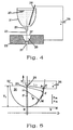
- FIG. 4 illustrates the method according to the invention using an example.
- Liquid metal 20 is located in a crucible 21.
- the molten metal 20 thus forms the negatively charged electrode of the device.
- the crucible 21 is provided on its underside with a calibrated ceramic nozzle 22 from which the molten metal 20 emerges in a jet 23.
- the electrically negatively charged beam 23 flows via the filling opening 37 of the plasma chamber 28 at the oppositely charged electrode 25 over, which is connected to the opposite pole of the voltage source 26.
- the plasma chamber 28 is formed inside the electrode 25.
- other reactants are also introduced, which are within the metal melt 20 of the plasma arc react to the desired powder.
- the procedure is self-evident also for the use of other known devices and methods for plasma generation, such as the use of high frequency current.
- a special feature of the invention is that the plasma is closed in one place the structure of which is firm and stable.
- the starting material whether it is made of a solid body, from granules or consists of powder, distributed within the jet of ionized gas or plasma, which exits the burner at high speed.
- the initiation and dwell time of the The starting material in the plasma is short and random.
- the jet 23 of starting material is directed into a plasma chamber 28 designed in the manner of a paraboloid.
- This chamber 28 has a shape optimized for a given pressure or plasma gas. It goes down into a mixing nozzle 27 which comprises an interior which widens conically outwards. The distance between the jet 23 and the inner wall of the chamber 28 initially varies slowly and decreases faster and faster as the jet 23 moves downward.
- the most favorable shape of the interior of the chamber 28, which is shown in Figure 5 was found by calculations and confirmed by experiments. It is a parabola, which is arranged coaxially to the beam 23 of the starting material.
- FIG. 5 shows the jet 23, which is connected, for example, to the negative pole of the generator 26 and which flows out of a non-conductive ceramic nozzle 29.
- the plasma chamber with its parabolic interior 30 has a filling opening 37 through which the jet 23 flows into the plasma chamber 28 or its interior 30.
- the plasma chamber with a parabolic interior 30 is supplied with the second reaction partner, for example via a further opening (not shown in the figure) in the side wall of the interior 30 or via a nozzle protruding into the filling opening.
- an xy coordinate system is placed over the parabolic interior 30 of a plasma chamber, the beam path within the plasma chamber corresponding to the y axis.
- the parabolic inner wall of the plasma chamber 28 according to the invention is numerical Control (CN) or can be produced with a mold.
- the ionization distance L i corresponds to the length HM of the normal N to the parabola in M minus the radius of the beam, which means, for example, a constant value 1,2,3,4 mm.
- FIG 7 shows that the plasma settles at a point C, which can be conveniently met with the center F (see Figure 5) of the parabola.
- the plasma behaves there in a stable manner and is located at the ionization distance L i from the inner wall of the interior 30. This operating point is particularly stable because the electrode distance decreases slowly at the top and rapidly at the bottom.
- the plasma chamber with the parabolic interior 30 according to FIG. 7 has an upper diameter which corresponds to 2 L i .
- the plasma settles in C at a distance from the inner wall of the interior 30 which is equal to L i .
- the interior 30 of the plasma chamber has in its lower part a passage 31 which has a diameter which is smaller than the length L i .
- the injection of the plasma gas, air being used for this in the exemplary embodiment, is characterized by the directional arrows 32.
- the passage 31 has an outwardly conically widening course.
- an additional gas is fed in by means of an annular nozzle 34 such that a negative pressure is generated in the area of the outlet opening 33.
- the ring nozzle 34 is designed as a supersonic nozzle according to a Venturi nozzle.
- the plasma arc is identified in FIG. 7 by reference number 36.
- this is through a kind of conical mixing tube, whose inner bore is marked with the reference number 35 in FIG. Consequently is the passage 31 with a Venturi nozzle and thus with an area with high flow velocity and low pressure.
- the mixing tube 35 generally has a small taper angle, which can be 7 to 14 °.
- the stoichiometry of the powder to be produced can be changed by changing the amount of gas be determined.
- a mixed crystal powder is made Indium / tin oxide produced in which the indium oxide content 90% by weight and the tin oxide content 10 % By weight.
- a correspondingly low air flow is fed to the plasma, which with the Molten metal in a plasma arc to the desired substoichiometric oxide responds.
- the device according to the invention can also be fed by powder or by granules become.
- the liquid Pb flows out of a crucible, the bottom of which is provided with a ceramic nozzle. It flows with an output of 1000 kg / h through the hole of the nozzle, which has a diameter of 4 mm.
- the O 2 stream necessary for the oxidation is introduced into the parabolic interior of a plasma chamber made of graphite.
- the upper part of the plasma chamber can have a diameter of 60 mm
- the lower part Part have a diameter of 12 mm.
- the voltage between the metal current and the plasma chamber has the consequence that the Plasma settles in a stable axis point.
- the plasma bubble is through the Venturi nozzle sucked in and thereby hurled the oxide powder down.
- the powder thus produced falls finely divided and with a narrow grain size distribution.
Landscapes
- Chemical & Material Sciences (AREA)
- Organic Chemistry (AREA)
- Health & Medical Sciences (AREA)
- General Health & Medical Sciences (AREA)
- Toxicology (AREA)
- Chemical Kinetics & Catalysis (AREA)
- Inorganic Chemistry (AREA)
- Plasma Technology (AREA)
- Physical Or Chemical Processes And Apparatus (AREA)
Claims (9)
- Procédé pour la préparation continue d'une poudre par la réaction d'au moins deux partenaires réactionnels dans un arc électrique à plasma, dans lequel un premier et un second partenaire réactionnel sont introduits dans l'arc électrique à plasma, lequel est maintenu à l'aide d'une tension appliquée entre une première et une seconde électrode, au moins le premier partenaire réactionnel étant électriquement conducteur et utilisé comme électrode, caractérisé en ce que le premier partenaire réactionnel (20) est introduit dans l'arc électrique à plasma (36) dans une forme liquide à l'état de fusion, l'arc électrique à plasma (36) étant maintenu dans un espace interne essentiellement en forme de parabole (30) d'une chambre à plasma (28).
- Procédé selon la revendication 1, caractérisé en ce que le premier partenaire réactionnel (20) est raccordé comme électrode avec un potentiel négatif.
- Procédé selon la revendication 1 ou 2, caractérisé en ce que l'arc électrique à plasma (36) est muni d'une énergie qui correspond à l'enthalpie libre de formation de la poudre à préparer additionnée des pertes thermiques dans l'arc électrique à plasma (36).
- Procédé selon l'une quelconque des revendications précédentes, caractérisé en ce que l'arc électrique à plasma (36) est allumé à l'un des centres (F) de la parabole.
- Procédé selon l'une quelconque des revendications précédentes, caractérisé en ce que l'on introduit dans la chambre à plasma (28) au moins le premier partenaire réactionnel (20) dans un jet (23), l'axe longitudinal de l'espace interne en forme de parabole (30) de la chambre à plasma (28) étant coaxial au jet (23).
- Procédé selon l'une quelconque des revendications précédentes, caractérisé en ce que l'on utilise comme premier partenaire réactionnel (20) une masse à l'état de fusion d'étain et d'indium et comme second partenaire un gaz contenant de l'oxygène.
- Dispositif pour la préparation continue d'une poudre par réaction d'au moins un premier et un second partenaire réactionnel dans un arc électrique à plasma avec un dispositif d'alimentation pour l'introduction d'au moins le premier partenaire réactionnel vers une ouverture de remplissage de la chambre à plasma, laquelle présente un espace interne en forme de parabole se rétrécissant en direction d'un passage opposé à l'ouverture de remplissage, et au moins deux électrodes raccordées à un générateur pour maintenir un arc électrique à plasma dans la chambre à plasma, la première électrode étant formée par le premier partenaire réactionnel, le dispositif d'alimentation comprenant une cuve (21) pour la prise du premier partenaire réactionnel (20), laquelle est munie sur son côté inférieur faisant face à l'ouverture de remplissage (37) de la chambre à plasma (28) d'une sortie (22) qui se trouve dans la direction de l'espace interne essentiellement en forme de parabole (30) de la chambre à plasma (28).
- Dispositif selon la revendication 7, caractérisé en ce que le passage (31) de la chambre à plasma (28) est prolongé vers l'extérieur avec un tube mélangeur (27 ; 35) dont la section transversale interne s'élargit coniquement en partant de la chambre à plasma (28) dans la direction de son ouverture de sortie (33), une sous-pression est par là constituée sur l'ouverture de sortie (33).
- Dispositif selon la revendication 8, caractérisé en ce qu'une buse à fréquence ultrasonique (34) est raccordée au tube mélangeur (27 ; 35), laquelle sert à maintenir la sous-pression.
Applications Claiming Priority (3)
| Application Number | Priority Date | Filing Date | Title |
|---|---|---|---|
| FR9410874A FR2724123A1 (fr) | 1994-09-07 | 1994-09-07 | Dispositif permettant la stabilisation d'une reaction chimique continue entre plusieurs corps dans un plasma |
| FR9410874 | 1994-09-07 | ||
| PCT/EP1995/003513 WO1996007475A1 (fr) | 1994-09-07 | 1995-09-07 | Procede de fabrication d'une poudre dans un jet de plasma et dispositif permettant de mettre en ×uvre ledit procede |
Publications (2)
| Publication Number | Publication Date |
|---|---|
| EP0726806A1 EP0726806A1 (fr) | 1996-08-21 |
| EP0726806B1 true EP0726806B1 (fr) | 1999-06-23 |
Family
ID=9466868
Family Applications (1)
| Application Number | Title | Priority Date | Filing Date |
|---|---|---|---|
| EP95932003A Expired - Lifetime EP0726806B1 (fr) | 1994-09-07 | 1995-09-07 | Procede de fabrication d'une poudre dans un jet de plasma et dispositif permettant de mettre en ouvre ledit procede |
Country Status (8)
| Country | Link |
|---|---|
| US (1) | US5723027A (fr) |
| EP (1) | EP0726806B1 (fr) |
| JP (1) | JP3462215B2 (fr) |
| KR (1) | KR100300885B1 (fr) |
| CN (1) | CN1135190A (fr) |
| DE (1) | DE59506276D1 (fr) |
| FR (1) | FR2724123A1 (fr) |
| WO (1) | WO1996007475A1 (fr) |
Cited By (1)
| Publication number | Priority date | Publication date | Assignee | Title |
|---|---|---|---|---|
| WO2010108591A1 (fr) | 2009-03-27 | 2010-09-30 | W. C. Heraeus Gmbh | Fabrication de fibres en platine ou en palladium ou dans des alliages à base de platine ou de palladium, et fabrication de non-tissés ou de filets à base de ces fibres |
Families Citing this family (29)
| Publication number | Priority date | Publication date | Assignee | Title |
|---|---|---|---|---|
| DE19721649C2 (de) * | 1997-05-23 | 2003-02-20 | Heraeus Gmbh W C | Verfahren zur Herstellung eines Mischkristallpulvers mit geringem spezifischen elektrischen Widerstand |
| WO2000005017A1 (fr) * | 1998-07-21 | 2000-02-03 | Commonwealth Scientific And Industrial Research Organisation | Procede et appareil de production de vapeurs de materiaux |
| AU2001232063A1 (en) * | 2000-02-10 | 2001-08-20 | Tetronics Limited | Plasma arc reactor for the production of fine powders |
| TW561085B (en) * | 2001-10-29 | 2003-11-11 | Phild Co Ltd | Method and device for producing metal powder |
| FR2839506B1 (fr) * | 2002-05-10 | 2005-06-10 | Michelle Paparone Serole | Oxyde mixte d'indium etain dit ito a grande conductivite electrique a nanostructure |
| US6955745B1 (en) * | 2002-08-01 | 2005-10-18 | University Of Florida Research Foundation, Inc. | Method of spark-processing silicon and resulting materials |
| JP5628472B2 (ja) * | 2004-04-19 | 2014-11-19 | エスディーシーマテリアルズ, インコーポレイテッド | 気相合成による高スループットの材料発見方法 |
| US8142619B2 (en) | 2007-05-11 | 2012-03-27 | Sdc Materials Inc. | Shape of cone and air input annulus |
| US7582265B2 (en) * | 2007-06-28 | 2009-09-01 | Plasma Waste Recycling, Inc. | Gas conduit for plasma gasification reactors |
| US8575059B1 (en) | 2007-10-15 | 2013-11-05 | SDCmaterials, Inc. | Method and system for forming plug and play metal compound catalysts |
| JP2012517672A (ja) * | 2009-02-08 | 2012-08-02 | エーピー ソルーションズ, インコーポレイテッド | 基板から材料を除去する一体化ブレードを有するプラズマ源および方法 |
| US9090475B1 (en) | 2009-12-15 | 2015-07-28 | SDCmaterials, Inc. | In situ oxide removal, dispersal and drying for silicon SiO2 |
| US20110143930A1 (en) * | 2009-12-15 | 2011-06-16 | SDCmaterials, Inc. | Tunable size of nano-active material on nano-support |
| US9149797B2 (en) * | 2009-12-15 | 2015-10-06 | SDCmaterials, Inc. | Catalyst production method and system |
| US8652992B2 (en) | 2009-12-15 | 2014-02-18 | SDCmaterials, Inc. | Pinning and affixing nano-active material |
| US9126191B2 (en) * | 2009-12-15 | 2015-09-08 | SDCmaterials, Inc. | Advanced catalysts for automotive applications |
| US8669202B2 (en) | 2011-02-23 | 2014-03-11 | SDCmaterials, Inc. | Wet chemical and plasma methods of forming stable PtPd catalysts |
| US8679433B2 (en) | 2011-08-19 | 2014-03-25 | SDCmaterials, Inc. | Coated substrates for use in catalysis and catalytic converters and methods of coating substrates with washcoat compositions |
| KR101307155B1 (ko) | 2011-11-17 | 2013-09-10 | 주식회사 포스코 | 몰드플럭스 주입장치 |
| US9511352B2 (en) | 2012-11-21 | 2016-12-06 | SDCmaterials, Inc. | Three-way catalytic converter using nanoparticles |
| US9156025B2 (en) | 2012-11-21 | 2015-10-13 | SDCmaterials, Inc. | Three-way catalytic converter using nanoparticles |
| WO2015013545A1 (fr) | 2013-07-25 | 2015-01-29 | SDCmaterials, Inc. | Revêtements catalytiques et substrats revêtus pour convertisseurs catalytiques |
| WO2015061477A1 (fr) | 2013-10-22 | 2015-04-30 | SDCmaterials, Inc. | Conception de catalyseurs pour moteurs à combustion diesel de grande puissance |
| KR20160074574A (ko) | 2013-10-22 | 2016-06-28 | 에스디씨머티리얼스, 인코포레이티드 | 희박 NOx 트랩의 조성물 |
| US9687811B2 (en) | 2014-03-21 | 2017-06-27 | SDCmaterials, Inc. | Compositions for passive NOx adsorption (PNA) systems and methods of making and using same |
| JP2021045730A (ja) * | 2019-09-20 | 2021-03-25 | 三菱ケミカルエンジニアリング株式会社 | 反応生成物製造装置及び反応生成物製造方法 |
| CN113479929B (zh) * | 2021-08-11 | 2022-06-21 | 芜湖映日科技股份有限公司 | 一种高纯纳米氧化铟的制备方法 |
| CN115072766A (zh) * | 2022-08-08 | 2022-09-20 | 湖南工业大学 | 一种高温溅射法制备高纯氧化铟的设备 |
| CN116177593B (zh) * | 2022-09-08 | 2024-03-29 | 昆明理工大学 | 一种微米级二氧化锡粉末的制备系统与制备方法 |
Family Cites Families (14)
| Publication number | Priority date | Publication date | Assignee | Title |
|---|---|---|---|---|
| FR378483A (fr) * | 1906-06-18 | 1907-10-05 | Sebastian Ziani De Ferranti | Perfectionnements aux fours électriques |
| DE661185C (de) * | 1936-02-01 | 1938-06-13 | Bernhard Berghaus | Verfahren und Vorrichtung zur Herstellung von metallischen UEberzuegen aus mittels eines Lichtbogens in einer Kammer verdampften Metallen |
| CH281749A (de) * | 1941-06-26 | 1952-03-31 | Electronic Reduction Corp | Verfahren zur Herstellung von Metallhalogeniden aus hitzebeständigen Mineralien dieser Metalle. |
| DE916288C (de) * | 1950-09-22 | 1955-12-01 | Johannes Wotschke Dr Ing | Verfahren und Vorrichtung zur physikalischen oder/und chemischen Umwandlung von schwer vergasbaren Metallen, deren Oxyden oder aehnlichen Stoffen |
| BE538618A (fr) * | 1954-05-11 | |||
| GB959027A (en) * | 1959-09-14 | 1964-05-27 | British Oxygen Co Ltd | Apparatus and process for spraying molten metal |
| US3101308A (en) * | 1960-10-11 | 1963-08-20 | Sheer Korman Associates | Process for reduction of ores to metals, alloys, interstitial and intermetallic compounds |
| FR1560417A (fr) * | 1968-01-08 | 1969-03-21 | ||
| US3708409A (en) * | 1969-05-22 | 1973-01-02 | Ionarc Smelters Ltd | Chemical process in high enthalpy thermal environment and apparatus therefor |
| JPS62111373A (ja) * | 1985-11-11 | 1987-05-22 | Ricoh Co Ltd | バ−コ−ドシンボルマ−キング材料 |
| FR2603209A1 (fr) * | 1986-08-28 | 1988-03-04 | Serole Bernard | Tuyere de reaction chimique continue. |
| US4801435A (en) * | 1986-09-08 | 1989-01-31 | Plasma Holdings N.V. | Hybrid plasma reactor |
| US5196102A (en) * | 1991-08-08 | 1993-03-23 | Microelectronics And Computer Technology Corporation | Method and apparatus for applying a compound of a metal and a gas onto a surface |
| US5562809A (en) * | 1993-01-22 | 1996-10-08 | Plasma Plus | Method for making hydrogen saturated metal compounds |
-
1994
- 1994-09-07 FR FR9410874A patent/FR2724123A1/fr active Granted
-
1995
- 1995-09-07 JP JP50921996A patent/JP3462215B2/ja not_active Expired - Fee Related
- 1995-09-07 EP EP95932003A patent/EP0726806B1/fr not_active Expired - Lifetime
- 1995-09-07 US US08/640,756 patent/US5723027A/en not_active Expired - Fee Related
- 1995-09-07 CN CN95190857A patent/CN1135190A/zh active Pending
- 1995-09-07 KR KR1019960702290A patent/KR100300885B1/ko not_active IP Right Cessation
- 1995-09-07 DE DE59506276T patent/DE59506276D1/de not_active Expired - Fee Related
- 1995-09-07 WO PCT/EP1995/003513 patent/WO1996007475A1/fr active IP Right Grant
Cited By (1)
| Publication number | Priority date | Publication date | Assignee | Title |
|---|---|---|---|---|
| WO2010108591A1 (fr) | 2009-03-27 | 2010-09-30 | W. C. Heraeus Gmbh | Fabrication de fibres en platine ou en palladium ou dans des alliages à base de platine ou de palladium, et fabrication de non-tissés ou de filets à base de ces fibres |
Also Published As
| Publication number | Publication date |
|---|---|
| US5723027A (en) | 1998-03-03 |
| WO1996007475A1 (fr) | 1996-03-14 |
| JPH09505268A (ja) | 1997-05-27 |
| FR2724123B1 (fr) | 1997-02-21 |
| KR100300885B1 (ko) | 2002-04-24 |
| FR2724123A1 (fr) | 1996-03-08 |
| DE59506276D1 (de) | 1999-07-29 |
| KR960705623A (ko) | 1996-11-08 |
| JP3462215B2 (ja) | 2003-11-05 |
| CN1135190A (zh) | 1996-11-06 |
| EP0726806A1 (fr) | 1996-08-21 |
Similar Documents
| Publication | Publication Date | Title |
|---|---|---|
| EP0726806B1 (fr) | Procede de fabrication d'une poudre dans un jet de plasma et dispositif permettant de mettre en ouvre ledit procede | |
| DE69001217T2 (de) | Vorrichtung fuer eine elektromagnetische giessduese zum regeln eines fluessigmetallstrahles. | |
| DE3878570T2 (de) | Verfahren und apparat zum hochleistungsplasmaspritzen. | |
| DE69020336T2 (de) | Verfahren und gerät zur erhitzung von glasmengenmaterial. | |
| DE69016313T2 (de) | Plasmareaktor zur Hochtemperaturbehandlung von Materialien. | |
| DE69428150T2 (de) | Verfahren zum Schmelzen, Verbrennen oder Einäscheren von Materialien und Vorrichtung dazu | |
| DE102006044906A1 (de) | Plasmabrenner | |
| DE60206162T2 (de) | Plasmabrenner | |
| DE2241972A1 (de) | Verfahren und vorrichtung zur thermischen bearbeitung und verarbeitung hochschmelzender materialien | |
| DE69900227T2 (de) | Zweilanzen-Brenner/Injektor-Vorrichtung mit orientiebaren Lanzen und Einschmelzverfahren unter Verwendung dieser Vorrichtung | |
| DE1583715B2 (de) | Verfahren zum kuehlen eines schmelzfluessigen drahtes oder fadens | |
| DE2818303A1 (de) | Verfahren und vorrichtung zum plasmaspritzen eines ueberzugmaterials auf eine unterlage | |
| DE69210644T2 (de) | Verfahren und Einrichtung zur Erwärmung und Schmelzen von pulverförmigen Feststoffen und zur Verflüchtigung von deren flüchtigen Bestandteilen in einem Flammschmelzofen | |
| DE1592445B2 (de) | Verfahren und Vorrichtung zur Herstellung von Titandioxyd durch Dampfphasenoxydation von Titantetrachlorid | |
| DE2900676C2 (fr) | ||
| DE19881726B4 (de) | Verfahren zum Sprühen von Plasma | |
| DE1589562A1 (de) | Verfahren und Anordnung zur Erzeugung eines staendigen Plasmastromes | |
| DE60122128T2 (de) | Verfahren und vorrichtung zur rückgewinnung von metallen | |
| DE2754191A1 (de) | Verfahren zur energieuebertragung auf ein reaktionsfaehiges material mit einem gehalt an einem feststoffe enthaltenden fliessfaehigen medium mittels einer freibrennenden lichtbogenentladung sowie vorrichtung zum einbringen eines feststoffe enthaltenden fliessfaehigen mediums in eine lichtbogensaeule | |
| DE1440618B2 (fr) | ||
| DE102008028166B4 (de) | Vorrichtung zur Erzeugung eines Plasma-Jets | |
| CH656636A5 (en) | Process and equipment for converting waste materials into stable end products | |
| DE2801918A1 (de) | Verfahren und vorrichtung zur herstellung dichter, kugeliger teilchen aus metallen und metallegierungen | |
| DE2100474A1 (de) | Verfahren zum Erregen eines, eine mitgeschleppte kondensierte Phase enthal tende, fließfähigen Mediums mittels einer Lichtbogenentladung Korman, Samuel, Hewlett, N Y , (V St A ) | |
| EP0104359B1 (fr) | Procédé et appareil pour la production de gaz chaud |
Legal Events
| Date | Code | Title | Description |
|---|---|---|---|
| PUAI | Public reference made under article 153(3) epc to a published international application that has entered the european phase |
Free format text: ORIGINAL CODE: 0009012 |
|
| 17P | Request for examination filed |
Effective date: 19960503 |
|
| AK | Designated contracting states |
Kind code of ref document: A1 Designated state(s): CH DE FR GB IT LI NL |
|
| D17P | Request for examination filed (deleted) | ||
| 17Q | First examination report despatched |
Effective date: 19980706 |
|
| GRAG | Despatch of communication of intention to grant |
Free format text: ORIGINAL CODE: EPIDOS AGRA |
|
| GRAG | Despatch of communication of intention to grant |
Free format text: ORIGINAL CODE: EPIDOS AGRA |
|
| GRAH | Despatch of communication of intention to grant a patent |
Free format text: ORIGINAL CODE: EPIDOS IGRA |
|
| GRAH | Despatch of communication of intention to grant a patent |
Free format text: ORIGINAL CODE: EPIDOS IGRA |
|
| GRAA | (expected) grant |
Free format text: ORIGINAL CODE: 0009210 |
|
| RAP1 | Party data changed (applicant data changed or rights of an application transferred) |
Owner name: W.C. HERAEUS GMBH & CO. KG |
|
| AK | Designated contracting states |
Kind code of ref document: B1 Designated state(s): CH DE FR GB IT LI NL |
|
| REG | Reference to a national code |
Ref country code: CH Ref legal event code: NV Representative=s name: KIRKER & CIE SA Ref country code: CH Ref legal event code: EP |
|
| REF | Corresponds to: |
Ref document number: 59506276 Country of ref document: DE Date of ref document: 19990729 |
|
| GBT | Gb: translation of ep patent filed (gb section 77(6)(a)/1977) |
Effective date: 19990709 |
|
| ITF | It: translation for a ep patent filed | ||
| ET | Fr: translation filed | ||
| PLBE | No opposition filed within time limit |
Free format text: ORIGINAL CODE: 0009261 |
|
| STAA | Information on the status of an ep patent application or granted ep patent |
Free format text: STATUS: NO OPPOSITION FILED WITHIN TIME LIMIT |
|
| 26N | No opposition filed | ||
| REG | Reference to a national code |
Ref country code: GB Ref legal event code: IF02 |
|
| PGFP | Annual fee paid to national office [announced via postgrant information from national office to epo] |
Ref country code: GB Payment date: 20030827 Year of fee payment: 9 |
|
| PGFP | Annual fee paid to national office [announced via postgrant information from national office to epo] |
Ref country code: NL Payment date: 20030828 Year of fee payment: 9 |
|
| PG25 | Lapsed in a contracting state [announced via postgrant information from national office to epo] |
Ref country code: GB Free format text: LAPSE BECAUSE OF NON-PAYMENT OF DUE FEES Effective date: 20040907 |
|
| PG25 | Lapsed in a contracting state [announced via postgrant information from national office to epo] |
Ref country code: NL Free format text: LAPSE BECAUSE OF NON-PAYMENT OF DUE FEES Effective date: 20050401 |
|
| GBPC | Gb: european patent ceased through non-payment of renewal fee |
Effective date: 20040907 |
|
| NLV4 | Nl: lapsed or anulled due to non-payment of the annual fee |
Effective date: 20050401 |
|
| REG | Reference to a national code |
Ref country code: CH Ref legal event code: PFA Owner name: W.C. HERAEUS GMBH Free format text: W.C. HERAEUS GMBH & CO. KG#HERAEUSSTRASSE 12-14#63450 HANAU (DE) -TRANSFER TO- W.C. HERAEUS GMBH#HERAEUSSTRASSE 12 - 14#63450 HANAU (DE) |
|
| PG25 | Lapsed in a contracting state [announced via postgrant information from national office to epo] |
Ref country code: IT Free format text: LAPSE BECAUSE OF NON-PAYMENT OF DUE FEES;WARNING: LAPSES OF ITALIAN PATENTS WITH EFFECTIVE DATE BEFORE 2007 MAY HAVE OCCURRED AT ANY TIME BEFORE 2007. THE CORRECT EFFECTIVE DATE MAY BE DIFFERENT FROM THE ONE RECORDED. Effective date: 20050907 |
|
| REG | Reference to a national code |
Ref country code: FR Ref legal event code: CJ |
|
| PGFP | Annual fee paid to national office [announced via postgrant information from national office to epo] |
Ref country code: CH Payment date: 20080915 Year of fee payment: 14 |
|
| PGFP | Annual fee paid to national office [announced via postgrant information from national office to epo] |
Ref country code: FR Payment date: 20080912 Year of fee payment: 14 |
|
| PGFP | Annual fee paid to national office [announced via postgrant information from national office to epo] |
Ref country code: DE Payment date: 20080919 Year of fee payment: 14 |
|
| REG | Reference to a national code |
Ref country code: CH Ref legal event code: PL |
|
| REG | Reference to a national code |
Ref country code: FR Ref legal event code: ST Effective date: 20100531 |
|
| PG25 | Lapsed in a contracting state [announced via postgrant information from national office to epo] |
Ref country code: FR Free format text: LAPSE BECAUSE OF NON-PAYMENT OF DUE FEES Effective date: 20090930 Ref country code: DE Free format text: LAPSE BECAUSE OF NON-PAYMENT OF DUE FEES Effective date: 20100401 |
|
| PG25 | Lapsed in a contracting state [announced via postgrant information from national office to epo] |
Ref country code: LI Free format text: LAPSE BECAUSE OF NON-PAYMENT OF DUE FEES Effective date: 20090930 Ref country code: CH Free format text: LAPSE BECAUSE OF NON-PAYMENT OF DUE FEES Effective date: 20090930 |