EP0726806B1 - Method of preparing a powder in a plasma arc and device for carrying out said method - Google Patents
Method of preparing a powder in a plasma arc and device for carrying out said method Download PDFInfo
- Publication number
- EP0726806B1 EP0726806B1 EP95932003A EP95932003A EP0726806B1 EP 0726806 B1 EP0726806 B1 EP 0726806B1 EP 95932003 A EP95932003 A EP 95932003A EP 95932003 A EP95932003 A EP 95932003A EP 0726806 B1 EP0726806 B1 EP 0726806B1
- Authority
- EP
- European Patent Office
- Prior art keywords
- plasma
- plasma chamber
- plasma arc
- reaction partner
- reaction
- Prior art date
- Legal status (The legal status is an assumption and is not a legal conclusion. Google has not performed a legal analysis and makes no representation as to the accuracy of the status listed.)
- Expired - Lifetime
Links
- 238000000034 method Methods 0.000 title claims description 23
- 239000000843 powder Substances 0.000 title claims description 20
- 238000006243 chemical reaction Methods 0.000 claims description 31
- 239000007789 gas Substances 0.000 claims description 16
- 238000002156 mixing Methods 0.000 claims description 8
- 238000010924 continuous production Methods 0.000 claims description 5
- 229910052738 indium Inorganic materials 0.000 claims description 4
- QVGXLLKOCUKJST-UHFFFAOYSA-N atomic oxygen Chemical compound [O] QVGXLLKOCUKJST-UHFFFAOYSA-N 0.000 claims description 3
- APFVFJFRJDLVQX-UHFFFAOYSA-N indium atom Chemical compound [In] APFVFJFRJDLVQX-UHFFFAOYSA-N 0.000 claims description 3
- 239000000155 melt Substances 0.000 claims description 3
- 229910052760 oxygen Inorganic materials 0.000 claims description 3
- 239000001301 oxygen Substances 0.000 claims description 3
- ATJFFYVFTNAWJD-UHFFFAOYSA-N Tin Chemical compound [Sn] ATJFFYVFTNAWJD-UHFFFAOYSA-N 0.000 claims description 2
- 230000015572 biosynthetic process Effects 0.000 claims 1
- 210000002381 plasma Anatomy 0.000 description 98
- 239000002184 metal Substances 0.000 description 13
- 229910052751 metal Inorganic materials 0.000 description 13
- 239000000376 reactant Substances 0.000 description 12
- OKTJSMMVPCPJKN-UHFFFAOYSA-N Carbon Chemical compound [C] OKTJSMMVPCPJKN-UHFFFAOYSA-N 0.000 description 5
- 239000000919 ceramic Substances 0.000 description 5
- 238000004519 manufacturing process Methods 0.000 description 5
- XEEYBQQBJWHFJM-UHFFFAOYSA-N Iron Chemical compound [Fe] XEEYBQQBJWHFJM-UHFFFAOYSA-N 0.000 description 4
- 229910052799 carbon Inorganic materials 0.000 description 4
- 230000006698 induction Effects 0.000 description 4
- 239000007858 starting material Substances 0.000 description 4
- 150000002739 metals Chemical class 0.000 description 3
- VNWKTOKETHGBQD-UHFFFAOYSA-N methane Chemical compound C VNWKTOKETHGBQD-UHFFFAOYSA-N 0.000 description 3
- 239000007787 solid Substances 0.000 description 3
- 229910052718 tin Inorganic materials 0.000 description 3
- 239000007795 chemical reaction product Substances 0.000 description 2
- 150000001875 compounds Chemical class 0.000 description 2
- 229910052802 copper Inorganic materials 0.000 description 2
- 239000013078 crystal Substances 0.000 description 2
- 230000007423 decrease Effects 0.000 description 2
- 238000009826 distribution Methods 0.000 description 2
- 239000012530 fluid Substances 0.000 description 2
- 239000008187 granular material Substances 0.000 description 2
- 229910003437 indium oxide Inorganic materials 0.000 description 2
- 229910052742 iron Inorganic materials 0.000 description 2
- 229910052745 lead Inorganic materials 0.000 description 2
- HTUMBQDCCIXGCV-UHFFFAOYSA-N lead oxide Chemical compound [O-2].[Pb+2] HTUMBQDCCIXGCV-UHFFFAOYSA-N 0.000 description 2
- 239000007788 liquid Substances 0.000 description 2
- 229910001507 metal halide Inorganic materials 0.000 description 2
- 150000005309 metal halides Chemical class 0.000 description 2
- 229910052709 silver Inorganic materials 0.000 description 2
- XOLBLPGZBRYERU-UHFFFAOYSA-N tin dioxide Chemical compound O=[Sn]=O XOLBLPGZBRYERU-UHFFFAOYSA-N 0.000 description 2
- 229910001887 tin oxide Inorganic materials 0.000 description 2
- 229910052725 zinc Inorganic materials 0.000 description 2
- 229910004298 SiO 2 Inorganic materials 0.000 description 1
- 238000005299 abrasion Methods 0.000 description 1
- 239000010405 anode material Substances 0.000 description 1
- 238000013459 approach Methods 0.000 description 1
- 239000011195 cermet Substances 0.000 description 1
- 239000003245 coal Substances 0.000 description 1
- 238000000576 coating method Methods 0.000 description 1
- 238000012790 confirmation Methods 0.000 description 1
- 238000013461 design Methods 0.000 description 1
- 238000002474 experimental method Methods 0.000 description 1
- 230000002349 favourable effect Effects 0.000 description 1
- 239000010439 graphite Substances 0.000 description 1
- 229910002804 graphite Inorganic materials 0.000 description 1
- 230000005484 gravity Effects 0.000 description 1
- 229910052736 halogen Inorganic materials 0.000 description 1
- 150000002367 halogens Chemical class 0.000 description 1
- PJXISJQVUVHSOJ-UHFFFAOYSA-N indium(iii) oxide Chemical compound [O-2].[O-2].[O-2].[In+3].[In+3] PJXISJQVUVHSOJ-UHFFFAOYSA-N 0.000 description 1
- 230000000977 initiatory effect Effects 0.000 description 1
- 238000002347 injection Methods 0.000 description 1
- 239000007924 injection Substances 0.000 description 1
- 229910052500 inorganic mineral Inorganic materials 0.000 description 1
- 229910000464 lead oxide Inorganic materials 0.000 description 1
- 229910001338 liquidmetal Inorganic materials 0.000 description 1
- 239000000463 material Substances 0.000 description 1
- 229910044991 metal oxide Inorganic materials 0.000 description 1
- 150000004706 metal oxides Chemical class 0.000 description 1
- 238000005272 metallurgy Methods 0.000 description 1
- 239000011707 mineral Substances 0.000 description 1
- 239000000203 mixture Substances 0.000 description 1
- 230000003647 oxidation Effects 0.000 description 1
- 238000007254 oxidation reaction Methods 0.000 description 1
- 230000001590 oxidative effect Effects 0.000 description 1
- YEXPOXQUZXUXJW-UHFFFAOYSA-N oxolead Chemical compound [Pb]=O YEXPOXQUZXUXJW-UHFFFAOYSA-N 0.000 description 1
- 239000010453 quartz Substances 0.000 description 1
- 238000011160 research Methods 0.000 description 1
- VYPSYNLAJGMNEJ-UHFFFAOYSA-N silicon dioxide Inorganic materials O=[Si]=O VYPSYNLAJGMNEJ-UHFFFAOYSA-N 0.000 description 1
- 239000007921 spray Substances 0.000 description 1
- 230000006641 stabilisation Effects 0.000 description 1
- 238000011105 stabilization Methods 0.000 description 1
- 238000012549 training Methods 0.000 description 1
- 239000002699 waste material Substances 0.000 description 1
Images


Classifications
-
- B—PERFORMING OPERATIONS; TRANSPORTING
- B01—PHYSICAL OR CHEMICAL PROCESSES OR APPARATUS IN GENERAL
- B01J—CHEMICAL OR PHYSICAL PROCESSES, e.g. CATALYSIS OR COLLOID CHEMISTRY; THEIR RELEVANT APPARATUS
- B01J19/00—Chemical, physical or physico-chemical processes in general; Their relevant apparatus
- B01J19/08—Processes employing the direct application of electric or wave energy, or particle radiation; Apparatus therefor
- B01J19/087—Processes employing the direct application of electric or wave energy, or particle radiation; Apparatus therefor employing electric or magnetic energy
- B01J19/088—Processes employing the direct application of electric or wave energy, or particle radiation; Apparatus therefor employing electric or magnetic energy giving rise to electric discharges
-
- C—CHEMISTRY; METALLURGY
- C01—INORGANIC CHEMISTRY
- C01G—COMPOUNDS CONTAINING METALS NOT COVERED BY SUBCLASSES C01D OR C01F
- C01G15/00—Compounds of gallium, indium or thallium
-
- C—CHEMISTRY; METALLURGY
- C01—INORGANIC CHEMISTRY
- C01G—COMPOUNDS CONTAINING METALS NOT COVERED BY SUBCLASSES C01D OR C01F
- C01G19/00—Compounds of tin
- C01G19/02—Oxides
Definitions
- the invention relates to a method for the continuous production of a powder by the Reaction of at least two reactants in a plasma arc, in which a first and a second reaction partner can be supplied to the plasma arc, which by means of an intermediate a first and a second electrode applied voltage is maintained, wherein at least the first reaction partner is electrically conductive and used as the first electrode becomes.
- the invention further relates to a device for the continuous production of a powder by reaction of at least a first and a second reaction partner in a plasma arc, with a feed device for the feed of at least the first reactant to a filling opening of a plasma chamber, which is directed towards one of the filling opening has opposite passage tapered interior, and with at least two electrodes connected to a generator to maintain a plasma arc in the plasma chamber, the first electrode being formed by the first reaction partner.
- the plasma is a complex medium that can be obtained at very high temperatures of, for example, 3000 ° C. It is very reactive, so the chemical reactions take place at high speed.
- Plasma is formed by the ionization of a gas through electrical discharge of direct current, with high-frequency discharge and with microwave discharge. Examples of current use are: reduction of iron ore by injecting iron ore (oxide) and coal into a plasma torch; by injecting numerous metal oxides Cr 2 O 3 , SiO 2 , CaO, MgO ...
- Plasma arcs are used primarily in metallurgy at high temperatures above 1500 ° C used. They consume large amounts of electrical energy. You need electrodes that accumulate as waste after use and are therefore polluting to the environment.
- An induction plasma can also be generated without electrodes, but its performance is weaker, as in the document "Les Plasmas Industriels” of the French ministry for teaching, research and higher education - La Documentation civile, no. 10, 1986 -).
- a method and a device according to the type specified are from the Swiss Patent CH 281 749 known. It describes a process for the production of metal halides described, one of a mixture of minerals of the corresponding Metals and carbon anode is made between this anode and one Carbon cathode creates an arc in a halogen-containing atmosphere and so the metal halide is formed.
- a device according to the type specified is from the British patent GB 959,027 known.
- the plasma spray device described there has a plasma chamber and a feed device for feeding a metallic as an electrode Wire into the plasma chamber.
- the feed device has an outlet on its underside for the wire, which is coaxial to the upward, towards the feeder, open interior of the plasma chamber runs.
- the interior of the plasma chamber narrows downwards tapered towards an outlet nozzle.
- the present invention is therefore based on the one hand the task of a simple and inexpensive Process for the continuous and reproducible production of a powder by specify the reaction of at least two reactants in a plasma arc and one To provide device for this, which is a homogeneous and uniform plasma and thus reproducible results guaranteed.
- this object is achieved in that the first Reactant is supplied to the plasma arc in molten form, the Plasma arc in a substantially parabolic interior of a plasma chamber is maintained.
- the first reactant is in the form of a melt. It is not necessary to have one to produce the first reactant-containing solid electrode. Signs of wear or soiling due to abrasion, as observed, for example, with an induction plasma are therefore not to be feared.
- the supply of the first reaction partner to the For example, plasma arcing can take advantage of gravity due to its own Weight based by a stream of a material containing the first reactant the plasma arc is fed from above. Because the first reactant A homogeneous distribution can also be supplied to the plasma arc in fluid form easily reach the reactant within such a stream.
- the second reaction partner can also in fluid form, for example as a gas, the plasma arc be fed. This creates a particularly stable and homogeneous plasma receive.
- the first reaction partner is advantageously an electrode with a negative potential switched.
- this is advantageously provided with an energy that the free enthalpy of education from the Reactive partner to produce chemical compound plus the heat loss in the Plasma arc corresponds.
- a particularly stable plasma is obtained when the plasma arc is in a plasma chamber with a parabolic interior seen in cross section, which with a Filling opening for the first reactant and with one opposite the filling opening Passage is maintained. About the passage that is in the plasma arc formed reaction product released from the plasma chamber.
- the interior has essentially the shape of a paraboloid.
- the plasma chamber has at least the first reaction partner is fed in a beam, the long axis of the parabolic interior the plasma chamber is coaxial with the beam.
- the plasma arc is advantageously ignited in one of the centers of the parabola.
- the The center of the parabola should be the one closest to the passage of the plasma chamber lies. This results in a particularly stable plasma.
- a particularly stable plasma is obtained when the passage through the plasma chamber is extended on the outside with a mixing tube, a negative pressure is maintained at the outlet opening becomes.
- the mixing tube can act as a so-called "Venturi nozzle”.
- the negative pressure is advantageously generated by means of a supersonic nozzle adjoining the mixing tube maintain.
- a process in which a melt is the first reaction partner has proven particularly useful of indium and tin, and an oxidizing gas is used as the second reaction partner.
- the above-mentioned task is based on the above-mentioned Device according to the invention solved in that the feed device a vessel for includes the reception of the first reactant, which at its the filling opening of the plasma chamber facing bottom is provided with an outlet in the direction of the substantially parabolic interior of the plasma chamber is directed.
- the first reaction partner becomes the plasma arc in the molten liquid Form fed.
- Interior of the plasma chamber is a both in terms of local fixation, its geometric training as well as a particularly stable plasma arc in terms of its energy enables. Apart from discontinuities, for example in the upper or lower area the interior forms a paraboloid.
- Figure 1 illustrates the principle of the reduction of an ore by a plasma arc.
- the burner 1 and the electrode 2 are fed by the direct current generated by a generator 3.
- the plasma gas 4 is supplied to the burner while an external gas 7 is introduced or extracted.
- the oxide 5 or the components are fed to the plasma arc 9 through a funnel 8.
- the powdery compound formed in the plasma arc 9 is in a container 6 caught.
- FIG. 2 illustrates a further customary method for producing a powder in a plasma arc, in which case a starting powder 10 is injected into the flame 11 of a burner 13 by means of an atomizer 11. It can be seen from the illustration that the powder produced in this way cannot be very homogeneous.
- FIG. 3 illustrates the principle of the induction plasma.
- a gas 15 is introduced into a quartz tube 14, which is ionized within a high-frequency coil 19 by a high-energy beam 16 at high speed and in this way generates the plasma 17 in which the desired reaction product 18 is generated.
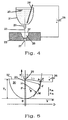
- FIG. 4 illustrates the method according to the invention using an example.
- Liquid metal 20 is located in a crucible 21.
- the molten metal 20 thus forms the negatively charged electrode of the device.
- the crucible 21 is provided on its underside with a calibrated ceramic nozzle 22 from which the molten metal 20 emerges in a jet 23.
- the electrically negatively charged beam 23 flows via the filling opening 37 of the plasma chamber 28 at the oppositely charged electrode 25 over, which is connected to the opposite pole of the voltage source 26.
- the plasma chamber 28 is formed inside the electrode 25.
- other reactants are also introduced, which are within the metal melt 20 of the plasma arc react to the desired powder.
- the procedure is self-evident also for the use of other known devices and methods for plasma generation, such as the use of high frequency current.
- a special feature of the invention is that the plasma is closed in one place the structure of which is firm and stable.
- the starting material whether it is made of a solid body, from granules or consists of powder, distributed within the jet of ionized gas or plasma, which exits the burner at high speed.
- the initiation and dwell time of the The starting material in the plasma is short and random.
- the jet 23 of starting material is directed into a plasma chamber 28 designed in the manner of a paraboloid.
- This chamber 28 has a shape optimized for a given pressure or plasma gas. It goes down into a mixing nozzle 27 which comprises an interior which widens conically outwards. The distance between the jet 23 and the inner wall of the chamber 28 initially varies slowly and decreases faster and faster as the jet 23 moves downward.
- the most favorable shape of the interior of the chamber 28, which is shown in Figure 5 was found by calculations and confirmed by experiments. It is a parabola, which is arranged coaxially to the beam 23 of the starting material.
- FIG. 5 shows the jet 23, which is connected, for example, to the negative pole of the generator 26 and which flows out of a non-conductive ceramic nozzle 29.
- the plasma chamber with its parabolic interior 30 has a filling opening 37 through which the jet 23 flows into the plasma chamber 28 or its interior 30.
- the plasma chamber with a parabolic interior 30 is supplied with the second reaction partner, for example via a further opening (not shown in the figure) in the side wall of the interior 30 or via a nozzle protruding into the filling opening.
- an xy coordinate system is placed over the parabolic interior 30 of a plasma chamber, the beam path within the plasma chamber corresponding to the y axis.
- the parabolic inner wall of the plasma chamber 28 according to the invention is numerical Control (CN) or can be produced with a mold.
- the ionization distance L i corresponds to the length HM of the normal N to the parabola in M minus the radius of the beam, which means, for example, a constant value 1,2,3,4 mm.
- FIG 7 shows that the plasma settles at a point C, which can be conveniently met with the center F (see Figure 5) of the parabola.
- the plasma behaves there in a stable manner and is located at the ionization distance L i from the inner wall of the interior 30. This operating point is particularly stable because the electrode distance decreases slowly at the top and rapidly at the bottom.
- the plasma chamber with the parabolic interior 30 according to FIG. 7 has an upper diameter which corresponds to 2 L i .
- the plasma settles in C at a distance from the inner wall of the interior 30 which is equal to L i .
- the interior 30 of the plasma chamber has in its lower part a passage 31 which has a diameter which is smaller than the length L i .
- the injection of the plasma gas, air being used for this in the exemplary embodiment, is characterized by the directional arrows 32.
- the passage 31 has an outwardly conically widening course.
- an additional gas is fed in by means of an annular nozzle 34 such that a negative pressure is generated in the area of the outlet opening 33.
- the ring nozzle 34 is designed as a supersonic nozzle according to a Venturi nozzle.
- the plasma arc is identified in FIG. 7 by reference number 36.
- this is through a kind of conical mixing tube, whose inner bore is marked with the reference number 35 in FIG. Consequently is the passage 31 with a Venturi nozzle and thus with an area with high flow velocity and low pressure.
- the mixing tube 35 generally has a small taper angle, which can be 7 to 14 °.
- the stoichiometry of the powder to be produced can be changed by changing the amount of gas be determined.
- a mixed crystal powder is made Indium / tin oxide produced in which the indium oxide content 90% by weight and the tin oxide content 10 % By weight.
- a correspondingly low air flow is fed to the plasma, which with the Molten metal in a plasma arc to the desired substoichiometric oxide responds.
- the device according to the invention can also be fed by powder or by granules become.
- the liquid Pb flows out of a crucible, the bottom of which is provided with a ceramic nozzle. It flows with an output of 1000 kg / h through the hole of the nozzle, which has a diameter of 4 mm.
- the O 2 stream necessary for the oxidation is introduced into the parabolic interior of a plasma chamber made of graphite.
- the upper part of the plasma chamber can have a diameter of 60 mm
- the lower part Part have a diameter of 12 mm.
- the voltage between the metal current and the plasma chamber has the consequence that the Plasma settles in a stable axis point.
- the plasma bubble is through the Venturi nozzle sucked in and thereby hurled the oxide powder down.
- the powder thus produced falls finely divided and with a narrow grain size distribution.
Description
Die Erfindung betrifft ein Verfahren für die kontinuierliche Herstellung eines Pulvers durch die Reaktion mindestens zweier Reaktionspartner in einem Plasmalichtbogen, bei dem ein erster und ein zweiter Reaktionspartner dem Plasmalichtbogen zugeführt werden, der mittels einer zwischen einer ersten und einer zweiten Elektrode angelegten Spannung aufrechterhalten wird, wobei mindestens der erste Reaktionspartner elektrisch leitend ist und als erste Elektrode verwendet wird.The invention relates to a method for the continuous production of a powder by the Reaction of at least two reactants in a plasma arc, in which a first and a second reaction partner can be supplied to the plasma arc, which by means of an intermediate a first and a second electrode applied voltage is maintained, wherein at least the first reaction partner is electrically conductive and used as the first electrode becomes.
Weiterhin betrifft die Erfindung eine Vorrichtung für die kontinuierliche Herstellung eines Pulvers durch Reaktion mindestens eines ersten und eines zweiten Reaktionspartners in einem Plasmalichtbogen, mit einer Zuführeinrichtung für die Zufuhr mindestens des ersten Reaktionspartners zu einer Einfüllöffnung einer Plasmakammer, die einen sich in Richtung auf einen der Einfüllöffnung gegenüberliegenden Durchlaß verjüngenden Innenraum aufweist, und mit mindestens zwei mit einem Generator verbundenen Elektroden zur Aufrechterhaltung eines Plasmalichtbogens in der Plasmakammer, wobei die erste Elektrode durch den ersten Reaktionspartner gebildet wird.The invention further relates to a device for the continuous production of a powder by reaction of at least a first and a second reaction partner in a plasma arc, with a feed device for the feed of at least the first reactant to a filling opening of a plasma chamber, which is directed towards one of the filling opening has opposite passage tapered interior, and with at least two electrodes connected to a generator to maintain a plasma arc in the plasma chamber, the first electrode being formed by the first reaction partner.
Das Plasma ist ein komplexes Medium, das man bei sehr hohen Temperaturen von beispielsweise 3000 °C erhält. Es ist sehr reaktiv, so daß die chemischen Reaktionen mit hoher Geschwindigkeit ablaufen. Plasma wird durch die Ionisation eines Gases durch elektrische Entladung von Gleichstrom, bei Hochfrequenzentladung und bei Mikrowellenentladung gebildet. Beispiele für die derzeitige Nutzung sind: Reduktion von Eisenerz durch Einspritzen von Eisenerz (Oxid) und Kohle in einen Plasmabrenner; durch Einspritzen zahlreicher Metalloxide Cr2O3, SiO2, CaO, MgO ...The plasma is a complex medium that can be obtained at very high temperatures of, for example, 3000 ° C. It is very reactive, so the chemical reactions take place at high speed. Plasma is formed by the ionization of a gas through electrical discharge of direct current, with high-frequency discharge and with microwave discharge. Examples of current use are: reduction of iron ore by injecting iron ore (oxide) and coal into a plasma torch; by injecting numerous metal oxides Cr 2 O 3 , SiO 2 , CaO, MgO ...
Plasmalichtbogen werden vor allem in der Metallurgie bei hohen Temperaturen über 1500 °C verwendet. Sie verbrauchen große Mengen an elektrischer Energie. Sie benötigen Elektroden, die nach Gebrauch als Abfall anfallen und sind insoweit umweltverschmutzend.Plasma arcs are used primarily in metallurgy at high temperatures above 1500 ° C used. They consume large amounts of electrical energy. You need electrodes that accumulate as waste after use and are therefore polluting to the environment.
Zwar kann auch ein Induktionsplasma ohne Elektroden erzeugt werden, seine Leistung ist jedoch schwächer, wie dies in der Dokumentation "Les Plasmas Industriels" des französischen Ministeriums für Unterricht, Forschung und Hochschulwesen - La Documentation Française, Nr. 10, 1986 - ) beschrieben ist.An induction plasma can also be generated without electrodes, but its performance is weaker, as in the document "Les Plasmas Industriels" of the French ministry for teaching, research and higher education - La Documentation Française, no. 10, 1986 -).
Ein Verfahren und eine Vorrichtung gemäß der angegebenen Gattung sind aus der schweizerischen Patentschrift CH 281 749 bekannt. Darin wird ein Verfahren zur Herstellung von Metall-Halogeniden beschrieben, wobei eine aus einem Gemisch von Mineralien der entsprechenden Metalle und aus Kohlenstoff bestehende Anode hergestellt wird, zwischen dieser Anode und einer Kathode aus Kohlenstoff ein Lichtbogen in einer halogenhaltigen Atmosphäre erzeugt und so das Metall-Halogenid gebildet wird.A method and a device according to the type specified are from the Swiss Patent CH 281 749 known. It describes a process for the production of metal halides described, one of a mixture of minerals of the corresponding Metals and carbon anode is made between this anode and one Carbon cathode creates an arc in a halogen-containing atmosphere and so the metal halide is formed.
Dabei wird die Anode verbraucht. Wegen der Inhomogenität des Anodenmaterials brennt das Plasma ungleichmäßig. Zudem ist die Herstellung der Elektrode aufwendig und teuer.This consumes the anode. This burns due to the inhomogeneity of the anode material Plasma uneven. In addition, the manufacture of the electrode is complex and expensive.
Eine Vorrichtung gemäß der angegebenen Gattung ist aus der britischen Patentschrift GB 959,027 bekannt. Die dort beschriebene Plasmaspritz-Vorrichtung weist eine Plasmakammer und eine Zuführeinrichtung für die Zuführung eines metallischen als Elektrode geschalteten Drahtes in die Plasmakammer auf. Die Zuführeinrichtung ist an ihrer Unterseite mit einem Auslaß für den Draht versehen, der koaxial zu dem nach oben, in Richtung der Zuführeinrichtung, offenen Innenraum der Plasmakammer verläuft. Der Innenraum der Plasmakammer verengt sich nach unten konisch in Richtung einer Auslaßdüse.A device according to the type specified is from the British patent GB 959,027 known. The plasma spray device described there has a plasma chamber and a feed device for feeding a metallic as an electrode Wire into the plasma chamber. The feed device has an outlet on its underside for the wire, which is coaxial to the upward, towards the feeder, open interior of the plasma chamber runs. The interior of the plasma chamber narrows downwards tapered towards an outlet nozzle.
Weiterhin ist aus US 2,157,498 ein Verfahren und eine Vorrichtung zur Herstellung von metallischen Überzügen aus mittels eines Lichtbogens in einer Kammer verdampften Metallen bekannt. Das zu verdampfende Metall wird bevorzugt in fester Form als Draht oder als Metallseele einer zunächst durchbohrten Elektrode (beispielsweise mit einem Kohlenstoffmantel) zugeführt, die Zugabe als Metallpulver wird ebenfalls offenbart. Zur Erhöhung des Drucks in der Druckkammer wird ein Hilfsdruckmittel (Gas) eingeleitet, das auch die Abführung des erzeugten Metalldampfes über eine einen Auslaßkanal aufweisende Elektrode unterstützt.Furthermore, from US 2,157,498 is a method and an apparatus for the production of metallic Coatings made of metals vaporized by means of an arc in a chamber are known. The metal to be evaporated is preferably in solid form as a wire or as a metal core first fed pierced electrode (for example with a carbon jacket), the Addition as metal powder is also disclosed. To increase the pressure in the pressure chamber an auxiliary pressure medium (gas) is introduced, which also removes the metal vapor generated supported by an electrode having an outlet channel.
Es hat sich gezeigt, daß bei den bekannten Vorrichtungen das in der Plasmakammer erzeugte Plasma nicht ausreichend stabilisiert werden kann.It has been shown that in the known devices that generated in the plasma chamber Plasma cannot be stabilized sufficiently.
Der vorliegenden Erfindung liegt daher einerseits die Aufgabe zugrunde, ein einfaches und preisgünstiges Verfahren für die kontinuierliche und reproduzierbare Herstellung eines Pulvers durch die Reaktion mindestens zweier Reaktionspartner in einem Plasmalichtbogen anzugeben und eine Vorrichtung hierfür bereitzustellen, die ein homogenes und gleichmäßiges Plasma und somit reproduzierbare Ergebnisse gewährleistet.The present invention is therefore based on the one hand the task of a simple and inexpensive Process for the continuous and reproducible production of a powder by specify the reaction of at least two reactants in a plasma arc and one To provide device for this, which is a homogeneous and uniform plasma and thus reproducible results guaranteed.
Hinsichtlich des Verfahrens wird diese Aufgabe erfindungsgemäß dadurch gelöst, daß der erste Reaktionspartner dem Plasmalichtbogen in schmelzflüssiger Form zugeführt wird, wobei der Plasmalichtbogen in einem im wesentlichen parabelförmigen Innenraum einer Plasmakammer aufrechterhalten wird.With regard to the method, this object is achieved in that the first Reactant is supplied to the plasma arc in molten form, the Plasma arc in a substantially parabolic interior of a plasma chamber is maintained.
Der erste Reaktionspartner liegt in Form einer Schmelze vor. Es ist nicht erforderlich, eine den ersten Reaktionspartner enthaltende, feste Elektrode herzustellen. Abnutzungserscheinungen oder Verschmutzungen durch Abrieb, wie sie beispielsweise bei einem Induktionsplasma zu beobachten sind, sind daher nicht zu befürchten. Die Zufuhr des ersten Reaktionpartners zu dem Plasmalichtbogen kann beispielsweise unter Ausnutzung der Schwerkraft aufgrund seines eigenen Gewichtes beruhen, indem ein Strom eines den ersten Reaktionspartner enthaltenden Materials dem Plasmalichtbogen von oben zugeführt wird. Dadurch, daß der erste Reaktionspartner in fluider Form dem Plasmalichtbogen zugeführt wird, läßt sich auch eine homogene Verteilung des Reaktionspartners innerhalb eines derartigen Stromes leicht erreichen.The first reactant is in the form of a melt. It is not necessary to have one to produce the first reactant-containing solid electrode. Signs of wear or soiling due to abrasion, as observed, for example, with an induction plasma are therefore not to be feared. The supply of the first reaction partner to the For example, plasma arcing can take advantage of gravity due to its own Weight based by a stream of a material containing the first reactant the plasma arc is fed from above. Because the first reactant A homogeneous distribution can also be supplied to the plasma arc in fluid form easily reach the reactant within such a stream.
Der zweite Reaktionspartner kann ebenfalls in fluider Form, beispielsweise als Gas, dem Plasmalichtbogen zugeführt werden. Dadurch wird ein besonders stabiles und homogenes Plasma erhalten.The second reaction partner can also in fluid form, for example as a gas, the plasma arc be fed. This creates a particularly stable and homogeneous plasma receive.
Vorteilhafterweise wird der erste Reaktionspartner als Elektrode mit negativem Potential geschaltet.The first reaction partner is advantageously an electrode with a negative potential switched.
Aus Gründen der Energieeinsparung und der Stabilisierung des Plasmalichtbogens wird dieser vorteilhafterweise mit einer Energie versehen, die der freien Bildungsenthalpie der aus den Reaktionspartners herzustellenden chemischen Verbindung zuzüglich des Wärmeverlustes im Plasmalichtbogen entspricht.For reasons of energy saving and the stabilization of the plasma arc, this is advantageously provided with an energy that the free enthalpy of education from the Reactive partner to produce chemical compound plus the heat loss in the Plasma arc corresponds.
Ein besonders stabiles Plasma wird erhalten, wenn der Plasmalichtbogen in einer Plasmakammer mit einem im Querschnitt gesehen im wesentlichen parabelförmigen Innenraum, der mit einer Einfüllöffnung für den ersten Reaktionspartner und mit einem der Einfüllöffnung gegenüberliegenden Durchlaß versehenen ist, aufrechterhalten wird. Über den Durchlaß wird das im Plasmalichtbogen gebildete Reaktionsprodukt aus der Plasmakammer abgegeben. Der Innenraum hat im wesentlichen die Form eines Paraboloids.A particularly stable plasma is obtained when the plasma arc is in a plasma chamber with a parabolic interior seen in cross section, which with a Filling opening for the first reactant and with one opposite the filling opening Passage is maintained. About the passage that is in the plasma arc formed reaction product released from the plasma chamber. The interior has essentially the shape of a paraboloid.
Dabei hat es sich besonders bewährt, daß der Plasmakammer mindestens der erste Reaktionspartner in einem Strahl zugefürht wird, wobei die lange Achse des parabelförmigen Innenraums der Plasmakammer koaxial zum dem Strahl verläuft.It has proven particularly useful that the plasma chamber has at least the first reaction partner is fed in a beam, the long axis of the parabolic interior the plasma chamber is coaxial with the beam.
Der Plasmalichtbogen wird vorteilhafterweise in einem der Zentren der Parabel gezündet. Das Zentrum der Parabel sollte dasjenige sein, das dem Durchlaß der Plasmakammer am nächsten liegt. Dadurch wird ein besonders stabiles Plasma erreicht.The plasma arc is advantageously ignited in one of the centers of the parabola. The The center of the parabola should be the one closest to the passage of the plasma chamber lies. This results in a particularly stable plasma.
Ein besonders stabiles Plasma wird dann erhalten, wenn der Durchlaß der Plasmakammer nach außen hin mit einem Mischrohr verlängert wird, an dessen Auslaßöffnung ein Unterdruck aufrechterhalten wird. Dabei kann das Mischrohr als sogenannte "Venturidüse" wirken.A particularly stable plasma is obtained when the passage through the plasma chamber is extended on the outside with a mixing tube, a negative pressure is maintained at the outlet opening becomes. The mixing tube can act as a so-called "Venturi nozzle".
Vorteilhafterweise wird der Unterdruck mittels einer sich an das Mischrohr anschließenden Überschalldüse aufrechterhalten.The negative pressure is advantageously generated by means of a supersonic nozzle adjoining the mixing tube maintain.
Als erste Reaktionspartner kommen für das erfindungsgemäße Verfahren beispielsweise folgende
Metalle in Frage:
Als zweite Reaktionspartner kommen beispielsweise folgende Gase in Frage:
Besonders bewährt hat sich ein Verfahren, bei dem als erster Reaktionspartner eine Schmelze von Indium und Zinn, und als zweiter Reaktionspartner ein oxidierendes Gas eingesetzt wird.A process in which a melt is the first reaction partner has proven particularly useful of indium and tin, and an oxidizing gas is used as the second reaction partner.
Hinsichtlich der Vorrichtung wird die oben genannte Aufgabe ausgehend von der eingangs genannten Vorrichtung erfindungsgemäß dadurch gelöst, daß die Zuführeinrichtung ein Gefäß für die Aufnahme des ersten Reaktionspartners umfaßt, das an seiner der Einfüllöffnung der Plasmakammer zugewandten Unterseite mit einem Auslaß versehen ist, der in Richtung des im wesentlichen parabelförmigen Innenraums der Plasmakammer gerichtet ist.With regard to the device, the above-mentioned task is based on the above-mentioned Device according to the invention solved in that the feed device a vessel for includes the reception of the first reactant, which at its the filling opening of the plasma chamber facing bottom is provided with an outlet in the direction of the substantially parabolic interior of the plasma chamber is directed.
Der erste Reaktionspartner wird aus dem Gefäß dem Plasmalichtbogen in schmelzflüssiger Form zugeführt. Dies ermöglicht die Durchführung des erfindungsgemäßen Verfahrens, dessen Vorteile oben erläutert sind.The first reaction partner becomes the plasma arc in the molten liquid Form fed. This enables the method according to the invention to be carried out Advantages are explained above.
Durch die bevorzugte Ausführungsform mit einem im Querschnitt im wesentlichen parabelförmigen Innenraum der Plasmakammer wird ein sowohl hinsichtlich der örtlichen Fixierung, seiner geometrischen Ausbildung als auch ein hinsichtlich seiner Energie besonders stabiler Plasmalichtbogen ermöglicht. Abgesehen von Unstetigkeiten beispielsweise im oberen oder unteren Bereich bildet der Innenraum ein Paraboloid.Due to the preferred embodiment with a parabolic cross section Interior of the plasma chamber is a both in terms of local fixation, its geometric training as well as a particularly stable plasma arc in terms of its energy enables. Apart from discontinuities, for example in the upper or lower area the interior forms a paraboloid.
Vorteilhafte Ausführungsformen der Vorrichtung ergeben sich aus den übrigen Unteransprüchen. Nachfolgend wird ein Ausführungsbeispiel der Erfindung anhand der Patentzeichnung näher erläutert. In der Zeichnung zeigen im einzelnen in schematischer Darstellung
- Fig. 1
- das Prinzip der Reduktion eines Erzes durch einen Plasmalichtbogen,
- Fig. 2
- das Prinzip des Einspritzens von Pulver in eine Plasmaflamme,
- Fig. 3
- das Prinzip des Induktionsplasmas,
- Fig. 4
- ein Ausführungsbeispiel der erfindungsgemäßen Vorrichtung in einem Gesamtüberblick,
- Fig. 5
- eine vergrößerte Darstellung der in Fig. 4 dargestellten Plasmakammer,
- Fig. 6
- einen Ausschnitt der in Figur 5 gezeigten Plasmakammer zum Zwecke der Erläuterung des Ionisationsabstandes und
- Fig. 7
- ein weiteres Beispiel einer Plasmakammer bei einer erfindungsgemäßen Vorrichtung.
- Fig. 1
- the principle of reducing an ore through a plasma arc,
- Fig. 2
- the principle of injecting powder into a plasma flame,
- Fig. 3
- the principle of induction plasma,
- Fig. 4
- an embodiment of the device according to the invention in a general overview,
- Fig. 5
- 3 shows an enlarged illustration of the plasma chamber shown in FIG. 4,
- Fig. 6
- a section of the plasma chamber shown in Figure 5 for the purpose of explaining the ionization distance and
- Fig. 7
- another example of a plasma chamber in a device according to the invention.
Figur 1 veranschaulicht das Prinzip der Reduktion eines Erzes durch einen Plasmalichtbogen. Der Brenner 1 und die Elektrode 2 werden durch den von einem Generator 3 erzeugten Gleichstrom gespeist. Das Plasmagas 4 wird dem Brenner zugeführt, während ein externes Gas 7 eingeführt oder abgesaugt wird. Figure 1 illustrates the principle of the reduction of an ore by a plasma arc. The burner 1 and the electrode 2 are fed by the direct current generated by a generator 3. The plasma gas 4 is supplied to the burner while an external gas 7 is introduced or extracted.
Das Oxid 5 oder die Bestandteile werden dem Plasmalichtbogen 9 durch einen Trichter 8 zugeführt. Die im Plasmalichtbogen 9 entstehende pulverförmige Verbindung wird in einem Behälter 6 aufgefangen.The oxide 5 or the components are fed to the plasma arc 9 through a funnel 8. The powdery compound formed in the plasma arc 9 is in a container 6 caught.
Figur 2 veranschaulicht ein weiteres gebräuchliches Verfahren zur Herstellung eines Pulvers in einem Plasmalichtbogen, wobei ein Ausgangspulver 10 mittels eines Zerstäubers 11 in die Flamme 11 eines Brenners 13 eingespritzt wird. Anhand der Darstellung ist ersichtlich, daß das so hergestellte Pulver nicht sehr homogen sein kann. FIG. 2 illustrates a further customary method for producing a powder in a plasma arc, in which case a starting powder 10 is injected into the flame 11 of a burner 13 by means of an atomizer 11. It can be seen from the illustration that the powder produced in this way cannot be very homogeneous.
Figur 3 veranschaulicht das Prinzip des Induktionsplasmas. In ein Quarzrohr 14 wird ein Gas 15 eingeleitet, das innerhalb einer Hochfrequenzspule 19 durch einen energiereichen Strahl 16 mit hoher Geschwindigkeit ionisiert wird und erzeugt auf diese Weise das Plasma 17, in dem das gewünschte Reaktionsprodukt 18 erzeugt wird. Figure 3 illustrates the principle of the induction plasma. A gas 15 is introduced into a quartz tube 14, which is ionized within a high-frequency coil 19 by a high-energy beam 16 at high speed and in this way generates the plasma 17 in which the desired reaction product 18 is generated.
Figur 4 veranschaulicht das erfindungsgemäße Verfahren anhand eines Beispiels. Flüssiges Metall 20 befindet sich in einem Tiegel 21. Innerhalb der Metallschmelze 20 ist ein Stab 24 aus einem hochtemperaturstabilen, elektrisch leitenden Cermet angeordnet, der mit einer Spannungsquelle 26 verbunden ist. Die Metallschmelze 20 bildet so die negativ geladene Elektrode der Vorrichtung. FIG. 4 illustrates the method according to the invention using an example. Liquid metal 20 is located in a crucible 21. A rod 24 made of a high-temperature stable, electrically conductive cermet, which is connected to a voltage source 26, is arranged within the metal melt 20. The molten metal 20 thus forms the negatively charged electrode of the device.
Der Tiegel 21 ist an seiner Unterseite mit einer kalibrierten Keramikdüse 22 versehen, aus der die Metallschmelze 20 in einem Strahl 23 austritt. Der elektrisch negativ geladene Strahl 23 fließt über die Einfüllöffnung 37 der Plasmakammer 28 an der entgegengesetzt geladenen Elektrode 25 vorbei, die mit dem Gegenpol der Spannungsquelle 26 verbunden ist. Die Plasmakammer 28 ist innerhalb der Elektrode 25 ausgebildet. In die Plasmakammer 28 wird auch der weitere oder werden auch noch weitere Reaktionspartner eingeleitet, die mit der Metallschmelze 20 innerhalb des Plasmalichtbogens zu dem gewünschten Pulver reagieren. Selbstverständlich ist das Verfahren auch für die Verwendung anderer bekannter Vorrichtungen und Verfahren zur Plasmagenerierung, wie zum Beispiel die Verwendung von Hochfrequenzstrom, geeignet.The crucible 21 is provided on its underside with a calibrated ceramic nozzle 22 from which the molten metal 20 emerges in a jet 23. The electrically negatively charged beam 23 flows via the filling opening 37 of the plasma chamber 28 at the oppositely charged electrode 25 over, which is connected to the opposite pole of the voltage source 26. The plasma chamber 28 is formed inside the electrode 25. The further or is also in the plasma chamber 28 other reactants are also introduced, which are within the metal melt 20 of the plasma arc react to the desired powder. The procedure is self-evident also for the use of other known devices and methods for plasma generation, such as the use of high frequency current.
Eine Besonderheit der Erfindung besteht darin, daß das Plasma an einem Ort verschlossen wird, der von seinem Aufbau her fest und stabil ist. Bei den bekannten Verfahren, wie beispielsweise in Figur 2 dargestellt, wird das Ausgangsmaterial, ob es nun aus einem festen Körper, aus Granulaten oder aus Pulver besteht, innerhalb des Strahles aus ionisiertem Gas oder Plasma verteilt, der mit hoher Geschwindigkeit aus dem Brenner austritt. Die Einleitung und Verweilzeit des Ausgangsmaterials in das Plasma sind kurz und zufallsbedingt.A special feature of the invention is that the plasma is closed in one place the structure of which is firm and stable. In the known methods, such as shown in Figure 2, the starting material, whether it is made of a solid body, from granules or consists of powder, distributed within the jet of ionized gas or plasma, which exits the burner at high speed. The initiation and dwell time of the The starting material in the plasma is short and random.
Demgegenüber wird bei dem erfindungsgemäßen Verfahren der Strahl 23 aus Ausgangsmaterial, wie beispielsweise in der Vorrichtung gemäß Figur 4 dargestellt, in eine nach Art eines Paraboloids ausgebildete Plasmakammer 28 geleitet. Diese Kammer 28 besitzt eine für einen gegebenen Druck oder ein gegebenes Plasmagas optimierte Form. Sie geht nach unten in eine Mischdüse 27 über, die einen nach außen sich konisch erweiternden Innenraum umfaßt. Der Abstand zwischen dem Strahl 23 und der Innenwandung der Kammer 28 variiert zunächst langsam und nimmt auf dem Weg des Strahles 23 nach unten immer schneller ab. Die günstigste Form des Innenraumes der Kammer 28, die in Figur 5 dargestellt wird, wurde durch Berechnungen herausgefunden und durch Experimente bestätigt. Es handelt sich um eine Parabel, die koaxial zum Strahl 23 des Ausgangsmaterials angeordnet ist.In contrast, in the method according to the invention, the jet 23 of starting material, as shown for example in the device according to FIG. 4, is directed into a plasma chamber 28 designed in the manner of a paraboloid. This chamber 28 has a shape optimized for a given pressure or plasma gas. It goes down into a mixing nozzle 27 which comprises an interior which widens conically outwards. The distance between the jet 23 and the inner wall of the chamber 28 initially varies slowly and decreases faster and faster as the jet 23 moves downward. The most favorable shape of the interior of the chamber 28, which is shown in Figure 5 , was found by calculations and confirmed by experiments. It is a parabola, which is arranged coaxially to the beam 23 of the starting material.
In Figur 5 ist der Strahl 23 zu erkennen, der zum Beispiel mit dem Minuspol des Generators 26
verbunden ist und der aus einer nichtleitenden Keramikdüse 29 herausfließt. Die Plasmakammer
mit ihrem parabelförmigen Innenraum 30 weist eine Einfüllöffnung 37 auf, durch die der Strahl 23
in die Plasmakammer 28 bzw. deren Innenraum 30 einfließt. Außerdem wird der Plasmakammer
mit parabelförmigen Innenraum 30 der zweite Reaktionspartner, beispielsweise über eine weitere
(in der Figur nicht dargestellte) Öffnung in der Seitenwand des Innenraumes 30 oder über eine
in die Einfüllöffnung hineinragende Düse, zugeführt. In der Figur 5 ist über dem parabelförmigen
Innenraum 30 einer Plasmakammer ein xy-Koordinatensytem gelegt, wobei der Strahlverlauf
innerhalb der Plasmakammer der y-Achse entspricht. Die Parabel, die durch ihr Zentrum F
und ihre Leitgerade D gekennzeichnet ist, hat auf die x- und y- Achse bezogen, folgende
Gleichung:
Die parabelförmige Innenwandung der Plasmakammer 28 gemäß der Erfindung ist durch numerische Steuerung (CN) oder mit einem Formwerkzeug herstellbar.The parabolic inner wall of the plasma chamber 28 according to the invention is numerical Control (CN) or can be produced with a mold.
Für den Fall eines kontinuierlichen Strahles, der nach dem Newtonschen Gesetz aufgrund seiner
Geschwindigkeit und Viskosität auf einer Länge Y1 erhalten bleibt, und unter der Annahme der
Ionisationsabstand in Abhängigkeit vom Gas und vom Druck innerhalb des parabelförmigen Innenraumes
30 der Plasmakammer betrage Li, hat sich ein Abstand L von mindestens 2 Li zwischen
dem Strahl 23 im Bereich der Keramikdüse 29 und der Innenwandung des Innenraumes
30 in diesem Bereich als ausreichend erwiesen.
Dies genügt, um die Parabel zu kennzeichnen, die eine Kurve 2. Grades ist und durch den Punkt
"A" und den Eigenschnittpunkt "B" in der folgenden Formel definiert wird:
Es wird also davon ausgegangen, daß "a" eine bekannte Konstante ist, deren Ermittlung für den Fachmann auf diesem Gebiet aus den oben gemachten Angaben selbstverständlich ist.It is therefore assumed that "a" is a known constant, the determination of which for the Specialist in this field is self-evident from the information given above.
Figur 6 veranschaulicht, daß dieser parabelförmige Innenraum 30 der Plasmakammer einen
möglichst stabilen Plasmalichtbogen ergibt. In der Tat ergibt ein Punkt M (x,y) von P und seiner
Tangente die Gleichung der Ableitung von P.
Der Ionisationsabstand Li entspricht der Länge HM der Normalen N zur Parabel in M minus dem
Radius des Strahls, das bedeutet zum Beispiel einen konstanten Wert 1,2,3,4 mm. Die Gleichung
der Normalen N wird von der Gleichung von T abgeleitet.
Berechnet werden soll der Ionisationsabstand in der Plasmakammer in bezug auf den der Plasmakammer
zugeführten Strahl nach HM.
Diese Berechnung ist eine Bestätigung dessen, was Figur 5 und Figur 6 veranschaulichen. Dies bedeutet, daß die Innenwandung des Innenraumes 30 nahe dem Austritt des Strahles 23 aus der Keramikdüse 29 (benachbart zum Punkt A) praktisch parallel zum Strahl 23 verläuft, sich danach sehr schnell an den Strahl 23 annähert und schließlich, wie in Punkt B dargestellt, in Kontakt mit dem Strahl 23 tritt.This calculation is a confirmation of what Figure 5 and Figure 6 illustrate. This means that the inner wall of the interior 30 near the exit of the jet 23 the ceramic nozzle 29 (adjacent to the point A) runs practically parallel to the jet 23, thereafter very quickly approaches the beam 23 and finally, as shown in point B, in contact with the beam 23 occurs.
Figur 7 zeigt, daß sich das Plasma an einem Punkt C niederläßt, den man günstigerweise mit dem Zentrum F (siehe Figur 5) der Parabel zusammentreffen läßt. Das Plasma verhält sich dort stabil und befindet sich im Ionisationsabstand Li von der Innenwandung des Innenraumes 30. Dieser Betriebspunkt ist besonders stabil, da sich der Elektrodenabstand oben langsam und unten schnell verkleinert. Figure 7 shows that the plasma settles at a point C, which can be conveniently met with the center F (see Figure 5) of the parabola. The plasma behaves there in a stable manner and is located at the ionization distance L i from the inner wall of the interior 30. This operating point is particularly stable because the electrode distance decreases slowly at the top and rapidly at the bottom.
Die Plasmakammer mit dem parabelförmigen Innenraum 30 gemäß Figur 7 hat einen oberen Durchmesser, der 2 Li entspricht. Das Plasma läßt sich mit einem Abstand zur Innenwandung des Innenraumes 30, der gleich Li ist, in C nieder. Der Innenraum 30 der Plasmakammer weist in seinem unteren Teil einen Durchlaß 31 auf, der einen Durchmesser besitzt, der kleiner ist als die Länge Li. Das Einspritzen des Plasmagases, im Ausführungsbeispiel wird hierfür Luft verwendet, wird durch die Richtungspfeile 32 charakterisiert. Der Durchlaß 31 weist einen sich nach außen konisch erweiternden Verlauf auf. Im Bereich seiner Auslaßöffnung 33 wird mittels einer Ringdüse 34 ein zusätzliches Gas eingespeist, derart, daß im Bereich der Auslaßöffnung 33 ein Unterdruck erzeugt wird. Die Ringdüse 34 ist dabei als Überschalldüse gemäß einer Venturidüse ausgebildet. Der Plasmalichtbogen ist in der Figur 7 mit der Bezugsziffer 36 gekennzeichnet.The plasma chamber with the parabolic interior 30 according to FIG. 7 has an upper diameter which corresponds to 2 L i . The plasma settles in C at a distance from the inner wall of the interior 30 which is equal to L i . The interior 30 of the plasma chamber has in its lower part a passage 31 which has a diameter which is smaller than the length L i . The injection of the plasma gas, air being used for this in the exemplary embodiment, is characterized by the directional arrows 32. The passage 31 has an outwardly conically widening course. In the area of its outlet opening 33, an additional gas is fed in by means of an annular nozzle 34 such that a negative pressure is generated in the area of the outlet opening 33. The ring nozzle 34 is designed as a supersonic nozzle according to a Venturi nozzle. The plasma arc is identified in FIG. 7 by reference number 36.
Durch diese Ausführung des Durchlasses 31 wird dieser durch eine Art konisches Mischrohr, dessen Innenbohrung in Figur 7 mit der Bezugsziffer 35 gekennzeichnet ist, verlängert. Somit steht der Durchlaß 31 mit einer Venturi-Düse und damit mit einem Bereich mit hoher Strömungsgeschwindigkeit und niedrigem Druck in Verbindung. Das Mischrohr 35 besitzt im allgemeinen einen kleinen Konizitäts-Winkel, der 7 bis 14° betragen kann.Through this design of the passage 31, this is through a kind of conical mixing tube, whose inner bore is marked with the reference number 35 in FIG. Consequently is the passage 31 with a Venturi nozzle and thus with an area with high flow velocity and low pressure. The mixing tube 35 generally has a small taper angle, which can be 7 to 14 °.
Die Stöchiometrie des herzustellenden Pulvers kann durch eine Veränderung der Gasmenge beliebig bestimmt werden. In einer bevorzugten Verfahrensweise wird ein Mischkristallpulver aus Indium-/Zinnoxid hergestellt, bei dem der Indiumoxidanteil 90 Gew.-% und der Zinnoxidanteil 10 Gew.-% beträgt. Um ein Mischkristallpulver mit unterstöchiometrischem Sauerstoffgehalt herzustellen, wird dem Plasma ein entsprechend niedrig gehaltener Luftstrom zugeführt, der mit der Metallschmelze im Plasmalichtbogen zu dem gewünschten unterstöchiometrischen Oxid reagiert.The stoichiometry of the powder to be produced can be changed by changing the amount of gas be determined. In a preferred procedure, a mixed crystal powder is made Indium / tin oxide produced in which the indium oxide content 90% by weight and the tin oxide content 10 % By weight. In order to produce a mixed crystal powder with substoichiometric oxygen content, a correspondingly low air flow is fed to the plasma, which with the Molten metal in a plasma arc to the desired substoichiometric oxide responds.
Die Vorrichtung gemäß der Erfindung kann auch durch Pulver oder durch Granulate gespeist werden.The device according to the invention can also be fed by powder or by granules become.
Ein Beispiel für die industrielle Anwendung der Erfindung ist die ununterbrochene Herstellung von Bleioxid PbO. Zur Herstellung von 1000 kg Oxid müssen 928 kg Blei und 72 kg Sauerstoff, d.h. 101 m3, verwendet werden. Des weiteren müssen 96 kcal/mol (Molgewicht von PbO = 224 g), d.h. ca. 430 000 kcal, zugeführt werden. Das flüssige Pb fließt aus einem Tiegel, dessen Boden mit einer Keramikdüse versehen ist. Es fließt mit einem Ausstoß von 1000 kg/h durch das Loch der Düse, die einen Durchmesser von 4 mm hat. Der für die Oxidation notwendige O2-Strom wird in den parabelförmigen Innenraum einer Plasmakammer aus Graphit eingeleitet. An example of the industrial application of the invention is the continuous production of lead oxide PbO. 928 kg of lead and 72 kg of oxygen, ie 101 m 3 , must be used to produce 1000 kg of oxide. Furthermore, 96 kcal / mol (molecular weight of PbO = 224 g), ie approx. 430,000 kcal, must be added. The liquid Pb flows out of a crucible, the bottom of which is provided with a ceramic nozzle. It flows with an output of 1000 kg / h through the hole of the nozzle, which has a diameter of 4 mm. The O 2 stream necessary for the oxidation is introduced into the parabolic interior of a plasma chamber made of graphite.
Der obere Teil der Plasmakammer kann zum Beispiel einen Durchmesser von 60 mm, der untere Teil einen Durchmesser von 12 mm haben.For example, the upper part of the plasma chamber can have a diameter of 60 mm, the lower part Part have a diameter of 12 mm.
Die Spannung zwischen dem Metallstrom und der Plasmakammer hat zur Folge, daß sich das Plasma in einem stabilen Achsenpunkt niederläßt. Die Plasmablase wird durch die Venturidüse angesaugt und dadurch das Oxidpulver nach unten geschleudert. Das so hergestellte Pulver fällt feinteilig und mit enger Korngrößenverteilung an.The voltage between the metal current and the plasma chamber has the consequence that the Plasma settles in a stable axis point. The plasma bubble is through the Venturi nozzle sucked in and thereby hurled the oxide powder down. The powder thus produced falls finely divided and with a narrow grain size distribution.
Claims (9)
- A method for the continuous production of a powder through the reaction of at least two reaction partners in a plasma arc, in which a first and a second reaction partner are supplied to the plasma arc, which is maintained by means of a voltage applied between a first and a second electrode, at least the first reaction partner being electrically conductive and being used as electrode, characterised in that the first reaction partner (20) is supplied to the plasma arc (36) in a molten form, the plasma arc (36) being maintained in a substantially parabolic interior (30) of a plasma chamber (28).
- The method according to Claim 1, characterised in that the first reaction partner (20) is connected as electrode with negative potential.
- The method according to Claim 1 or 2, characterised in that the plasma arc (36) is provided with an energy which corresponds to the free formation enthalpy of the powder which is to be produced including the heat loss in the plasma arc (36).
- The method according to any of the preceding claims, characterised in that the plasma arc (36) is ignited in one of the centres (F) of the parabola.
- The method according to any of the preceding claims, characterised in that at least the first reaction partner (20) is supplied to the plasma chamber (28) in a jet (23), the long axis of the parabolic interior (30) of the plasma chamber (28) running coaxially to the jet (23).
- The method according to any of the preceding claims, characterised in that as first reaction partner (20) a melt of tin and indium is used and as second reaction partner a gas containing oxygen is used.
- A device for the continuous production of a powder through reaction at least of a first and of a second reaction partner in a plasma arc, with a supply arrangement for the supply at least of the first reaction partner to a filling opening of the plasma chamber, which has a parabolic interior narrowing in the direction of a passage lying opposite the filling opening, and at least two electrodes connected with a generator to maintain a plasma arc in the plasma chamber, the first electrode being formed by the first reaction partner, the supply arrangement comprising a vessel (21) to receive the first recation partner (20), which on its underside facing the filling opening (37) of the plasma chamber (28) is provided with an outlet (22) which is directed in the direction of the substantially parabolic interior (30) of the plasma chamber (28).
- The device according to Claim 7, characterised in that the passage (31) of the plasma chamber (28) is extended towards the exterior with a mixing tube (27; 35), the internal cross-section of which widens conically from the plasma chamber (28) viewed in the direction of its outlet opening (33), whereby a vacuum is built up at the outlet opening (33).
- The device according to Claim 8, characterised in that adjoining the mixing tube (27; 35) is an ultrasonic nozzle (34), which serves to maintain the vacuum.
Applications Claiming Priority (3)
| Application Number | Priority Date | Filing Date | Title |
|---|---|---|---|
| FR9410874A FR2724123A1 (en) | 1994-09-07 | 1994-09-07 | DEVICE FOR STABILIZING A CONTINUOUS CHEMICAL REACTION BETWEEN SEVERAL BODIES IN A PLASMA |
| FR9410874 | 1994-09-07 | ||
| PCT/EP1995/003513 WO1996007475A1 (en) | 1994-09-07 | 1995-09-07 | Method of preparing a powder in a plasma arc and device for carrying out said method |
Publications (2)
| Publication Number | Publication Date |
|---|---|
| EP0726806A1 EP0726806A1 (en) | 1996-08-21 |
| EP0726806B1 true EP0726806B1 (en) | 1999-06-23 |
Family
ID=9466868
Family Applications (1)
| Application Number | Title | Priority Date | Filing Date |
|---|---|---|---|
| EP95932003A Expired - Lifetime EP0726806B1 (en) | 1994-09-07 | 1995-09-07 | Method of preparing a powder in a plasma arc and device for carrying out said method |
Country Status (8)
| Country | Link |
|---|---|
| US (1) | US5723027A (en) |
| EP (1) | EP0726806B1 (en) |
| JP (1) | JP3462215B2 (en) |
| KR (1) | KR100300885B1 (en) |
| CN (1) | CN1135190A (en) |
| DE (1) | DE59506276D1 (en) |
| FR (1) | FR2724123A1 (en) |
| WO (1) | WO1996007475A1 (en) |
Cited By (1)
| Publication number | Priority date | Publication date | Assignee | Title |
|---|---|---|---|---|
| WO2010108591A1 (en) | 2009-03-27 | 2010-09-30 | W. C. Heraeus Gmbh | Production of fibers made of platinum or palladium or alloys based on platinum or palladium, and of non-woven mats or meshes thereof |
Families Citing this family (28)
| Publication number | Priority date | Publication date | Assignee | Title |
|---|---|---|---|---|
| DE19721649C2 (en) * | 1997-05-23 | 2003-02-20 | Heraeus Gmbh W C | Method for producing a mixed crystal powder with low specific electrical resistance |
| WO2000005017A1 (en) * | 1998-07-21 | 2000-02-03 | Commonwealth Scientific And Industrial Research Organisation | Method and apparatus for producing material vapour |
| EP1398100A3 (en) * | 2000-02-10 | 2005-06-08 | Tetronics Limited | Plasma arc reactor for the production of fine powders |
| TW561085B (en) * | 2001-10-29 | 2003-11-11 | Phild Co Ltd | Method and device for producing metal powder |
| FR2839506B1 (en) * | 2002-05-10 | 2005-06-10 | Michelle Paparone Serole | INDIUM MIXED OXIDE TIN ITO WITH HIGH ELECTRICAL CONDUCTIVITY TO NANOSTRUCTURE |
| US6955745B1 (en) * | 2002-08-01 | 2005-10-18 | University Of Florida Research Foundation, Inc. | Method of spark-processing silicon and resulting materials |
| JP5628472B2 (en) * | 2004-04-19 | 2014-11-19 | エスディーシーマテリアルズ, インコーポレイテッド | High-throughput material discovery method by vapor phase synthesis |
| US9173967B1 (en) | 2007-05-11 | 2015-11-03 | SDCmaterials, Inc. | System for and method of processing soft tissue and skin with fluids using temperature and pressure changes |
| US7582265B2 (en) * | 2007-06-28 | 2009-09-01 | Plasma Waste Recycling, Inc. | Gas conduit for plasma gasification reactors |
| US8507401B1 (en) | 2007-10-15 | 2013-08-13 | SDCmaterials, Inc. | Method and system for forming plug and play metal catalysts |
| EP2396457A2 (en) * | 2009-02-08 | 2011-12-21 | AP Solutions, Inc. | Plasma source with integral blade and method for removing materials from substrates |
| US9126191B2 (en) | 2009-12-15 | 2015-09-08 | SDCmaterials, Inc. | Advanced catalysts for automotive applications |
| US20110143930A1 (en) * | 2009-12-15 | 2011-06-16 | SDCmaterials, Inc. | Tunable size of nano-active material on nano-support |
| US8652992B2 (en) | 2009-12-15 | 2014-02-18 | SDCmaterials, Inc. | Pinning and affixing nano-active material |
| US9149797B2 (en) * | 2009-12-15 | 2015-10-06 | SDCmaterials, Inc. | Catalyst production method and system |
| US9090475B1 (en) | 2009-12-15 | 2015-07-28 | SDCmaterials, Inc. | In situ oxide removal, dispersal and drying for silicon SiO2 |
| US8669202B2 (en) | 2011-02-23 | 2014-03-11 | SDCmaterials, Inc. | Wet chemical and plasma methods of forming stable PtPd catalysts |
| MX2014001718A (en) | 2011-08-19 | 2014-03-26 | Sdcmaterials Inc | Coated substrates for use in catalysis and catalytic converters and methods of coating substrates with washcoat compositions. |
| KR101307155B1 (en) | 2011-11-17 | 2013-09-10 | 주식회사 포스코 | Injection device for mold flux |
| US9156025B2 (en) | 2012-11-21 | 2015-10-13 | SDCmaterials, Inc. | Three-way catalytic converter using nanoparticles |
| US9511352B2 (en) | 2012-11-21 | 2016-12-06 | SDCmaterials, Inc. | Three-way catalytic converter using nanoparticles |
| WO2015013545A1 (en) | 2013-07-25 | 2015-01-29 | SDCmaterials, Inc. | Washcoats and coated substrates for catalytic converters |
| KR20160074566A (en) | 2013-10-22 | 2016-06-28 | 에스디씨머티리얼스, 인코포레이티드 | Catalyst design for heavy-duty diesel combustion engines |
| JP2016535664A (en) | 2013-10-22 | 2016-11-17 | エスディーシーマテリアルズ, インコーポレイテッド | Lean NOx trap composition |
| US9687811B2 (en) | 2014-03-21 | 2017-06-27 | SDCmaterials, Inc. | Compositions for passive NOx adsorption (PNA) systems and methods of making and using same |
| CN113479929B (en) * | 2021-08-11 | 2022-06-21 | 芜湖映日科技股份有限公司 | Preparation method of high-purity nano indium oxide |
| CN115072766A (en) * | 2022-08-08 | 2022-09-20 | 湖南工业大学 | Equipment for preparing high-purity indium oxide by high-temperature sputtering method |
| CN116177593B (en) * | 2022-09-08 | 2024-03-29 | 昆明理工大学 | Preparation system and preparation method of micron-sized tin dioxide powder |
Family Cites Families (14)
| Publication number | Priority date | Publication date | Assignee | Title |
|---|---|---|---|---|
| FR378483A (en) * | 1906-06-18 | 1907-10-05 | Sebastian Ziani De Ferranti | Improvements to electric ovens |
| DE661185C (en) * | 1936-02-01 | 1938-06-13 | Bernhard Berghaus | Method and device for the production of metallic coatings from metals vaporized by means of an electric arc in a chamber |
| CH281749A (en) * | 1941-06-26 | 1952-03-31 | Electronic Reduction Corp | Process for the production of metal halides from heat-resistant minerals of these metals. |
| DE916288C (en) * | 1950-09-22 | 1955-12-01 | Johannes Wotschke Dr Ing | Process and device for the physical and / or chemical conversion of difficult-to-gasify metals, their oxides or similar substances |
| NL197081A (en) * | 1954-05-11 | |||
| GB959027A (en) * | 1959-09-14 | 1964-05-27 | British Oxygen Co Ltd | Apparatus and process for spraying molten metal |
| US3101308A (en) * | 1960-10-11 | 1963-08-20 | Sheer Korman Associates | Process for reduction of ores to metals, alloys, interstitial and intermetallic compounds |
| FR1560417A (en) * | 1968-01-08 | 1969-03-21 | ||
| US3708409A (en) * | 1969-05-22 | 1973-01-02 | Ionarc Smelters Ltd | Chemical process in high enthalpy thermal environment and apparatus therefor |
| JPS62111373A (en) * | 1985-11-11 | 1987-05-22 | Ricoh Co Ltd | Bar code symbol marking material |
| FR2603209A1 (en) * | 1986-08-28 | 1988-03-04 | Serole Bernard | Chemical reactor with convergent conical furnace - with inlet for reagents drawn in by suction |
| US4801435A (en) * | 1986-09-08 | 1989-01-31 | Plasma Holdings N.V. | Hybrid plasma reactor |
| US5196102A (en) * | 1991-08-08 | 1993-03-23 | Microelectronics And Computer Technology Corporation | Method and apparatus for applying a compound of a metal and a gas onto a surface |
| US5562809A (en) * | 1993-01-22 | 1996-10-08 | Plasma Plus | Method for making hydrogen saturated metal compounds |
-
1994
- 1994-09-07 FR FR9410874A patent/FR2724123A1/en active Granted
-
1995
- 1995-09-07 EP EP95932003A patent/EP0726806B1/en not_active Expired - Lifetime
- 1995-09-07 DE DE59506276T patent/DE59506276D1/en not_active Expired - Fee Related
- 1995-09-07 WO PCT/EP1995/003513 patent/WO1996007475A1/en active IP Right Grant
- 1995-09-07 KR KR1019960702290A patent/KR100300885B1/en not_active IP Right Cessation
- 1995-09-07 CN CN95190857A patent/CN1135190A/en active Pending
- 1995-09-07 JP JP50921996A patent/JP3462215B2/en not_active Expired - Fee Related
- 1995-09-07 US US08/640,756 patent/US5723027A/en not_active Expired - Fee Related
Cited By (1)
| Publication number | Priority date | Publication date | Assignee | Title |
|---|---|---|---|---|
| WO2010108591A1 (en) | 2009-03-27 | 2010-09-30 | W. C. Heraeus Gmbh | Production of fibers made of platinum or palladium or alloys based on platinum or palladium, and of non-woven mats or meshes thereof |
Also Published As
| Publication number | Publication date |
|---|---|
| WO1996007475A1 (en) | 1996-03-14 |
| FR2724123B1 (en) | 1997-02-21 |
| US5723027A (en) | 1998-03-03 |
| DE59506276D1 (en) | 1999-07-29 |
| FR2724123A1 (en) | 1996-03-08 |
| CN1135190A (en) | 1996-11-06 |
| JP3462215B2 (en) | 2003-11-05 |
| KR100300885B1 (en) | 2002-04-24 |
| EP0726806A1 (en) | 1996-08-21 |
| JPH09505268A (en) | 1997-05-27 |
| KR960705623A (en) | 1996-11-08 |
Similar Documents
| Publication | Publication Date | Title |
|---|---|---|
| EP0726806B1 (en) | Method of preparing a powder in a plasma arc and device for carrying out said method | |
| DE2544137C2 (en) | Device for heating and melting material | |
| DE2241972A1 (en) | METHOD AND DEVICE FOR THERMAL PROCESSING AND PROCESSING OF HIGH-MELTING MATERIALS | |
| DE1583715C3 (en) | Method of cooling a molten wire or thread | |
| DE60206162T2 (en) | PLASMA TORCH | |
| DE102006044906A1 (en) | Plasma burner used in the production of coatings on surfaces comprises a secondary gas stream partially flowing around a material feed to focus the material injection into the center of the plasma produced | |
| DE69735130T2 (en) | METHOD AND DEVICE FOR PRODUCING METAL POWDERS | |
| EP0118412A2 (en) | Method of carrying out melting, melt-metallurgical and/or reduction-metallurgical processes in a plasma melting furnace as well as an arrangement for carrying out the method | |
| DE2818303A1 (en) | METHOD AND DEVICE FOR PLASMA INJECTION OF A COATING MATERIAL ON A BASE | |
| DE1592445C3 (en) | Process and device for the production of titanium dioxide by vapor phase oxidation of titanium tetrachloride | |
| DE1767938A1 (en) | Process for performing chemical reactions in plasma and suitable device for this | |
| EP0134961B1 (en) | Plasma torch and operating method | |
| DE60122128T2 (en) | METHOD AND DEVICE FOR RECOVERING METALS | |
| DE2754191A1 (en) | METHOD FOR TRANSFERRING ENERGY TO A REACTIVE MATERIAL WITH A CONTENT OF A SOLID CONTAINING FLOWABLE MEDIUM BY MEANS OF A FREE-BURNING ARC DISCHARGE AND DEVICE FOR THE INTRODUCTION OF A FLOWING MEDIUM | |
| EP0458018A2 (en) | Process and device for high speed flame spraying of refractory filler material in form of powder or wire for coating surfaces | |
| DE102008028166B4 (en) | Apparatus for generating a plasma jet | |
| CH656636A5 (en) | Process and equipment for converting waste materials into stable end products | |
| DE2801918A1 (en) | Mfr. of metal powder contg. dense spherical particles - by spray atomisation of consumable electrode in arc under a liquid | |
| DE3639343A1 (en) | METHOD AND SYSTEM FOR THE PYROMETALLURGICAL PREVENTION OF FINE DISTRIBUTED MATERIALS | |
| EP0104359B1 (en) | Process and device for producing hot gases | |
| DE3000455A1 (en) | METHOD FOR STABILIZING THE ARC IN AN ARC PLASMA REACTOR | |
| DE2526613A1 (en) | METHOD AND DEVICE FOR HEATING GASES | |
| DE4301911C2 (en) | Gasification burner for powdered solid fuel and combustion processes | |
| DE2100474A1 (en) | Method for exciting a fluid medium containing an entrained condensed phase by means of an arc discharge Korman, Samuel, Hewlett, N Y, (V St A) | |
| DE102020215147A1 (en) | Process for the pyrometallurgical melting down of raw materials containing metal, residues and/or secondary residues |
Legal Events
| Date | Code | Title | Description |
|---|---|---|---|
| PUAI | Public reference made under article 153(3) epc to a published international application that has entered the european phase |
Free format text: ORIGINAL CODE: 0009012 |
|
| 17P | Request for examination filed |
Effective date: 19960503 |
|
| AK | Designated contracting states |
Kind code of ref document: A1 Designated state(s): CH DE FR GB IT LI NL |
|
| D17P | Request for examination filed (deleted) | ||
| 17Q | First examination report despatched |
Effective date: 19980706 |
|
| GRAG | Despatch of communication of intention to grant |
Free format text: ORIGINAL CODE: EPIDOS AGRA |
|
| GRAG | Despatch of communication of intention to grant |
Free format text: ORIGINAL CODE: EPIDOS AGRA |
|
| GRAH | Despatch of communication of intention to grant a patent |
Free format text: ORIGINAL CODE: EPIDOS IGRA |
|
| GRAH | Despatch of communication of intention to grant a patent |
Free format text: ORIGINAL CODE: EPIDOS IGRA |
|
| GRAA | (expected) grant |
Free format text: ORIGINAL CODE: 0009210 |
|
| RAP1 | Party data changed (applicant data changed or rights of an application transferred) |
Owner name: W.C. HERAEUS GMBH & CO. KG |
|
| AK | Designated contracting states |
Kind code of ref document: B1 Designated state(s): CH DE FR GB IT LI NL |
|
| REG | Reference to a national code |
Ref country code: CH Ref legal event code: NV Representative=s name: KIRKER & CIE SA Ref country code: CH Ref legal event code: EP |
|
| REF | Corresponds to: |
Ref document number: 59506276 Country of ref document: DE Date of ref document: 19990729 |
|
| GBT | Gb: translation of ep patent filed (gb section 77(6)(a)/1977) |
Effective date: 19990709 |
|
| ITF | It: translation for a ep patent filed |
Owner name: SOCIETA' ITALIANA BREVETTI S.P.A. |
|
| ET | Fr: translation filed | ||
| PLBE | No opposition filed within time limit |
Free format text: ORIGINAL CODE: 0009261 |
|
| STAA | Information on the status of an ep patent application or granted ep patent |
Free format text: STATUS: NO OPPOSITION FILED WITHIN TIME LIMIT |
|
| 26N | No opposition filed | ||
| REG | Reference to a national code |
Ref country code: GB Ref legal event code: IF02 |
|
| PGFP | Annual fee paid to national office [announced via postgrant information from national office to epo] |
Ref country code: GB Payment date: 20030827 Year of fee payment: 9 |
|
| PGFP | Annual fee paid to national office [announced via postgrant information from national office to epo] |
Ref country code: NL Payment date: 20030828 Year of fee payment: 9 |
|
| PG25 | Lapsed in a contracting state [announced via postgrant information from national office to epo] |
Ref country code: GB Free format text: LAPSE BECAUSE OF NON-PAYMENT OF DUE FEES Effective date: 20040907 |
|
| PG25 | Lapsed in a contracting state [announced via postgrant information from national office to epo] |
Ref country code: NL Free format text: LAPSE BECAUSE OF NON-PAYMENT OF DUE FEES Effective date: 20050401 |
|
| GBPC | Gb: european patent ceased through non-payment of renewal fee |
Effective date: 20040907 |
|
| NLV4 | Nl: lapsed or anulled due to non-payment of the annual fee |
Effective date: 20050401 |
|
| REG | Reference to a national code |
Ref country code: CH Ref legal event code: PFA Owner name: W.C. HERAEUS GMBH Free format text: W.C. HERAEUS GMBH & CO. KG#HERAEUSSTRASSE 12-14#63450 HANAU (DE) -TRANSFER TO- W.C. HERAEUS GMBH#HERAEUSSTRASSE 12 - 14#63450 HANAU (DE) |
|
| PG25 | Lapsed in a contracting state [announced via postgrant information from national office to epo] |
Ref country code: IT Free format text: LAPSE BECAUSE OF NON-PAYMENT OF DUE FEES;WARNING: LAPSES OF ITALIAN PATENTS WITH EFFECTIVE DATE BEFORE 2007 MAY HAVE OCCURRED AT ANY TIME BEFORE 2007. THE CORRECT EFFECTIVE DATE MAY BE DIFFERENT FROM THE ONE RECORDED. Effective date: 20050907 |
|
| REG | Reference to a national code |
Ref country code: FR Ref legal event code: CJ |
|
| PGFP | Annual fee paid to national office [announced via postgrant information from national office to epo] |
Ref country code: CH Payment date: 20080915 Year of fee payment: 14 |
|
| PGFP | Annual fee paid to national office [announced via postgrant information from national office to epo] |
Ref country code: FR Payment date: 20080912 Year of fee payment: 14 |
|
| PGFP | Annual fee paid to national office [announced via postgrant information from national office to epo] |
Ref country code: DE Payment date: 20080919 Year of fee payment: 14 |
|
| REG | Reference to a national code |
Ref country code: CH Ref legal event code: PL |
|
| REG | Reference to a national code |
Ref country code: FR Ref legal event code: ST Effective date: 20100531 |
|
| PG25 | Lapsed in a contracting state [announced via postgrant information from national office to epo] |
Ref country code: FR Free format text: LAPSE BECAUSE OF NON-PAYMENT OF DUE FEES Effective date: 20090930 Ref country code: DE Free format text: LAPSE BECAUSE OF NON-PAYMENT OF DUE FEES Effective date: 20100401 |
|
| PG25 | Lapsed in a contracting state [announced via postgrant information from national office to epo] |
Ref country code: LI Free format text: LAPSE BECAUSE OF NON-PAYMENT OF DUE FEES Effective date: 20090930 Ref country code: CH Free format text: LAPSE BECAUSE OF NON-PAYMENT OF DUE FEES Effective date: 20090930 |